manuals.online logo
Brands
  1. Home
  2. •
  3. Brands
  4. •
  5. actionair
  6. •
  7. Fire And Smoke Damper
  8. •
  9. actionair SmokeShield User manual

actionair SmokeShield User manual

SmokeShield PTC & FireShield Dampers
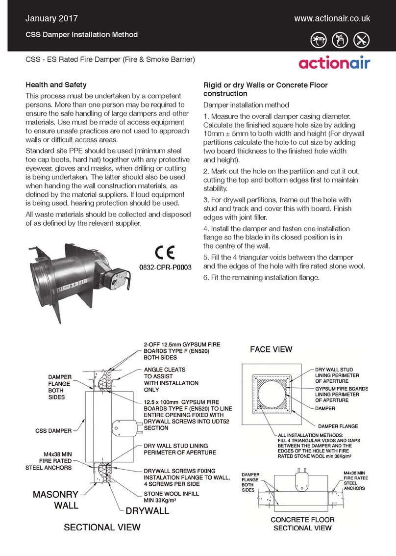
Dry Wall Fix Cleats (DWFX-C) Installation Methods
SmokeShield PTC - ES Rated Fire Damper (Fire & Smoke Barrier)
FireShield PTC - E Rated Fire Damper (Fire Barrier)
www.actionair.co.ukJanuary 2017
Health and Safety
This process must be undertaken by a competent
persons. More than one person may be required to
ensure the safe handling of large dampers and other
materials. Use must be made of access equipment
to ensure unsafe practices are not used to approach
walls or dicult access areas.
Standard site PPE should be used (minimum steel
toe cap boots, hard hat) together with any protective
eyewear, gloves and masks, when drilling or cutting
is being undertaken. The latter should also be used
when handing the wall construction materials, as
dened by the material suppliers. If loud equipment
is being used, hearing protection should be used.
All waste materials should be collected and
disposed of as dened by the relevant supplier.
Vertical in Dry wall - DWFX-C
Damper Installation Method
1. Fit track (of partition) to the ceiling.
2. Suspend the damper from the ceiling through
the centre of the partition ceiling track using 10mm
studding drop rods.
3. Frame out the damper using tracks and studs lined
with board. This is done with a lined track above the
damper crossing between the nearest two full height
studs, two vertical lined studs as close to the damper
as possible (outside the cleats) from the top cross
track to the oor and a lined cross track below the
damper between the two vertical studs.
4. Build the partition to the track and stud framework,
coming as close to the damper as possible.
5. Insulate the wall with mineral/stone wool
6. Seal the damper to the partition with intumescent
sealant and add patresses to both sides down to the
damper spigot. Seal these to the damper spigot with
intumescent sealant.
7. Finish the wall as standard practice
Commissioning
The procedure detailed under periodic maintenance
should be followed
Periodic maintenance
As detailed in BS 9999:2008
1. For dampers this is at least once per year for
units with spring operation.
2. Units operating in dust laden atmospheres,
should be checked more often to suit the severity
of the conditions
3. Units associated with systems may be required
to be checked, as part of the system, as often
as once per week or month to ensure ongoing
condence in the life safety system. This may
be seen as analogous to re alarm systems.
Procedure
1. The units should be carefully inspected and
cleaned of dust and debris
2. The units should then be lubricated with a light
oil, by wiping this over all the surfaces
3. The mode should be operated to ensure that it
is moving the blades from open to closed and the
reverse.
4. If the end switches (in the mode) are being used,
it should be checked that they are actually indicating
that the blades are open or closed. This is done
by running a cycle and checking both the blades
(open and closed) and the indication that the
micro switches are feeding back to.
Actuator tting (If required)
The control mode/actuator should be tted in
accordance with the documentation supplied with it.
Assessed to ISO 9001:2008
LPCB Cert No. 17
LPS1162 Cert No. 017a
Inspection and handover check sheet Damper Installation Certicate
This certicate applies only to Actionair products. The installer
must complete this installation certicate when installing re and smoke dampers.
A separate certicate must be completed for each individual re and smoke damper.
No. Question Action Tick
1 Are the dampers the correct type? Conrm damper is correct type i.e. SmokeShield ¨
2 Are the dampers located correctly? The damper location is to be checked against the
installation drawings/details ¨
3Are the dampers correctly identied? Unique system ID to be clearly indicated on the damper
or other agreed location. ¨
4 Have supports for both the damper and the adjacent ductwork
been installed in accordance with the approved manner? ¨
5Are the dampers tted in the correct orientation? Conrm the damper is installed the correct way up and
relative to airow and/or access. ¨
6Is access through the ductwork, to the damper unobstructed? Unobstructed space should be provided for safe access
to the damper. This must include access through ceiling
voids and adjacent services. Damper installer to advise
the system designer if problems are foreseen.
¨
7 Has the space around the damper and within the opening been
left clear and not been used for other services?
Other services within the installation opening will
invalidate the installation method. Damper installer to
advise the lead contractor if problems are foreseen.
¨
8 Using the access opening provided, are the damper blades in
the open position?
Check position of damper blades. ¨
9 Has the damper been checked for internal cleanliness, free
from damage and that vertical casings in particular are free
from debris?
With the damper in the closed position, inspect for
damage. ¨
10 Has the damper been released to simulate operation of the
thermal release? (Damper drop test)
Ensure damper operation is free from interference. ¨
11 Have the damper blades been re-set following drop test and
the access panel replaced?
After re-setting the damper, check the position shown
on the blade position indicator is correct. ¨
12 At the time of damper handover, is the re barrier and
penetration seal complete?
Damper installer to record on the handover register if
any following trades are still to complete their activities. ¨
13 Is the damper installation complete and available for handover
prior to system commissioning?
Obtain the relevant acceptance of the damper installation
from the CDM coordinator. ¨
14 Is the completed handover register cross-referenced back to
the identication codes listed in the system designers damper
schedule?
¨
Damper Unique System I.D:
Name of installation location:
Address:
Installation location identication section/oor/room:
Damper product type:
Release fuse temperature:
Notes/Considerations:
Installed by:
Company Name:
Address:
Company Telephone No:
Installers Name:
Installers Telephone No:
Date of installation:
It is hereby veried that the damper detailed above has been installed and tested according
to the manufactures recommendations:
Installers signature: Date:
South Street, Whitstable,
Kent, CT5 3DU
Tel: +44 (0)1227 276100
Fax: +44 (0)1227 264262
Email: sales@actionair.co.uk
Website: www.actionair.co.uk
LNNN00353 (3.1)

This manual suits for next models

3

Other actionair Fire And Smoke Damper manuals

actionair CSS User manual

actionair

actionair CSS User manual

actionair SmokeShield PTC Assembly instructions

actionair

actionair SmokeShield PTC Assembly instructions

actionair DWFX-F User manual

actionair

actionair DWFX-F User manual

actionair Smoke/Shield PTC User manual

actionair

actionair Smoke/Shield PTC User manual

actionair FG Series User manual

actionair

actionair FG Series User manual

actionair A60 Configuration guide

actionair

actionair A60 Configuration guide

Popular Fire And Smoke Damper manuals by other brands

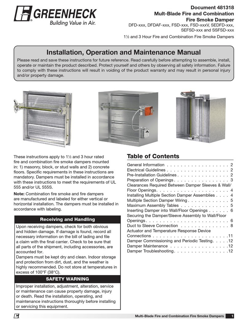
Greenheck ES Series Installation, operation and maintenance manual

Greenheck

Greenheck ES Series Installation, operation and maintenance manual

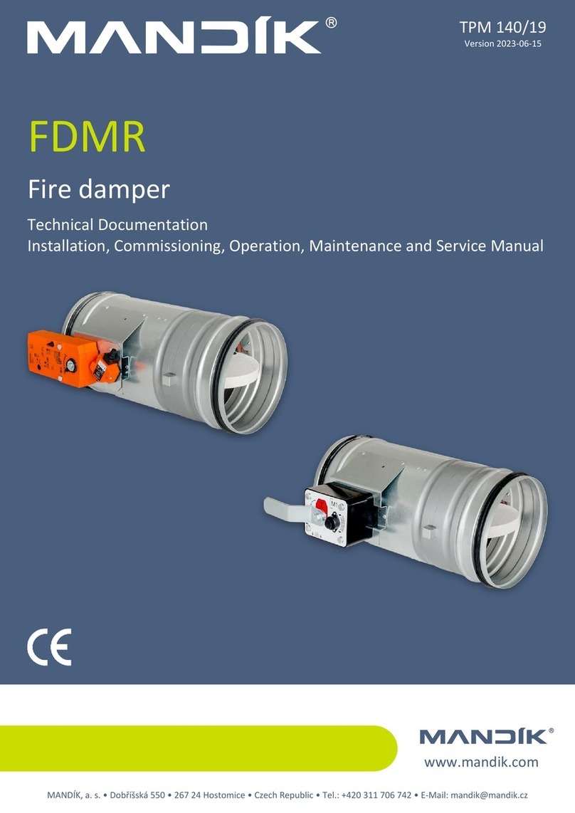
Mandik FDMR Technical documentation

Mandik

Mandik FDMR Technical documentation

Rf-t CU2 manual

Rf-t

Rf-t CU2 manual

klimaoprema FDC Series product manual

klimaoprema

klimaoprema FDC Series product manual

mercor mcr S-THERM C Operation and maintenance manual

mercor

mercor mcr S-THERM C Operation and maintenance manual

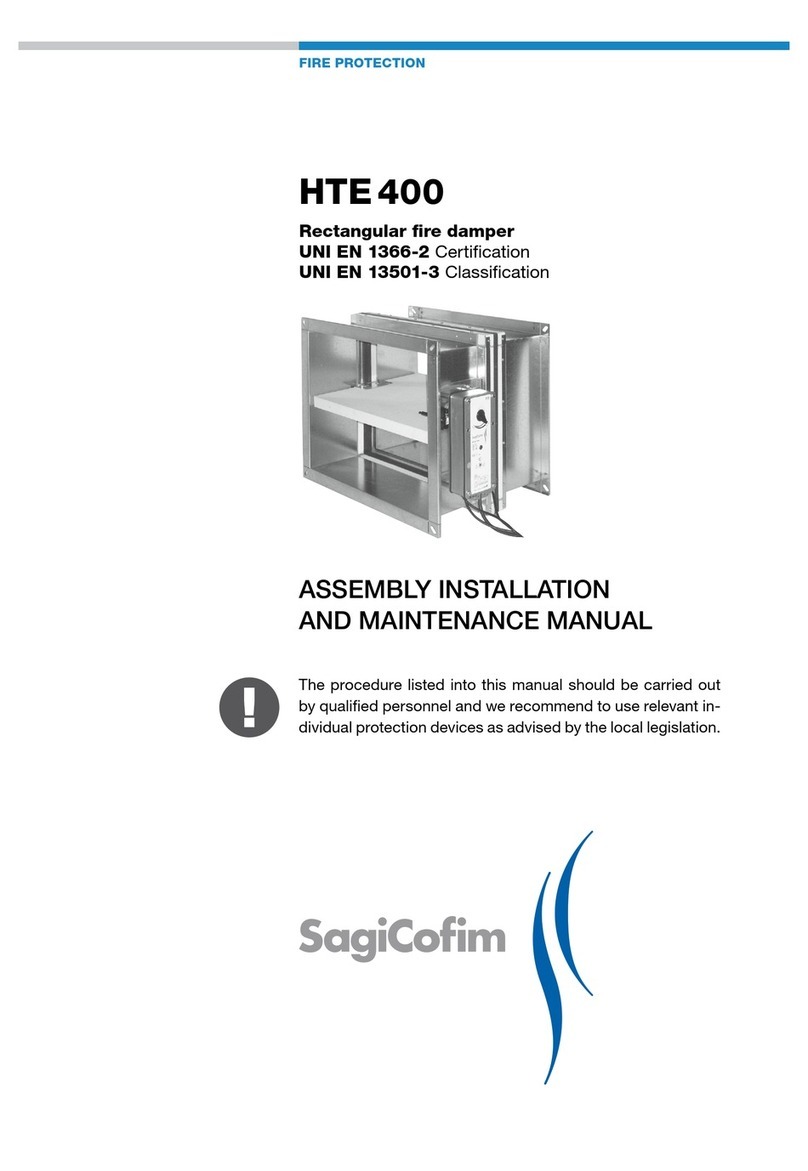
SagiCofim HTE 400 Assembly, installation and maintenance manual

SagiCofim

SagiCofim HTE 400 Assembly, installation and maintenance manual

Greenheck DFD Series manual

Greenheck

Greenheck DFD Series manual

Madel FMC-EIS-120 manual

Madel

Madel FMC-EIS-120 manual

klimaoprema FDC25 Series installation manual

klimaoprema

klimaoprema FDC25 Series installation manual

Ace FYN-S1 Operating and mounting instructions

Ace

Ace FYN-S1 Operating and mounting instructions

Schako BSK-RPR Technical documentation

Schako

Schako BSK-RPR Technical documentation

SMAY KWP-P-E Technical documentation

SMAY

SMAY KWP-P-E Technical documentation

GILBERTS SMOKEGARD manual

GILBERTS

GILBERTS SMOKEGARD manual

mercor mcr WIP Series Operation and maintenance manual

mercor

mercor mcr WIP Series Operation and maintenance manual

VENCO ES Series Installation, operation and maintenance manual

VENCO

VENCO ES Series Installation, operation and maintenance manual

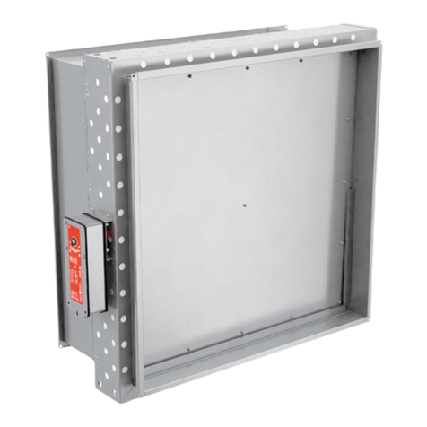
Swegon actionair FireShield manual

Swegon

Swegon actionair FireShield manual

Bevent Rasch FENIX4 Commissioning Instruction

Bevent Rasch

Bevent Rasch FENIX4 Commissioning Instruction

Greenheck CRD-300WT Installation, operation and maintenance manual

Greenheck

Greenheck CRD-300WT Installation, operation and maintenance manual

manuals.online logo
manuals.online logoBrands
  • About & Mission
  • Contact us
  • Privacy Policy
  • Terms and Conditions

Copyright 2025 Manuals.Online. All Rights Reserved.