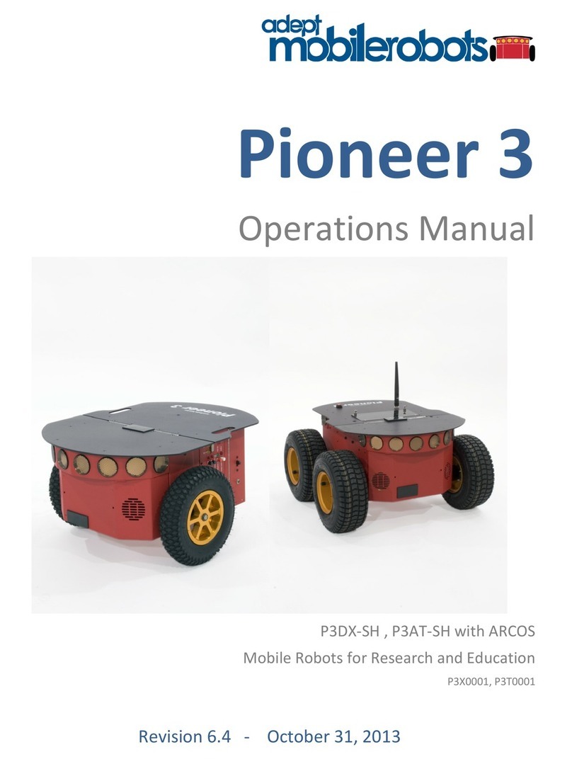
ActivMedia Robotics Pioneer 3 User manual

Pioneer 3™
Operations Manual
with
NEW Renesas SH2-based Controller
&
A
ctivMedia’s Robot Control & O
p
erations Software

Copyright © 2004, ActivMedia Robotics, LLC. All rights reserved.
Under international copyright laws, this manual or any portion of it may not be copied or
in any way duplicated without the expressed written consent of ActivMedia Robotics.
The software on disk, CD-ROM, and/or in the controller’s FLASH, which accompany the
robot and are available for network download by ActivMedia Robotics customers, are
solely owned and copyrighted or licensed by ActivMedia Robotics, LLC.
Developers and users are authorized by revocable license to develop and operate
custom software for personal research and educational use only. Duplication,
distribution, reverse-engineering, or commercial application of the ActivMedia Robotics
software and hardware without the expressed written consent of ActivMedia Robotics,
LLC, is explicitly forbidden.
The various names and logos for products used in this manual are often registered
trademarks or trademarks of their respective companies. Mention of any third-party
hardware or software constitutes neither an endorsement nor a recommendation.
Pioneer 3-SH Operations Manual, version 1, September 2004
ii

ActivMedia Robotics
Important Safety Instructions
Read the installation and operations instructions before using the equipment.
Avoid using power extension cords.
To prevent fire or shock hazard, do not expose the equipment to rain or moisture.
Refrain from opening the unit or any of its accessories.
Keep wheels away from long hair or fur.
Never access the interior of the robot with charger attached or batteries inserted.
Inappropriate Operation
Inappropriate operation voids your warranty! Inappropriate operation includes, but is
not limited to:
Dropping the robot, running it off a ledge, or otherwise operating it in an
irresponsible manner
Overloading the robot above its payload capacity
Getting the robot wet
Continuing to run the robot after hair, yarn, string, or any other items have become
wound around the robot’s axles or wheels
Opening the robot with charger attached and/or batteries inserted
All other forms of inappropriate operation or care
Use ActivMedia Robotics’ authorized parts ONLY;
warranty void otherwise.
iii

Table of Contents
CHAPTER 1 INTRODUCTION................................................................................................................. 1
ROBOT PACKAGES....................................................................................................................................... 1
Basic Components (all shipments).......................................................................................................... 1
Optional Components and Attachments (partial list) ............................................................................. 1
User-Supplied Components / System Requirements ............................................................................... 2
ADDITIONAL RESOURCES ............................................................................................................................ 2
Support Website...................................................................................................................................... 2
Newsgroups ............................................................................................................................................ 2
Support ................................................................................................................................................... 3
CHAPTER 2 WHAT IS PIONEER? .......................................................................................................... 4
PIONEER REFERENCE PLATFORM ................................................................................................................ 4
PIONEER FAMILY OF ROBOT CONTROLLERS AND OPERATION SYSTEM SOFTWARE..................................... 4
PORTS AND POWER...................................................................................................................................... 5
CLIENT SOFTWARE...................................................................................................................................... 5
ARIA ....................................................................................................................................................... 6
Mapping, Navigation, and Localization ................................................................................................. 6
MODES OF OPERATION ................................................................................................................................6
Server Mode............................................................................................................................................ 6
Maintenance and Standalone Modes...................................................................................................... 7
Joydrive Mode ........................................................................................................................................ 7
THE PIONEER LEGACY................................................................................................................................. 7
Pioneer AT.............................................................................................................................................. 8
Pioneer 2™ and PeopleBot™ ................................................................................................................ 8
Pioneer 3™ and Recent Pioneer 2-DX8™, -AT8™, and Plus™ Mobile Robots................................... 8
Pioneer 3™ SH Robots........................................................................................................................... 9
CHAPTER 3 SPECIFICATIONS & CONTROLS ................................................................................. 10
PHYSICAL CHARACTERISTICS AND COMPONENTS ..................................................................................... 10
DECK......................................................................................................................................................... 11
MOTOR STOP BUTTON............................................................................................................................... 11
USER CONTROL PANEL ............................................................................................................................. 12
Power and Status Indicators................................................................................................................. 12
Buzzer ................................................................................................................................................... 12
Serial Port ............................................................................................................................................ 12
Power Switches..................................................................................................................................... 13
Reset and Motors .................................................................................................................................. 13
BODY, NOSE, AND ACCESSORY PANELS ................................................................................................... 13
Nose ...................................................................................................................................................... 13
Access Panels ....................................................................................................................................... 14
SONAR....................................................................................................................................................... 14
Multiplexed Operation.......................................................................................................................... 14
Sensitivity Adjustment........................................................................................................................... 14
MOTORS, WHEELS, AND POSITION ENCODERS .......................................................................................... 15
BATTERIES AND POWER ............................................................................................................................ 15
Battery Indicators and Low Voltage Conditions...................................................................................16
Recharging ........................................................................................................................................... 16
SAFETY ARCOS WATCHDOGS ................................................................................................................. 16
CHAPTER 4 ACCESSORIES................................................................................................................... 17
JOYSTICK AND JOYDRIVE MODE ............................................................................................................... 17
BUMPERS................................................................................................................................................... 17
DOCKING-CHARGING ACCESSORY ............................................................................................................ 18
Manual Operation (Robot Power OFF) ............................................................................................... 18
Manual Operation (Robot Power and Systems ON)............................................................................. 18
RADIO CONTROLS AND ACCESSORIES ....................................................................................................... 19
INTEGRATED PC ........................................................................................................................................ 20
Computer Control Panel....................................................................................................................... 20
iv

ActivMedia Robotics
Operating the Onboard PC ...................................................................................................................21
PC Networking ......................................................................................................................................21
UPS and Genpowerd.............................................................................................................................22
CHAPTER 5 QUICK START....................................................................................................................24
PREPARATIVE ASSEMBLY ..........................................................................................................................24
Install ARIA ...........................................................................................................................................24
Install Batteries .....................................................................................................................................25
Client-Server Communications .............................................................................................................25
STARTING UP CLIENT AND SERVER ...........................................................................................................25
Demo Startup Options ...........................................................................................................................25
A Successful Connection .......................................................................................................................26
OPERATING THE ARIA DEMONSTRATION CLIENT .....................................................................................26
DISCONNECTING ........................................................................................................................................27
QUICKSTART TROUBLESHOOTING ..............................................................................................................27
Proper Connections...............................................................................................................................27
CHAPTER 6 ARCOS .................................................................................................................................29
CLIENT-SERVER COMMUNICATION PACKET PROTOCOLS...........................................................................29
Packet Checksum...................................................................................................................................30
Packet Errors ........................................................................................................................................30
THE CLIENT-SERVER CONNECTION............................................................................................................31
Autoconfiguration (SYNC2)...................................................................................................................31
Opening the Servers—OPEN ................................................................................................................31
Keeping the Beat—PULSE....................................................................................................................32
Closing the Connection—CLOSE..........................................................................................................32
SERVER INFORMATION PACKETS ...............................................................................................................32
CLIENT COMMANDS ...................................................................................................................................32
MOTION COMMANDS .................................................................................................................................33
ActivMedia Robots in Motion................................................................................................................36
PID Controls .........................................................................................................................................37
Position Integration...............................................................................................................................37
DriftFactor, RevCount, and TicksMM...................................................................................................38
SONAR .......................................................................................................................................................38
Enable/Disabling Sonar ........................................................................................................................39
Polling Sequence ...................................................................................................................................39
Polling Rate...........................................................................................................................................39
STALLS AND EMERGENCIES ........................................................................................................................39
ACCESSORY COMMANDS AND PACKETS ....................................................................................................40
Packet Processing .................................................................................................................................40
CONFIGpac and CONFIG Command ..................................................................................................40
SERIAL .......................................................................................................................................................42
HOST-to-AUX Serial Transfers.............................................................................................................42
ENCODERS .................................................................................................................................................42
BUZZER SOUNDS........................................................................................................................................42
TCM2 ........................................................................................................................................................43
ONBOARD PC.............................................................................................................................................43
INPUT OUTPUT (I/O) ..................................................................................................................................44
Gripper..................................................................................................................................................44
Heading Correction Gyro......................................................................................................................45
User I/O.................................................................................................................................................45
Bumper and IR I/O ................................................................................................................................46
IO packets..............................................................................................................................................46
DOCKING/CHARGING SYSTEM ...................................................................................................................46
Digital Port Controls.............................................................................................................................47
Docking/Charging Servers ....................................................................................................................47
Monitoring the Recharge Cycle.............................................................................................................48
CHAPTER 7 UPDATING & RECONFIGURING ARCOS ...................................................................49
WHERE TO GET ARCOS SOFTWARE..........................................................................................................49
ARCOS MAINTENANCE MODE..................................................................................................................49
v

Enabling Maintenance Mode on the Controller ................................................................................... 49
ARCOSCF................................................................................................................................................. 50
STARTING ARCOSCF ................................................................................................................................50
CONFIGURING ARCOS PARAMETERS ....................................................................................................... 51
Interactive Commands.......................................................................................................................... 51
Changing Parameters........................................................................................................................... 51
SAVE YOUR WORK.................................................................................................................................... 52
PID PARAMETERS ..................................................................................................................................... 54
DRIFTFACTOR, TICKSMM, AND REVCOUNT .............................................................................................. 54
STALLVAL AND STALLCOUNT .................................................................................................................. 55
BUMPERS................................................................................................................................................... 55
CHAPTER 8 CALIBRATION & MAINTENANCE .............................................................................. 56
TIRE INFLATION ........................................................................................................................................ 56
CALIBRATING YOUR ROBOT ..................................................................................................................... 56
DRIVE LUBRICATION ................................................................................................................................. 57
BATTERIES ................................................................................................................................................ 57
Changing Batteries ............................................................................................................................... 57
Hot-Swapping the Batteries.................................................................................................................. 57
Charging the Batteries.......................................................................................................................... 57
Automated Docking/Charging System .................................................................................................. 58
Alternative Battery Chargers................................................................................................................ 58
TIGHTENING THE AT DRIVE BELT............................................................................................................. 58
GETTING INSIDE ........................................................................................................................................ 59
Removing the Nose ............................................................................................................................... 59
Opening the Deck ................................................................................................................................. 60
FACTORY REPAIRS .................................................................................................................................... 60
APPENDIX A.............................................................................................................................................. 61
CONTROLLER PORTS & CONNECTIONS...................................................................................................... 61
SH2 CONTROLLER .................................................................................................................................... 61
Power Connector.................................................................................................................................. 61
Serial Ports........................................................................................................................................... 62
User I/O, Gripper, Docking/Charging Interface .................................................................................. 62
Motors, Encoders, and IR Sensors........................................................................................................ 63
Joystick Port ......................................................................................................................................... 63
Bumper Ports........................................................................................................................................ 63
User Control Board Interface............................................................................................................... 64
Sonar Connectors ................................................................................................................................. 64
Heading Correction Gyro..................................................................................................................... 64
Tilt/Roll Sensor ..................................................................................................................................... 64
I2C Interface ......................................................................................................................................... 65
APPENDIX B.............................................................................................................................................. 66
MOTOR-POWER BOARD ............................................................................................................................ 66
Configuration for Current and Temperature Sensing........................................................................... 66
Controller Power and Interface............................................................................................................ 67
Radio, Auxiliary, and User Power Connectors .................................................................................... 67
IR Signal and Power............................................................................................................................. 68
APPENDIX C.............................................................................................................................................. 69
ETHERNET-TO-SERIAL DEVICE SETTINGS ................................................................................................. 69
LAN IP SETTINGS ..................................................................................................................................... 69
Console mode: ...................................................................................................................................... 70
Webpage ............................................................................................................................................... 70
Peer-to-Peer Networking...................................................................................................................... 70
APPENDIX D.............................................................................................................................................. 71
SPECIFICATIONS ........................................................................................................................................ 71
WARRANTY & LIABILITIES ................................................................................................................ 73
vi

ActivMedia Robotics
Introduction
Figure 1. Pioneer Mobile Robots first
appeared commercially in 1995.
Chapter 1
Congratulations on your purchase and
welcome to the rapidly growing community
of developers and enthusiasts of ActivMedia
Robotics’ intelligent mobile robots.
This Pioneer 3-SH Operations Manual provides
both the general and technical details you
need to operate your new Pioneer 3-DX or
–AT robot and to begin developing your own robotics hardware and software.
For operation of previous versions of Pioneer 2 and 3 which use the Siemens C166- or
Hitachi H8S-based robot controllers, original motor-power boards, and support systems,
activmedia.com for their related documentation.
ROBOT PACKAGES
Our experienced manufacturing staff put your mobile robot and accessories through a
“burn in” period and carefully tested them before shipping the products to you. In
addition to the companion resources listed above, we warrant your ActivMedia robot
and our manufactured accessories against mechanical, electronic, and labor defects
for one year. Third-party accessories are warranted by their manufacturers, typically for
90 days.
Even though we’ve made every effort to make your ActivMedia Robotics package
complete, please check the components carefully after you unpack them from the
shipping crate.
Basic Components (all shipments)
One fully assembled mobile robot with battery
CD-ROM containing licensed copies of ActivMedia software and documentation
Hex wrenches and assorted replacement screws
Replacement fuse(s)
Set of manuals
Registration and Account Sheet
Optional Components and Attachments (partial list)
Battery charger (some contain power receptacle and 220VAC adapters)
Automated dock and recharge station
Onboard PC computer and accessories
Radio Ethernet
Supplementary and replacement batteries
3-Battery Charge Station (110/220 VAC)
Added sonar arrays
2-DOF Gripper
5-DOF P2 Arm with gripper
ActivMedia Color Tracking System (ACTS)
Stereo Vision Systems
Pan-Tilt-Zoom Surveillance Cameras
Custom Vision System
Range-finding laser
Global Positioning System
1

Congratulations
Heading-correction gyro
Compass
Bumper rings
Serial cables for external connections
Many more…
User-Supplied Components / System Requirements
Client PC: 586-class or later PC with Microsoft Windows© or Linux OS
One RS-232 compatible serial port or Ethernet
Four megabytes of available hard-disk storage
ADDITIONAL RESOURCES
New ActivMedia Robotics customers get three additional and valuable resources:
A private account on our support Internet website for downloading software,
updates, and manuals
Access to private newsgroups
Direct access to the ActivMedia Robotics technical support team
Support Website
We maintain a 24-hour, seven-day per week World Wide Web server where customers
may obtain software and support materials:
http://robots.activmedia.com
Some areas of the website are restricted to licensed customers. To gain access, enter
the username and password written on the Registration & Account Sheet that
accompanied your robot.
Newsgroups
We maintain several email-based newsgroups through which ActivMedia robot owners
share ideas, software, and questions about the robot. Visit the support
http://robots.activmedia.com website for more details. To sign up for pioneer-users,
for example, send an e-mail message to the –requests automated newsgroup server:
From: <your return e-mail address goes here>
Subject: <choose one command:>
help (returns instructions)
lists (returns list of newsgroups)
subscribe
unsubscribe
Our SmartList-based listserver will respond automatically. After you subscribe, send your
email comments, suggestions, and questions intended for the worldwide community of
Pioneer users:1
From: <your return e-mail address goes here>
Subject: <something of interest to pioneer users>
Access to the pioneer-users newslist is limited to subscribers, so your address is safe
from spam. However, the list currently is unmoderated, so please confine your
1Note: Leave out the –requests part of the email address when sending messages to the newsgroup.
2

ActivMedia Robotics
comments and inquiries to issues concerning the operation and programming of Pioneer
or PeopleBot robots.
Support
Have a problem? Can’t find the answer in this or any of the accompanying manuals? Or
do you know a way that we might improve our robots? Share your thoughts and
questions with us from the online form at the support website:
http://robots.activmedia.com/techsupport
or by email:
Please include your robot's serial number (look for it beside the Main Power switch)we
often need to understand your robot's configuration to best answer your question.
Tell us your robot’s SERIAL NUMBER.
Your message goes directly to the ActivMedia Robotics technical support team. There a
staff member will help you or point you to a place where you can find help.
Because this is a support option, not a general-interest newsgroup like pioneer-users,
we reserve the option to reply only to questions about problems with your robot or
software.
See Chapter 8, Maintenance & Repair, for more details.
Use ActivMedia Robotics’ authorized parts ONLY;
warranty void otherwise.
3

What is Pioneer?
Figure 2. Some ActivMedia robots
Chapter 2
What Is Pioneer?
Pioneer is a family of mobile robots, both
two-wheel and four-wheel drive, including
the Pioneer 1 and Pioneer AT, Pioneer 2™ -
DX, -DXe, -DXf, -CE, -AT, the Pioneer 2™-
DX8/Dx8 Plus and -AT8/AT8 Plus, and the
newest Pioneer 3-DX and -AT mobile robots.
These small, research and development
platforms share a common architecture and
foundation software with all other
ActivMedia robots including AmigoBot™,
PeopleBot™ V1, Performance PeopleBot™,
and PowerBot™ mobile robots.
PIONEER REFERENCE PLATFORM
ActivMedia robots set the standards for intelligent mobile platforms by containing all of
the basic components for sensing and navigation in a real-world environment. They
have become reference platforms in a wide variety of research projects, including
several US Defense Advanced Research Projects Agency (DARPA) funded studies.
Every ActivMedia robot comes complete with a sturdy aluminum body, balanced drive
system (two-wheel differential with caster or four-wheel skid-steer), reversible DC motors,
motor-control and drive electronics, high-resolution motion encoders, and long-life, hot-
swappable battery power, all managed by an onboard controller and mobile-robot
server software.
Besides the open-systems robot-control server software onboard the robot controller,
every ActivMedia robot also comes with a host of advanced robot-control client
software applications and applications-development environments. Software
development includes our own foundation ActivMedia Robotics Interface for
Applications (ARIA), released under the GNU Public License, and complete with fully
documented C++, Java, and Python libraries and source code. Several third-party
robotics applications development environments also have emerged from the research
community for ActivMedia robots, including Saphira from SRI International, Ayllu from
Brandeis University, Pyro from Bryn Mawr and Swarthmore Colleges, Player/Stage from
the University of Southern California, and Carmen from Carnegie-Mellon University.
Every ActivMedia robot comes with a plethora of expansion options, including built-in
hardware support for sonar and bump sensors and lift/gripper effectors, as well as serial
port and server software support for a number of sensors, effectors, and control
accessories, like an onboard PC system, automated docking/recharging system, laser
range-finder, 5-DOF arm, robotic pan-tilt cameras, and much, much more.
PIONEER FAMILY OF ROBOT CONTROLLERS AND OPERATION SYSTEM SOFTWARE
The original Pioneer 1 mobile robot contained a controller based on the Motorola
68HC11 microprocessor and powered by Pioneer Server Operating System (PSOS)
software. The first generation of Pioneer 2 and PeopleBot robots used a Siemens C166-
based controller with Pioneer 2 Operating System (P2OS) software. Until now, the Pioneer
3, Performance PeopleBot, and PowerBot robots had an Hitachi H8S-based controller
with ActivMedia Robotics Operating System (AROS) software.2
4
2AmigoBot has an H8S-based controller, too, but uses the AmigoBot Operating System tailored for its
electronics.

ActivMedia Robotics
All ActivMedia robots now use a revolutionary new, high-performance controller with
ActivMedia’s Robot Control and Operations Software (ARCOS) based on the new-
generation 32-bit Renesas SH2 microprocessor. This new P3-SH controller with completely
renovated and improved code provides unprecedented performance and flexibility in
robotics control. But you might not even notice. Because we have taken great care to
ensure backward compatibility across ActivMedia’s entire history of robots, client
software written to operate an ancient P2OS-based Pioneer AT will work with a brand
new P3-AT with little or no modification. Client-server communication over a serial
communication link remain identical as do support for all robotics commands. See
Chapter 6, ActivMedia’s Robot Control Operations Software, for details.
PORTS AND POWER
Your ActivMedia robot has a variety of expansion power and I/O ports for attachment
and close integration of a client PC, sensors, and a variety of accessories—all accessible
through a common application interface to the robot’s server software, ARCOS.
Features include:
44.2368 MHz Renesas SH2 32-bit RISC microprocessor with 32K RAM and 128K FLASH
4 RS-232 serial ports (5 connectors) configurable from 9.6 to 115.2 kilobaud
4 Sonar arrays of up to 8 sonar each
2 8-bit bumpers/digital input connectors
Gripper/User I/O port with 8-bits digital I/O, analog input, and 5/12 VDC power
Heading correction gyro port
Tilt/roll sensor port
2-axis, 2-button joystick port
User Control Panel
Controller HOST serial connector
Main power and bi-color LED battery level indicators
2 AUX power switches (5 and 12 VDC) with related LED indicators
RESET and MOTORS pushbutton controls
Piezo buzzer
Motor/Power Board (drive system) interface with PWM and motor-direction control
lines and 8-bits of digital input
I2C interface with 4-line X 20-character LCD support
With the onboard PC option, your ActivMedia robot becomes an autonomous agent.
With Ethernet-ready onboard autonomy, your robot even becomes an agent for multi-
intelligence work.
Figure 3. ActivMedia’s robot servers require a PC to run client software for
intelligent robotics command and control operations.
CLIENT SOFTWARE
All ActivMedia robots operate as the server in a client-server environment: Their
controllers handle the low-level details of mobile robotics, including maintaining the
platform’s drive speed and heading over uneven terrain, acquiring sensor readings, such
5

What is Pioneer?
as from the sonar, and managing attached accessories like the Gripper. To complete
the client-server architecture, ActivMedia robots require a PC connection: software
running on a computer connected with the robot’s controller via the HOST serial link and
which provides the high-level, intelligent robot controls, including obstacle avoidance,
path planning, features recognition, localization, navigation, and so on.
An important benefit of ActivMedia Robotics’ client-server architecture is that different
robot servers can be run using the same high-level client. Several clients also may share
responsibility for controlling a single mobile server, which permits experimentation in
distributed communication, planning, and control.
ARIA
Figure 4. ARIA's architecture
The ActivMedia Robotics Interface for
Applications (ARIA) software comes with every
ActivMedia robot. It is a C++-based open-
source development environment that
provides a robust client-side interface to a
variety of intelligent robotics systems, including
your ActivMedia robot’s controller and
accessory systems.
ARIA is the ideal platform for integration of your
own robot-control software, since it neatly
handles the lowest-level details of client-server
interactions, including serial communications,
command and server-information packet processing, cycle timing, and multithreading,
as well as a variety of accessory controls, such as for a scanning laser-range finder,
motion gyros, among many others.
What’s more, ARIA comes complete with source code so that you may examine the
software and modify it for your own sensors and applications.
Mapping, Navigation, and Localization
ActivMedia Robotics’ also has a comprehensive suite of client tools and applications by
which, with a laser range-finder enabled ActivMedia robot, you automatically create,
edit, and use maps and floorplans for advanced robotics applications, including
localization and navigation. For much more information about ARNL, MobileEyes™, and
our many commercial ventures, visit http://www.mobilerobots.com and contact
MODES OF OPERATION
You may operate your Pioneer 3 robot in one of four modes:
Server
Joydrive
Maintenance
Standalone
Server Mode
The new Renesas SH2 microprocessor-based controller comes with 128K of
reprogrammable FLASH and 32K dynamic RAM memory. We don't recommend that you
start learning SH2 programming. Rather, the robot comes to you installed with the latest
ARCOS servers.
6

ActivMedia Robotics
In conjunction with client software like ARIA running on an onboard or other user-supplied
computer, ARCOS lets you take advantage of modern client-server and robot-control
technologies to perform advanced robot tasks. Most users run their ActivMedia robot in
server mode, because it gives them quick, easy access to its robotics functionality while
working with high-level software on a familiar host computer.
Maintenance and Standalone Modes
For experiments in controller-level operation of your robot’s functions, you may
reprogram the onboard FLASH for direct and standalone operation of your ActivMedia
robot. We supply the means to download and debug (ARSHstub embedded GDB
interface), but not the controller's programming software, for you to work in standalone
mode.
The utilities we provide for you to reprogram the SH2-based controller's FLASH also may
be used to update and upgrade your robot’s ARCOS. In a special Maintenance Mode,
you also adjust your robot’s operating parameters that ARCOS uses as default values on
startup or reset. See Chapter 7, Updating & Reconfiguring ARCOS, for much more detail.
We typically provide the maintenance utilities and ARCOS upgrades free for download
from our website, so be sure to sign up for the pioneer-users email newslist. That's
where we notify our customers of the upgrades, as well as where we provide access to
ActivMedia robot users worldwide.
Joydrive Mode
Finally, we provide onboard software and controller hardware that let you drive the
robot from a tethered joystick when not otherwise connected with a controlling client.
See Chapter 4 for more details.
Figure 5. The original Pioneer 1 and Pioneer AT
THE PIONEER LEGACY
Commercially introduced in
the summer of 1995, Pioneer
1 was the original platform.
Intended mostly for indoor
use on hard, flat surfaces,
the robot had solid rubber
tires and a two-wheel
differential, reversible drive
system with a rear caster for
balance. It came with a single-board 68HC11-based robot controller and the Pioneer
Server Operating System (PSOS) software. The Pioneer 1 also came standard with seven
sonar range finders (two side-facing and five forward-facing) and integrated wheel
encoders. Its low-cost and high-performance caused an explosion in the number of
researchers and developers who now have access to a real, intelligent mobile robotic
platform.
Software-wise, the Pioneer 1 initially served as a platform for SRI International's AI/fuzzy
logic-based Saphira robotics applications development. But it wasn't long before
Pioneer’s open architecture became the popular platform for the development of a
variety of alternative robotics software environments.
7

What is Pioneer?
Pioneer AT
Functionally and programmatically identical to the Pioneer 1, the four-wheel drive, skid-
steer Pioneer AT was introduced in the summer of 1997 for operation in uneven indoor
and outdoor environments, including loose, rough terrain.
Except for the drive system, there were no operational differences between the Pioneer
AT and the Pioneer 1: The integrated sonar arrays and controllers were the same; they
shared accessories; and applications developed for the Pioneer 1 worked with little or no
porting on the AT.
Pioneer 2™ and PeopleBot™
The next generation of Pioneer, including the
Pioneer 2-DX, -CE, and -AT, introduced in fall of
1998 through summer of 1999, improved upon
the Pioneer 1 legacy while retaining its many
important advantages.3Indeed, in most
respects, particularly with applications software,
Pioneer 2 worked identically to Pioneer 1 models,
but offered many more expansion options,
including a client PC onboard the robot.
Figure 6. The Performance
PeopleBot sports an attractive body
design and bundled systems,
including voice synthesis and
recognition for human-interaction
research and applications.
The ActivMedia Robotics Pioneer 2 models -DX, -
DE, -DXe, -DXf, and -AT, and the V1 and
Performance PeopleBot robots used a 20 MHz
Siemens 88C166-based controller, with
independent motor-power and sonar controller
boards for a versatile operating environment.
Sporting a more holonomic body, larger wheels
and stronger motors for better indoor
performance, Pioneer 2-DX, -DXe, -DXf, and -CE
models, like Pioneer 1, were two-wheel,
differential-drive mobile robots.
The four-wheel drive Pioneer 2-AT had four
independent motors and drivers. Unlike its
Pioneer AT predecessor, the Pioneer 2-AT came
with a stall-detection system and inflatable
pneumatic tires with metal wheels for much
more robust operation in rough terrain, as well as
the ability to carry nearly 30 kilograms (66 lbs) of
payload and climb a 60-percent grade.
Other Pioneer 2-like robots include the Performance PeopleBot robots, which were
introduced in 2000. They are architecturally Pioneer 2 robots, but with stronger motors
and integrated human-interaction features, including a pedestal extension, integrated
voice and sound synthesis and recognition—ideal for human-interaction studies as well
as for commercial and consumer mobile-robotics applications.
Pioneer 3™ and Recent Pioneer 2-DX8™, -AT8™, and Plus™ Mobile Robots
Two new models of Pioneer 2 appeared in the summer of 2002, two more at the
beginning of 2003, and the Pioneer 3 debuted in the summer of 2003. All used a
controller based on the Hitachi H8S microprocessor, with new control systems software
8
3Price/performance ratio included! The much more capable and expandable Pioneer 2 was introduced four
years later for just a few hundred dollars (US) more than the original Pioneer 1.

ActivMedia Robotics
(AROS) and I/O expansion capabilities. The Pioneer 3 and 2-Plus robots also had new,
more powerful motor/power systems for better navigational control and payload.4
Pioneer 3™ SH Robots
Hardware-wise, the latest Pioneer, PeopleBot™, and PowerBot™ robots—all introduced
in summer of 2004—are identical to their predecessors except for their revolutionary new
Renesas SH2-based controller. Software-wise, these new robots are fully compatible with
all other ActivMedia robots, including Pioneer 1. The new ActivMedia Robot Control &
Operation Software (ARCOS) provides unprecedented performance and expansion, yet
can interface and run client programs originally developed for Pioneer 1, 2, as well as 3
platforms. Of course, you will have to extend your old client software, as we have done
with ARIA, in order to take full advantage of ARCOS.
To the relief of those who have invested years in developing software for Pioneer 1 and 2,
Pioneer 3™ truly does combine the best of the new mobile robot technologies with
ActivMedia’s tried-and-true robot architecture.
Figure 7. PowerBot™ carries over 100 kg of
payload.
4The interim Pioneer 2-DXf had the same, more-powerful motors as the DX8s and AT8 Plus.
9

Specifications & Controls
Chapter 3
Specifications & Controls
Figure 8. Pioneer 3-DX features
ActivMedia’s Pioneer robots may be smaller than most, but they pack an impressive
array of intelligent mobile robot capabilities that rival bigger and much more expensive
machines. The Pioneer 3-DX with onboard PC is a fully autonomous intelligent mobile
robot. Unlike other commercially available robots, Pioneer’s modest size lends itself very
well to navigation in tight quarters and cluttered spaces, such as classrooms,
laboratories, and small offices. With its powerful ARCOS server and ActivMedia Robotics
client software, the Pioneer 3 is fully capable of mapping its environment, finding its way
home, and performing other sophisticated path-planning tasks.5
Figure 9. Pioneer 3-DX’s physical dimensions and swing radius.
PHYSICAL CHARACTERISTICS AND COMPONENTS
Weighing only 9 kg (20 pounds with one battery), the basic Pioneer 3-DX mobile robots
are lightweight, but their strong aluminum body and solid construction make them
virtually indestructible.
10
5Requires a laser range-finder accessory and special Navigation and Localization software, too.

ActivMedia Robotics
These characteristics also permit them to carry extraordinary payloads: The Pioneer 3-DX
can carry up to 23 Kg (50 lbs.) additional weight; the 3-AT can carry over 35 Kg (70 lbs.)
more! Yet, Pioneer 3s are lightweight enough that it is also as easy to transport as a
suitcasea task made even easier by the DX's built-in handle.
ActivMedia robots are composed of several main parts:
Deck
Motor Stop Button
User Control Panel
Body, Nose, and Accessory Panels
Sonar Array(s)
Motors, Wheels, and Encoders
Batteries and Power
DECK
All Pioneer 3 models have hinged top-plates which give you much easier access to the
internal components of the robot. See Chapter 8, Calibration & Maintenance, for
access details.
The robot’s deck is simply the
flat surface for mounting
projects and accessories, such
as the PTZ Robotic Camera and
a laser range finder. Feed-
through slots on each side of the
DX deck let you conveniently
route cables to the accessory
connectors on the side panels
of the robot. A removable plug
in the middle of the deck on all
models gives you convenient
access to the interior of the
robot.
Fi
g
ure 10. Pioneer 3-
A
T’s console and hin
g
ed deck
When mounting accessories,
you should try to center the
robot's payload over the drive
wheels. If you must add a heavy accessory to the edge of the deck, counterbalance
the weight with a heavy object on the opposite end. A full complement of batteries
helps balance the robot, too.
MOTOR STOP BUTTON
All Pioneer 3-AT and, upon request, some Pioneer 3-DX robots have a STOP button at the
rear of their deck. Press and release it to immediately disengage the robot’s motor
power. It will also cause a stall and can result in incessant beeping from the onboard
piezo speaker (see User Controls below).
Press the STOP button in to re-engage motor power and stop that incessant beeping
noise. Note that you may also have to re-enable the motors when connected with client
software, either by manually pressing the MOTORS button on the User Control Panel, or
through a special client command #4.
11

Specifications & Controls
USER CONTROL PANEL
Figure 11. P3-DX User Control Panel
The User Control Panel is where you have
access to the ARCOS-based onboard
controller. Found inside the AT’s hinged
access panel on the deck or on the left
sidepanel of the DX, it consists of control
buttons and indicators and an RS-232
compatible serial port (9-pin DSUB
connector).
Power and Status Indicators
The red PWR LED is lit whenever main
power is applied to the robot. The green
STAT LED state depends on the
operating mode and other conditions. It
flashes slowly when the controller is
awaiting a connection with a client and
flashes quickly when in joydrive mode or
when connected with a client and the
motors are engaged. It also flashes
moderately fast when the controller is in
maintenance mode.
The BATTERY LED’s apparent color depends on your robot’s battery voltage: green when
fully charged (>12.5 volts) through orange, and finally red when the voltage drops below
11.5. When in maintenance mode, the BATTERY LED glows bright red only, regardless of
battery charge.
Buzzer
A built-in piezo buzzer (audible through the holes just above the STAT and PWR LEDs)
provides audible clues to the robot’s state, such as upon successful startup of the
controller and a client connection. An ARCOS client command lets you program the
buzzer, too, to play your own MIDI sounds.
Fi
g
ure 12. P3-
A
T com
p
uter and user controls
Serial Port
The SERIAL connector, with incoming and outgoing data indicator LEDs (RX and TX,
respectively), is through where you may interact with the ARCOS controller from an
offboard computer for tethered client-server control and for controller software
maintenance. The port is shared internally by the HOST serial port, to which we connect
12

ActivMedia Robotics
the onboard computer or an Ethernet-to-serial device. Either the SERIAL or HOST
connector may be used for client-server and maintenance mode communication with
the controller.
To avoid communication conflicts, digital switching circuitry disables the internal HOST
serial port if the attached serial device hasn’t opened the port. However, serial port
interference will be a problem if the HOST and User Control SERIAL ports are both
occupied and engaged. Accordingly, remove the cable from the User Control SERIAL
port if you plan to connect with the controller through the HOST port.
In particular, if you have a serial cable connected to the User Control Panel SERIAL port,
with the attached PC has that serial port opened for communications, and you then
reset or power up the robot and controller, ARCOS automatically goes into maintenance
mode.
Power Switches
The AUX1 and AUX2 switches on the User Control Panel are pushbuttons which engage
or disengage power to 5 and 12 VDC connectors on the Motor-Power board to which
we or you attach power for various accessories. For example, 12 VDC power for the PTZ
camera typically gets switched via the AUX1 pushbutton. See Appendix B for power
connections. Respective red LEDs indicate when power is ON.
Reset and Motors
The red RESET pushbutton acts to unconditionally reset the controller, disabling any
active connections or attached devices, including the motors.
The white MOTORS pushbutton’s actions depend on the state of the controller. When
connected with a client, push it to enable and disable the motors manually, as its label
implies.6
To manually engage ARCOS maintenance mode, press and hold the white MOTORS
button, press and release the red RESET button, then release MOTORS. Note that while
this manual operation was required to engage maintenance mode with previous robot
controllers, it is no longer necessary with ARCOS.
BODY, NOSE, AND ACCESSORY PANELS
Your ActivMedia robot’s sturdy, but lightweight aluminum body houses the batteries,
drive motors, electronics, and other common components, including the front and rear
sonar arrays. The body also has sufficient room, with power and signal connectors, to
support a variety of robotics accessories inside, including an A/V wireless surveillance
system, radio Ethernet, onboard computer, laser range finder, and more.
On all models except those outfitted with the docking-charging system, a hinged rear
door gives you easy access to the batteries, which you may quickly hot-swap to refresh
any of up to three batteries.
Nose
The nose is where we put the onboard PC. The nose is readily removable for access:
Simply remove two screws from underneath the front sonar array. A third screw holds the
nose to the bottom of the AT’s body. The DX nose is hinged at the bottom.
6A client command lets you engage/disengage the motors programmatically. See chapter 6.
13

Specifications & Controls
Once the mounting screws are removed, simply pull the nose away from the body.7This
provides a quick and easy way to get to the accessory boards and disk drive of the
onboard PC, as well as to the sonar gain adjustment for the front sonar array. The nose
also is an ideal place for you to attach your own custom accessories and sensors.
Access Panels
All DX’s come with a removable right-side panel through which you may install accessory
connectors and controls. A special sidepanel comes with the onboard PC option, for
example, which provides connectors for a monitor, keyboard, mouse, and 10Base-T
Ethernet, as well as the means to reset and switch power for the onboard computer.
AT’s come with a single access panel in the deck. Fastened down with finger-tight
screws, the User Control Panel and onboard computer controls are accessible beneath
the hinged door.
All models come with an access port near the center of the deck through which to run
cables to the internal components.
Figure 13. Pioneer 3 sonar array
SONAR
Natively, ARCOS-based ActiMedia
robots support up to four sonar arrays,
each with up to eight transducers
that provide object detection and
range information for collision
avoidance, features recognition,
localization, and navigation. The
sonar positions in all Pioneer 3 sonar
arrays are fixed: one on each side,
and six facing outward at 20-degree
intervals. Together, fore and aft sonar
arrays provide 360 degrees of nearly
seamless sensing for the platform.
Multiplexed Operation
Each sonar array’s transducers are multiplexed: Only one disc per array is active at a
time, but all four arrays fire one transducer simultaneously. The sonar ranging acquisition
rate is adjustable, normally set to 25 Hz (40 milliseconds per transducer per array).
Sensitivity ranges from 10 centimeters (six inches) to over four meters, depending on the
ranging rate. You may control the sonar’s firing pattern through software, too; the
default is left-to-right in sequence 0 to 7 for each array. See the ARCOS Chapters 6 and
7 for details.
Sensitivity Adjustment
The driver electronics for each array is calibrated at the factory. However, you may
adjust the array’s sensitivity and range to accommodate differing operating
environments. The sonar gain control is on the underside of the sonar driver board,
which is attached to the floor of each sonar module.
7With older Pioneer 2 models, you also needed to remove the Gripper before removing the nose.
With P3 models, the robot’s nose and Gripper come off together, so you only need to remove the
nose mounting screws.
14
Table of contents
Other ActivMedia Robotics Robotics manuals

ActivMedia Robotics
ActivMedia Robotics Pioneer 2 User manual
ActivMedia Robotics
ActivMedia Robotics Pioneer 2 TCM2 User manual
ActivMedia Robotics
ActivMedia Robotics Pioneer Gripper User manual

ActivMedia Robotics
ActivMedia Robotics PeopleBot User manual
ActivMedia Robotics
ActivMedia Robotics 3TM User manual
ActivMedia Robotics
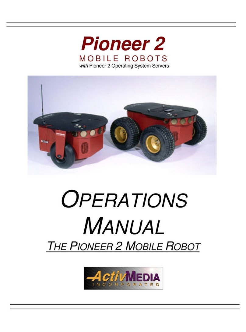
ActivMedia Robotics Pioneer 2 User manual

ActivMedia Robotics
ActivMedia Robotics MOBILEROBOTS Team AmigoBot-SH User manual
ActivMedia Robotics
ActivMedia Robotics AmigoBot User manual
ActivMedia Robotics
ActivMedia Robotics Pioneer 2 Arm User manual

ActivMedia Robotics
ActivMedia Robotics AmigoBot User manual
