Ada Ez Pro User manual
700402
Rev. B, 10/30/12
© 2012 ADA EZ. ALL RIGHTS RESERVED.
1 of 15
Quick-Start Guide
ADA EZ Pro
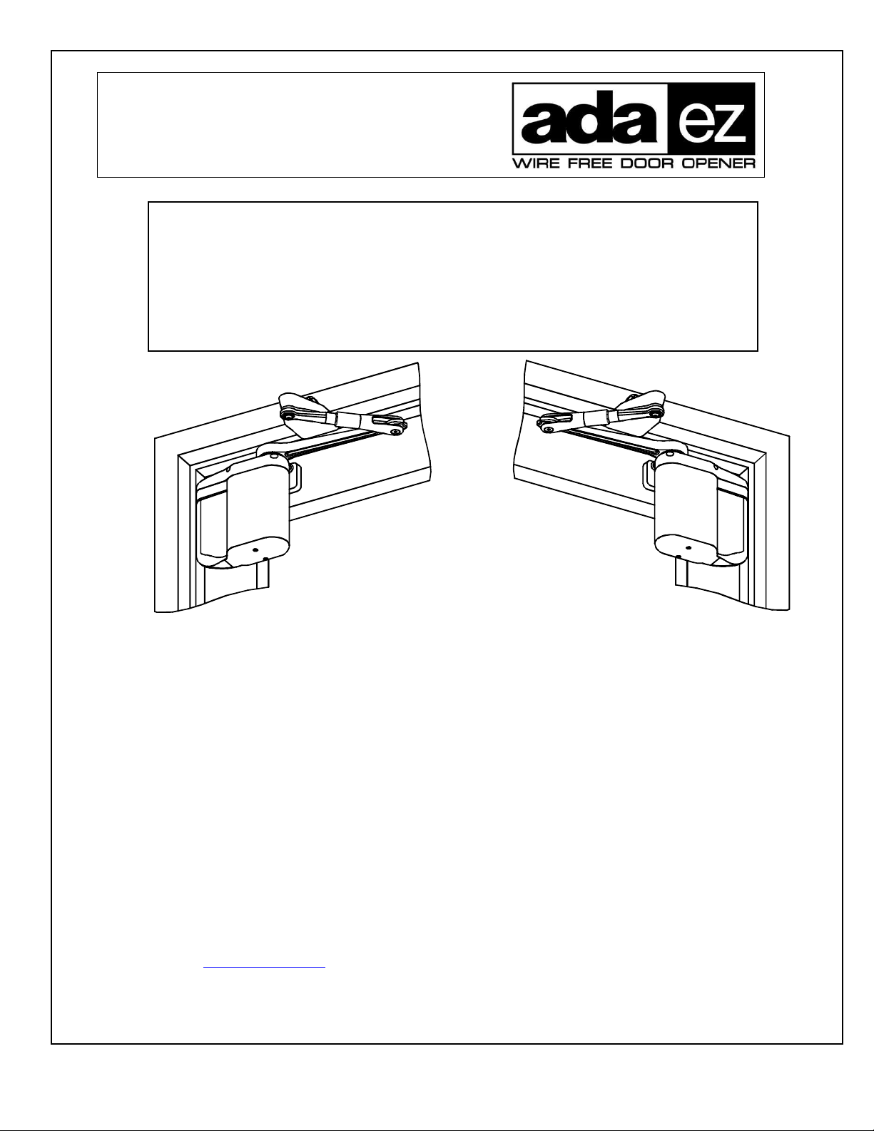
Push-Side Operator Quick-Start Guide
700402
Rev. , 10/30/12
PUSH-SIDE APPLICATION
(RIGHT HAND DOOR SHOWN)
PUSH-SIDE APPLICATION
(LEFT HAND DOOR SHOWN)
Thi manual provide quick-reference in truction for in talling and operating the pu h- ide ADA EZ wing
door operator. Prior to performing the e in truction thoroughly review the following information in
document number 70002, “ADA EZ Pro In tallation and Operating In truction :”
•
Sy tem De cription
•
Detailed operator programming in truction
•
Prerequi ite
•
Replacing the battery pack fu e
•
Precaution
•
Cu tomizing the operator etting
•
Control and indicator
•
In talling door decal
•
In talling the optional plug-in tran former
•
Detailed clo eout in truction
•
In talling the pu hbutton witche
•
Wiring
•
Linking the RF pu hbutton
•
Replacement part
• Trouble hooting recommendation • Adju ting door pring ten ion
To obtain the late t manual and template revi ion or to view in tallation and programming video
go to www.ADAEZ.com. For technical upport call (877) 232-3987.
700402
Rev. B, 10/30/12
© 2012 ADA EZ. ALL RIGHTS RESERVED.
2 of 15
Quick-Start Guide
TABLE OF CONTENTS
1.1 In talling the Operator Mounting Template ................................................................................................. 2
1.2 Mounting the Door Arm Pivot Bracket ........................................................................................................ 3
1.3 In talling the Door Arm Pivot ...................................................................................................................... 5
1.4 In talling the Operator Mounting Bracket and Cover .................................................................................. 6
1.5 In talling the Door Arm ............................................................................................................................... 9
1.6 In talling the Optional Plug-In Tran former .............................................................................................. 10
1.7 Programming the Operator......................................................................................................................... 14
1.8 Initializing the Remote Control .................................................................................................................. 15
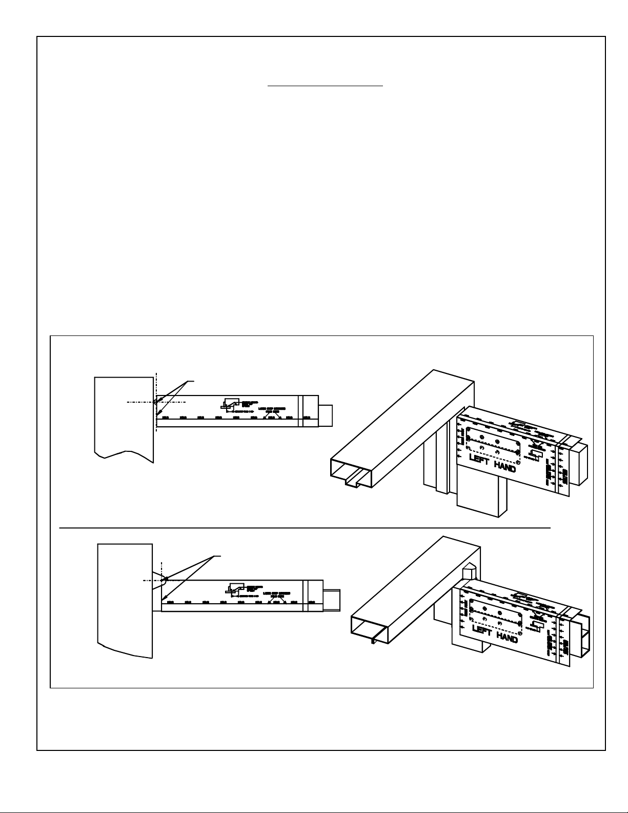
1.1 Installing the Operator Mounting Template
1.1.1 If the door i an aluminum torefront door, EXAMINE the top rail and, when drilling the mounting
hole , ENSURE the following:
• Do not drill into the top rail web
• Do not drill into the rail-to- tile tie rod( )
• Do not drill into the rail-to- tile junction
1.1.2 Refer to Figure 1, and ALIGN the operator mounting template to the centerline of the butt hinge,
center pivot, or off et pivot a applicable.
Figure 1. Installing the Operator Mounting Template
ALIGN TEMPLATE WITH
HINGE CENTERLINE
TOP VIEW -
BUTT HINGE HUNG DOOR
TOP VIEW - OFFSET PIVOT
ALIGN TEMPLATE
WITH PIVOT CENTERLINE
EZ045
700402
Rev. B, 10/30/12
© 2012 ADA EZ. ALL RIGHTS RESERVED.
3 of 15
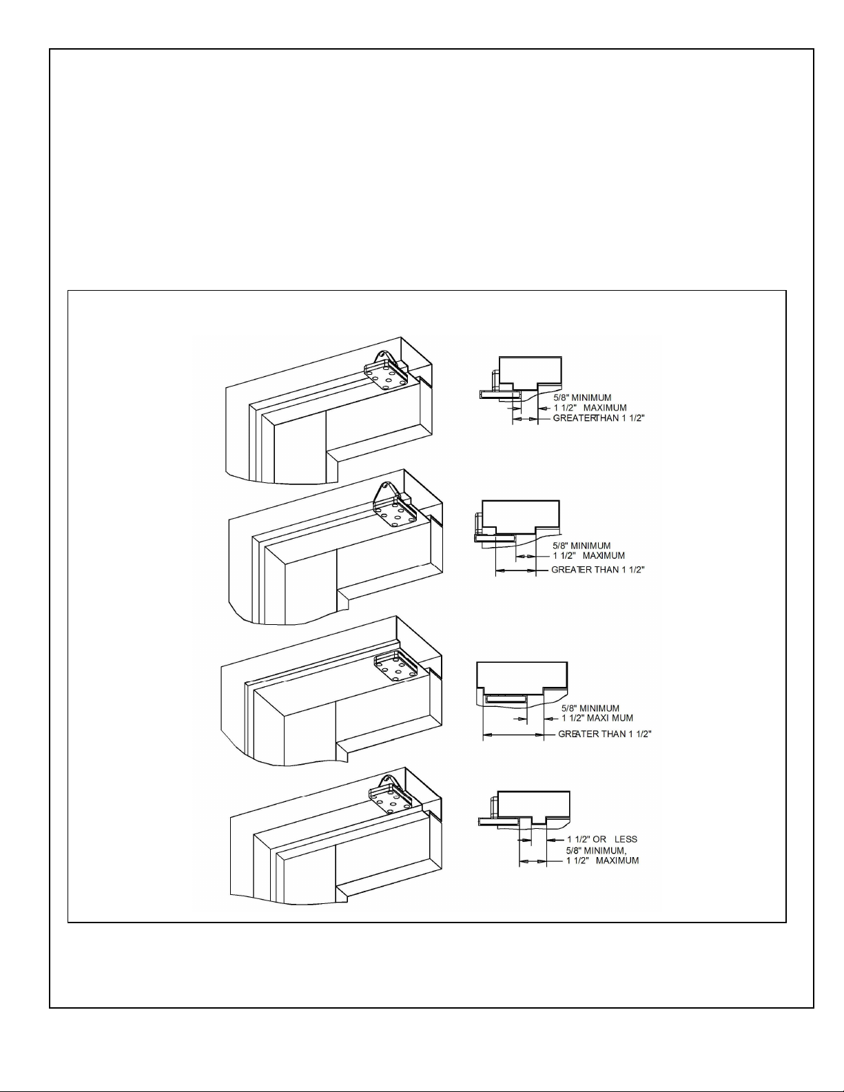
1.2 Mounting the Door Arm Pivot racket
1.2.1 Refer to Figure 2, and DETERMINE the orientation of the door arm pivot bracket a nece ary to
en ure the following (a applicable):
• If the door i a typical in tallation, the vertical upport will et flu h again t the face of the
frame header.
• If the door i a large reveal in tallation, the bracket will mount to the under ide of the frame
header.
• The edge of the bracket will be between
5
/
8
″ (15.87 mm) and 1
1
/
2
″ (38.1 mm) from the face of
door.
Figure 2. Mounting the Door Arm Pivot racket
700402
Rev. B, 10/30/12
© 2012 ADA EZ. ALL RIGHTS RESERVED.
4 of 15
CAUTION
To en ure proper in tallation, the door arm pivot bracket mu t be fa tened to the under ide of the header
frame and to the face of the header frame with at least three fa tener .
NOTE
When attempting to in tall the rivnut to the under ide of the door frame it may be nece ary to remove the
door top.
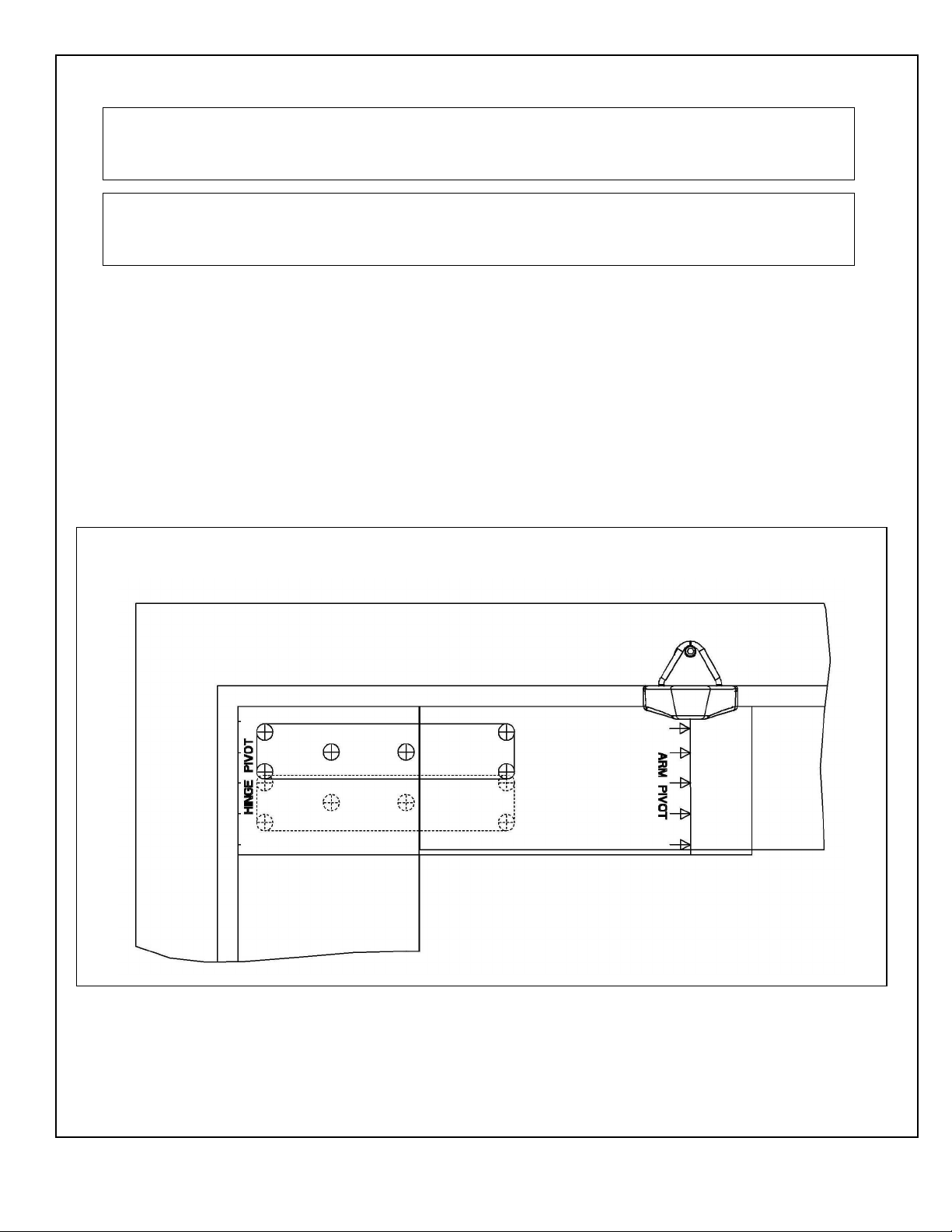
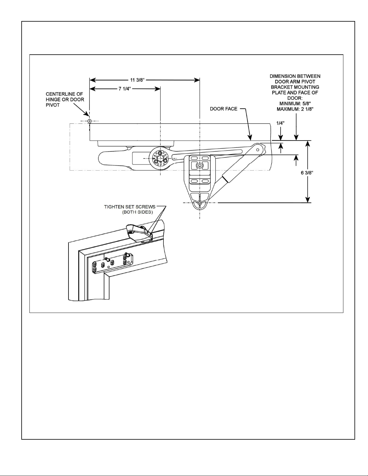
1.2.2 Refer to Figure 3 and, u ing a center punch, MARK the door arm pivot bracket hole location .
1.2.3 If the door frame i aluminum and rivnut mu t be in talled, PERFORM the following:
a. U ing a
25
/
64
″ drill, DRILL the door arm pivot bracket hole .
b. U ing a rivnut tool, INSTALL the ¼-20 teel rivnut .
c. INSTALL and TIGHTEN the three (minimum) ¾″ (19.05 mm) ocket head cap crew
ecuring the door arm pivot bracket to the under ide and face of the frame header.
1.2.4 If the door frame i wood, PERFORM the following:
a. U ing a
5
/
32
″ (3.97 mm) drill, DRILL the door arm pivot bracket pilot hole .
b. INSTALL and TIGHTEN the three #14 x 1 ¼″ wood crew (minimum) ecuring the door
arm pivot bracket to the under ide and face of the frame header.
Figure 3. Mounting the Door Arm Pivot racket
700402
Rev. B, 10/30/12
© 2012 ADA EZ. ALL RIGHTS RESERVED.
5 of 15
1.3 Installing the Door Arm Pivot
1.3.1 Refer to Figure 4, and SLIDE the door arm pivot over the door arm pivot bracket.
1.3.2 ENSURE that the dimen ion from the face of the door to the centerline of the door arm mounting
hole i 6
3
/
8
″ (161.92 mm).
1.3.3 TIGHTEN the four et crew ecuring the door arm pivot to the door arm pivot bracket.
Figure 4. Installing the Door Arm Pivot
700402
Rev. B, 10/30/12
© 2012 ADA EZ. ALL RIGHTS RESERVED.
6 of 15
1.4 Installing the Operator Mounting racket and Cover
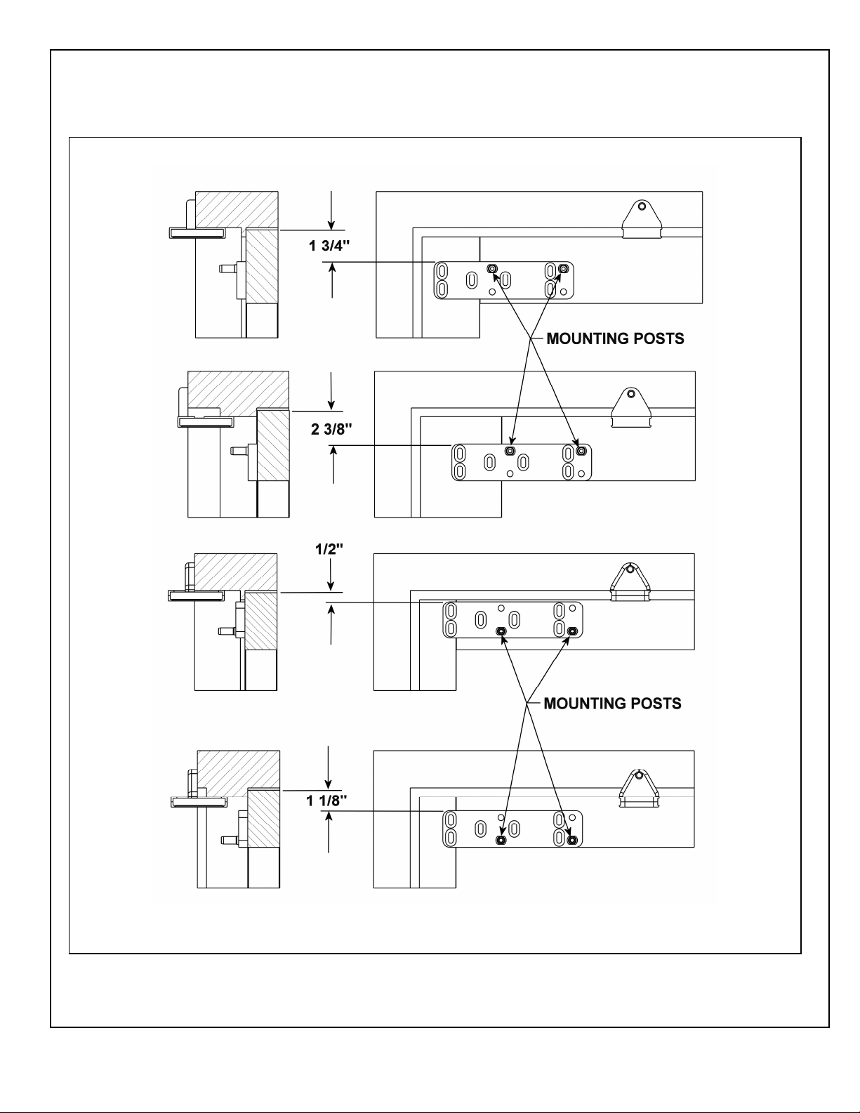
1.4.1 Refer to Figure 5, and DETERMINE the proper operator mounting bracket location.
Figure 5. Determining the Operator Mounting racket Location

700402
Rev. B, 10/30/12
© 2012 ADA EZ. ALL RIGHTS RESERVED.
7 of 15
1.4.2 If the door frame i aluminum and rivnut mu t be in talled, PERFORM the following:
• U ing a
25
/
64
″ (9.92 mm) drill, DRILL the operator mounting bracket hole .
1.4.3 U ing a rivnut tool, INSTALL the ¼-20 teel rivnut .
NOTE
Some door in tallation may require ex nut and bolt fa tener .
1.4.4 If the door frame i wood, PERFORM the following:
• U ing a
5
/
32
″ (3.97 mm) drill, DRILL the operator mounting bracket hole .
1.4.5 INSTALL a wa her onto each of the four (minimum) ¾″ (19.05 mm) ocket head operator
mounting bracket cap crew .
1.4.6 INSTALL, but do not TIGHTEN the ocket head cap crew ecuring the operator mounting
bracket to the door.
1.4.7 ADJUST the operator mounting bracket a follow :
• If the upper fold on the operator mounting template wa u ed (large top mounting), ADJUST
the bracket o that there i 2
3
/
8
″ (60.32 mm) pace between the top of the bracket and the top of
the door.
• If the lower fold on the operator mounting template wa u ed ( tandard mounting), ADJUST
the bracket o that there i 1¾″ (44.45mm) pace between the top of the bracket and the top of
the door.
• If the narrow tile door mounting location wa u ed ( olid line on operator mounting template),
ADJUST the bracket o that there i
1
/
2
″ (12.7 mm) pace between the top of the bracket and
the top of the door.
1.4.8 TIGHTEN the ocket head cap crew ecuring the operator mounting bracket to the door.
NOTE
The operator mounting bracket include four threaded hole that accept the operator mounting pin . The
lower et of two threaded hole i u ed when the operator i in talled on a narrow-rail door. The upper et
of two threaded hole i u ed when the operator i in talled on a medium- or wide-rail door.
1.4.9 Refer to Figure 5 and PERFORM one of the following a applicable:
• If the operator i being mounted to a narrow rail door, TIGHTEN the operator mounting pin
into the lower threaded hole in the mounting bracket u ing a
7
/
16
″ (11.112 mm) box wrench or
large adju table wrench.
• If the operator i being mounted to a wide or medium rail door, TIGHTEN the operator
mounting pin into the upper threaded hole in the mounting bracket u ing a
7
/
16
″ (11.112 mm)
box wrench or large adju table wrench.
1.4.10 Refer to Figure 6, and INSTALL the operator mounting bracket cover over the operator mounting
bracket.
1.4.11 REMOVE the two cap crew ecuring the operator bottom cover to the operator.
1.4.12 REMOVE the bottom cover from the operator.
1.4.13 SLIDE the battery pack from the operator and REMOVE the battery pack.
1.4.14 REMOVE the dre cover from the operator.

700402
Rev. B, 10/30/12
© 2012 ADA EZ. ALL RIGHTS RESERVED.
8 of 15
WARNING
To avoid inadvertent activation of the operator during connection of the door arm, the battery pack hould
not be in talled until after the door arm i connected.
1.4.15 With the battery pack facing the jamb, POSITION the operator onto the operator mounting pin .
ENSURE the operator doe not lide off the mounting pin .
1.4.16 INSTALL and TIGHTEN the two ¼-20 X 1½″ ocket head cap crew ecuring the operator to the
operator mounting pin .
Figure 6. Installing Operator Mounting racket Cover
OPERATOR MOUNTING
BRACKET COVER
EZ021

700402
Rev. B, 10/30/12
© 2012 ADA EZ. ALL RIGHTS RESERVED.
9 of 15
1.5 Installing the Door Arm
1.5.1 Refer to Figure 7, and, with the door arm coupling crew facing up and the door arm again t the
door rail, POSITION the larger end of the door arm onto the operator output haft.
CAUTION
The door arm coupling i a two-piece tapered coupling. In order to draw the coupling halve together
evenly the three door arm coupling crew mu t be tightened evenly (one quarter turn at a time) until fully
tight.
1.5.2 With the door arm touching the face of the door, TIGHTEN the door arm coupling crew evenly
(one quarter turn at a time) until fully tight.
Figure 7. Installing the Door Arm

700402
Rev. B, 10/30/12
© 2012 ADA EZ. ALL RIGHTS RESERVED.
10 of 15
1.5.3 HOLD the elbow of the door arm again t the face of the door, and THREAD the adju table door
arm end link into the door arm a nece ary to align the end link mounting hole with the door arm
pivot mounting hole.
1.5.4 If the door arm end link doe not align with the door arm pivot mounting hole and there i no
available travel on the threaded end link, PERFORM the following:
• LOOSEN the ocket head cap crew ecuring the door arm pivot to the door arm pivot bracket.
• SLIDE the door arm pivot a nece ary to align the door arm end link with the door arm pivot
mounting hole.
• TIGHTEN the ocket head cap crew ecuring the door arm pivot to the door arm pivot
bracket.
NOTE
In order to apply a preload to the door, the door arm mu t be threaded into the door arm three revolution .
1.5.5 THREAD the adju table door arm end link into the door arm three revolution .
1.5.6 INSTALL the wa her provided onto the top of the door arm end link, and TIGHTEN the
5
/
16
-18 X
7
/
8
″ button-head cap crew ecuring the door arm end link to the door arm pivot bracket.
1.5.7 CYCLE the door everal time , and ENSURE that the door open and clo e moothly.
1.5.8 SLIDE the dre cover onto the operator.
1.5.9 CONNECT the battery pack connector plug to the operator.
1.5.10 SLIDE the battery pack onto the operator, and ENSURE that the battery pack wire will not
interfere with the operator cover.
1.6 Installing the Optional Plug-In Transformer
NOTE
If po ible, the tran former wiring hould be routed again t the door trim molding.
1.6.1 ROUTE tran former wiring to a 110-VAC outlet, but do not plug tran former into the outlet.
NOTE
An optional plug-in tran former i recommended in in tallation where the automatic door-opening feature
will be u ed frequently. The optional plug-in tran former i REQUIRED for in tallation where Power
Clo e and/or Pu h and Go feature are enabled.
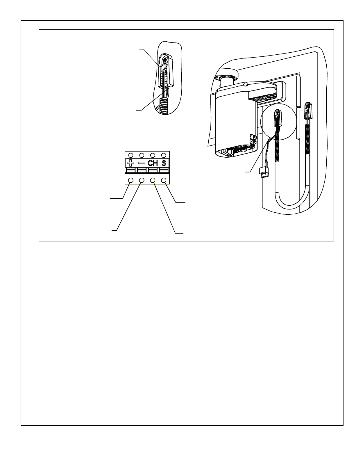
1.6.2 Refer To Figure 8, and ROUTE wire through armored cable end link . MOUNT the door cord end
link a follow :
• MOUNT one end link in the area behind or next to the battery pack.
• MOUNT the other end link on or next to the door frame.
700402
Rev. B, 10/30/12
© 2012 ADA EZ. ALL RIGHTS RESERVED.
11 of 15
Figure 8. Routing Wires through Cable End Links
SEE DETAIL A
ROUTE WIRE INTO
END LINK FROM
FRONT
ROUTE WIRE THROUGH
EXIT AT BOTTOM
SIGNAL INPUT
CHARGER INPUT
GROUND (COMMON) INPUT
24VDC (POSITIVE) INPUT
EZ0 1
DETAIL A

700402
Rev. B, 10/30/12
© 2012 ADA EZ. ALL RIGHTS RESERVED.
12 of 15
1.6.3 Refer to Figure 9, and PLUG connector into receptacle on battery pack.
1.6.4 Refer to Figure 10, and VERIFY that the LED indicator light GREEN.
Figure 9. Plugging the Connector into the Receptacle
CONNECTOR COVER
CONNECTOR PLUG
CONNECTOR RECEPTACLE
EZ0 0
Figure 10. Verifying that the LED Illuminates
LED INDICATOR
ADAEZ 0
700402
Rev. B, 10/30/12
© 2012 ADA EZ. ALL RIGHTS RESERVED.
13 of 15
1.6.5 Refer To Figure 11, and INSTALL receptacle cover onto battery pack.
Figure 11. Plugging the Receptacle Cover onto the attery Pack
EZ0 2

700402
Rev. B, 10/30/12
© 2012 ADA EZ. ALL RIGHTS RESERVED.
14 of 15
1.7 Programming the Operator
1.7.1 Refer to Figure 12, and, at the ba e of the controller, PRESS and HOLD the “SELECT” and
“ENTER” pu hbutton for three econd . The following hall occur:
• The operator hall enter program mode.
• The four LED on the circuit board hall repeatedly fla h green.
• The “CLS” po ition LED hall illuminate red and remain lit.
1.7.2 With the door in the clo ed po ition, PRESS the “ENTER” pu hbutton. The following hall occur:
• The “CLS” po ition LED hall fla h green.
• The “OP” (open) po ition LED hall illuminate red indicating that the operator i ready for
input.
• The LED hall illuminate green once data ha been tored for thi parameter.
1.7.3 With the door in the clo ed po ition, PRESS the “ENTER” pu hbutton.
1.7.4 OPEN the door to it fully open po ition.
1.7.5 With the door in the fully open po ition, PRESS the “ENTER” pu hbutton. The following hall
occur:
• The “OP” po ition LED hall fla h green.
• The “AUTO SETUP” po ition LED hall illuminate red indicating that the operator i ready for
input.
• The LED hall illuminate green once data ha been tored for thi parameter.
1.7.6 With the door in the fully clo ed po ition, PRESS the “ENTER” pu hbutton. The following hall
occur:
Figure 12. Door Controller Circuit oard Controls and Indicators
TUNING POTENTIOMETER
DS11
DS12 TERMINAL BLOCK FOR
OPTIONAL TRANSFORMER
ADJUSTMENT INDICATOR LEDs
ADAQS07A
DS10 DYNAMIC BRAKING LED
DS POWER CLOSE LED
DS9 PUSH AND GO LED

700402
Rev. B, 10/30/12
© 2012 ADA EZ. ALL RIGHTS RESERVED.
15 of 15
• The door hall open quickly and then clo e.
• The “AUTO SETUP” led hall illuminate green.
1.7.7 PRESS and HOLD the “ENTER” pu hbutton for three econd . The following hall occur:
• The “AUTO SETUP” led hall go out.
• The econd LED (not labeled) hall fla h green.
• The door hall be tuned.
1.7.8 To re et the controller, PERFORM the following:
a. PRESS and HOLD the “RESET” pu hbutton.
b. PRESS and HOLD the “ENTER” pu hbutton.
c. RELEASE the “RESET” pu hbutton.
1.7.9 If further door adju tment are nece ary, refer to document number 70001, “ADA EZ In tallation
and Operating In truction ,” and ADJUST a needed.
1.8 Initializing the Remote Control
1.8.1 To link an RF witch with a door controller, PERFORM the following:
a. PRESS and HOLD the “LEARN” pu hbutton on the controller until LED DS8 through DS11
fla h green. The controller hall remain in the learn mode for 20 econd or until the RF ignal
i received.
b. PUSH the RF pu hbutton. LED DS7 hall fla h green indicating that the operator accepted thi
RF pu hbutton.
c. REPEAT tep 1.8.1.a. and 1.8.1.b. a nece ary for up to eight ADA EZ tran mitter .
1.8.2 To remove all RF pu hbutton from memory, PERFORM the following:
a. While pre ing and holding the “LEARN” pu hbutton on the controller, PRESS and
RELEASE the “RESET” pu hbutton.
Other manuals for Pro
1
Table of contents
Other Ada Ez Door Opening System manuals


Popular Door Opening System manuals by other brands


Assa Abloy
Assa Abloy Norton 6300 Series installation instructions

Dorma
Dorma ES 200 Mounting instructions and Instruction manual

DITEC
DITEC Entrematic Hurricane DS20 Installation and service manual

Bohle
Bohle Santos instruction manual

cinetto
cinetto PS19 Assembly instructions

Assa Abloy
Assa Abloy Rixson Smok-Chek VI Installation and instruction manual

Falcon
Falcon Ferme-Porte SC60 series installation instructions

Metaflex
Metaflex Medicare EI1 2.0 installation manual

Detex
Detex AO19 Quick install guide

Häfele
Häfele XL Pocket Door Slide System Mounting instructions

quiko
quiko QK-RADAROMNI user manual

BFT
BFT BOTTICELLI SMART BT A 850-1250 Installation and user manual