ADLINK Technology DLAP-3000 Series User manual

Leading EDGE COMPUTING
DLAP-3000/3100-CF Series
Embedded System supporting MXM Graphics Module with
8th/9th Generation Intel® Core™ i7/i5/i3 in LGA1151 Socket
User’s Manual
Manual Rev.: 1.1
Revision Date: April 19, 2021
Part No: 50M-00019-1010

ii
Leading EDGE COMPUTING
Revision History
Revision Release Date Description of Change(s)
1.0 2020-12-23 Initial release
1.1 2021-04-19
Add MXM cooler for RTX5000 and
500W power supply; update
specifications and DisplayPort BIOS
settings

Preface iii
DLAP-3000/3100-CF
Preface
Copyright © 2020, 2021 ADLINK Technology Inc.
This document contains proprietary information protected by copy-
right. All rights are reserved. No part of this manual may be repro-
duced by any mechanical, electronic, or other means in any form
without prior written permission of the manufacturer.
Disclaimer
The information in this document is subject to change without prior
notice in order to improve reliability, design, and function and does
not represent a commitment on the part of the manufacturer.
In no event will the manufacturer be liable for direct, indirect, spe-
cial, incidental, or consequential damages arising out of the use or
inability to use the product or documentation, even if advised of
the possibility of such damages.
Environmental Responsibility
ADLINK is committed to fulfill its social responsi-
bility to global environmental preservation
through compliance with the European Union's
Restriction of Hazardous Substances (RoHS)
directive and Waste Electrical and Electronic
Equipment (WEEE) directive. Environmental pro-
tection is a top priority for ADLINK. We have
enforced measures to ensure that our products,
manufacturing processes, components, and raw
materials have as little impact on the environment as possible.
When products are at their end of life, our customers are encour-
aged to dispose of them in accordance with the product disposal
and/or recovery programs prescribed by their nation or company.
Battery Labels (for products with battery)
ᘄ㟁ụㄳᅇᨲ

iv Preface
Leading EDGE COMPUTING
California Proposition 65 Warning
WARNING: This product can expose you to chemicals
including acrylamide, arsenic, benzene, cadmium,
Tris(1,3-dichloro-2-propyl) phosphate (TDCPP), 1,4-
Dioxane, formaldehyde, lead, DEHP, styrene, DINP, BBP, PVC,
and vinyl materials, which are known to the State of California to
cause cancer, and acrylamide, benzene, cadmium, lead, mercury,
phthalates, toluene, DEHP, DIDP, DnHP, DBP, BBP, PVC, and
vinyl materials, which are known to the State of California to cause
birth defects or other reproductive harm. For more information go
to www.P65Warnings.ca.gov.
Trademarks
Product names mentioned herein are used for identification pur-
poses only and may be trademarks and/or registered trademarks
of their respective companies.
Conventions
Take note of the following conventions used throughout this
manual to make sure that users perform certain tasks and
instructions properly.
NOTE:
NOTE:
Additional information, aids, and tips that help users perform
tasks.
CAUTION:
Information to prevent minor physical injury, component dam-
age, data loss, and/or program corruption when trying to com-
plete a task.
ATTENTION: Informations destinées à prévenir les blessures
corporelles mineures, les dommages aux composants, la perte
de données et/ou la corruption de programme lors de l'exécu-
tion d'une tâche.
WARNING:
Information to prevent serious physical injury, component
damage, data loss, and/or program corruption when trying to
complete a specific task.
AVERTISSEMENT: Informations destinées à prévenir les bles-
sures corporelles graves, les dommages aux composants, la
perte de données et/ou la corruption de programme lors de
l'exécution d'une tâche spécifique.

Table of Contents v
DLAP-3000/3100-CF
Table of Contents
Preface.................................................................................... iii
List of Tables......................................................................... vii
List of Figures........................................................................ ix
1 Introduction ........................................................................ 1
1.1 Overview.............................................................................. 1
1.2 Features............................................................................... 1
1.3 Packing List ......................................................................... 2
1.4 Optional Accessories ........................................................... 3
2 Specifications..................................................................... 5
2.1 DLAP-3000-CF .................................................................... 5
2.2 DLAP-3100-CF .................................................................. 11
2.3 DLAP-3000/3100-CF Functional Block Diagrams ............. 17
2.4 Display Options.................................................................. 19
2.5 Mechanical Dimensions..................................................... 20
3 System Layout.................................................................. 25
3.1 Front Panel ........................................................................ 25
3.2 Internal I/O Connectors...................................................... 33
4 Getting Started ................................................................. 55
4.1 Installing 2.5” Storage........................................................ 56
4.2 Installing an M.2 Module.................................................... 58
4.3 Installing MXM P1000/P2000/T1000 Module .................... 62
4.4 Installing MXM P3000/P5000/RTX3000/RTX5000 Module 66
4.5 Mounting ............................................................................ 72
4.6 Driver Installation ............................................................... 74

vi Table of Contents
Leading EDGE COMPUTING
A Appendix: Power Consumption .......................................75
A.1 Power Consumption Reference ......................................... 75
B Appendix: Resource Mapping..........................................77
B.1 BIOS Mapping in SPI ROM................................................ 77
B.2 PCI/PCIe Devices .............................................................. 78
B.3 IRQ Lines (APIC Mode) ..................................................... 79
B.4 IRQ Lines (PIC Mode)........................................................ 80
B.5 System Memory Mapping .................................................. 81
B.6 System I/O Mapping .......................................................... 82
B.7 PCI/PCIe Interrupt Routing Mapping ................................. 83
B.8 SMBus Slave Address Mapping ........................................ 84
C Appendix: BIOS Setup.......................................................85
C.1 BIOS Setup Menu .............................................................. 85
C.2 Menu Structure .................................................................. 87
C.3 Main Menu ......................................................................... 89
C.4 Advanced Menu ................................................................. 92
C.5 Chipset............................................................................. 110
C.6 Security............................................................................ 117
C.7 Boot ................................................................................. 118
C.8 Save & Exit ...................................................................... 119
D Appendix: DisplayPort BIOS Settings ...........................121
D.1 MXM P1000/P2000/T1000/RTX3000/RTX5000 .............. 121
D.2 MXM P3000/P5000.......................................................... 122
E Appendix: Digital Input/Output Function Library .........123
Important Safety Instructions............................................. 125
Consignes de Sécurité Importante.................................... 127
Getting Service.................................................................... 131

List of Tables vii
DLAP-3000/3100-CF
List of Tables
Table 2-1: Maximum Display Resolution ................................... 19
Table 3-1: I/O Legend................................................................ 27
Table 3-2: Digital Input/Output Connector Pin Definition ........... 29
Table 3-3: Active/Link LED Indicators........................................ 31
Table 3-4: Speed LED Indicators............................................... 31
Table 3-5: D-Sub 9-pin Signal Function of COM Ports.............. 32
Table 3-6: Mainboard Connector Legend .................................. 35
Table 3-7: USB 2.0 Connector Pin Definition ............................ 37
Table 3-8: USB 3.2 Connector Pin Definition ............................ 38
Table 3-9: PCIe Power Connector Pin Definition....................... 39
Table 3-10: SATA Connector Pin Definition ................................ 39
Table 3-11: COM Connector Pin Definition ................................. 40
Table 3-12: CPU/System Fan Connector Pin Definition .............. 41
Table 3-13: GPU Fan Connector Pin Definition........................... 42
Table 3-14: Audio Connector Pin Definition................................. 43
Table 3-15: COM1 RS-232/CCtalk Selection Jumper ................. 44
Table 3-16: Case Open Jumper .................................................. 44
Table 3-17: ME Lock Jumper....................................................... 44
Table 3-18: Clear CMOS Jumper ................................................ 45
Table 3-19: BIOS WP Jumper ..................................................... 45
Table 3-20: Power-on Module Connector Pin Definition.............. 46
Table 3-21: DIO Connector Pin Definition ................................... 47
Table 3-22: 12V DC-in Connector Pin Definition ......................... 48
Table 3-23: PCB Edge Connector Pin Definition ......................... 52
Table 3-24: DB40 Connector Pin Definition................................. 53
Table A-1: DLAP-3000 Power Consumption.............................. 75
Table A-2: DLAP-3100 Power Consumption.............................. 76

viii List of Tables
Leading EDGE COMPUTING
This page intentionally left blank.

List of Figures ix
DLAP-3000/3100-CF
List of Figures
Figure 2-1: DLAP-3000-CF Functional Block Diagram .................... 17
Figure 2-2: DLAP-3100-CF Functional Block Diagram .................... 18
Figure 2-3: DLAP-3000-CF Front View ............................................ 20
Figure 2-4: DLAP-3100-CF Front View ............................................ 20
Figure 2-5: DLAP-3000/3100-CF Left Side View ............................. 21
Figure 2-6: DLAP-3000/3100-CF Right Side View........................... 21
Figure 2-7: DLAP-3000-CF Rear View............................................. 22
Figure 2-8: DLAP-3100-CF Rear View............................................. 22
Figure 2-9: DLAP-3000/3100-CF Top View ..................................... 23
Figure 3-1: DLAP-3000-CF Front Panel I/O..................................... 25
Figure 3-2: DLAP-3000-CF Rear Panel I/O ..................................... 25
Figure 3-3: DLAP-3100-CF Front Panel I/O..................................... 26
Figure 3-4: DLAP-3100-CF Rear Panel I/O ..................................... 26
Figure 3-5: Power-on Module........................................................... 27
Figure 3-6: Digital I/O Connector Pin Definition ............................... 29
Figure 3-7: Digital Input Circuit......................................................... 30
Figure 3-8: Digital Output Circuit...................................................... 30
Figure 3-9: COM Port Pin Definition................................................. 32
Figure 3-10: Mainboard Connectors (Top)......................................... 33
Figure 3-11: Mainboard Connectors (Rear) ....................................... 34
Figure 3-12: USB 2.0 Connector Pin Definition.................................. 37
Figure 3-13: USB 3.2 Connector Pin Definition.................................. 38
Figure 3-14: PCIe Power Connector Pin Definition............................ 39
Figure 3-15: SATAConnector Pin Definition....................................... 39
Figure 3-16: COM Connector Pin Definition....................................... 40
Figure 3-17: CPU/System Fan Connector Pin Definition ................... 41
Figure 3-18: GPU Fan Connector Pin Definition ................................ 42
Figure 3-19: Audio Connector Pin Definition...................................... 43
Figure 3-20: Multiple I/O Connector Pin Definition............................. 44
Figure 3-21: Power-on Module Connector Pin Definition................... 46
Figure 3-22: DIO Connector Pin Definition......................................... 47
Figure 3-23: 12V DC-in Connector Pin Definition .............................. 48
Figure 3-24: PCB Edge Connector Pin Definition .............................. 49
Figure 3-25: DB40 Connector Pin Definition ...................................... 52

xListofFigures
Leading EDGE COMPUTING
This page intentionally left blank.

Introduction 1
DLAP-3000/3100-CF
1 Introduction
1.1 Overview
The DLAP-3000/3100-CF series is an optimized computing plat-
form supporting performance-hungry workloads, such as deep
learning, with expandability options and active cooling for applica-
tions requiring very high levels of computing in a limited space.
The DLAP-3000/3100-CF series is one of the smallest embedded
GPU platforms (3.2 liters) with a low TDP reliable MXM GPU
design and scalable graphics processing ranging from Pascal to
Turing GPUs.
1.2 Features
XADLINK MXM Graphics module support (Type A/B, up to
120W)
X8th/9th Gen Intel® Core™ i7/i5/i3, Celeron® processors
XDual SODIMMs for up to 64GB DDR4 non-ECC memory
(CPU dependent)
X6x DisplayPort (2 from CPU, 4 from MXM)
X1x M.2 E key supporting 1630 or 2230 for Wi-Fi/Bluetooth
module
X1x M.2 B key supporting 2242 or 2280 for SATA storage
module
X1x M.2 M key supporting 2242 or 2280 for SATA/PCIe x4
storage module (DLAP-3100 only)
XReliable Molex type 12V DC-in connector
X1x Intel® i219-LM and 5x Intel® i210-AT (DLAP-3100 only)
X1x Intel® i219-LM and 3x Intel® i210-AT (DLAP-3000 only)

2Introduction
Leading EDGE COMPUTING
1.3 Packing List
Before unpacking, check the shipping carton for any damage. If
the shipping carton and/or contents are damaged, inform your
dealer immediately. Retain the shipping carton and packing mate-
rials for inspection. Obtain authorization from your dealer before
returning any product to ADLINK. Ensure that the following items
are included in the package.
X1x DLAP-3000/3100-CF Embedded Computer
XFasteners:
Z3x M3 screws, P-head, L4, Ni for M.2
(P/N: 33-03013-0040)
Z8x M3 screws, F-head, L4, Nylok for 2.5” storage bay
(P/N: 33-03103-1040)
Z2x M3 screws, I-head, L4, Nylok for MXM
(P/N: 33-03306-0040)
NOTE:
NOTE:
If the DLAP-3000/3100-CF does not have a pre-installed MXM
P3000/P5000/RTX3000/RTX5000, the following additional
installation items have been included.
X4x M3 Screw, I-head, L5, Ni (PN: 33-03320-0050)
X4x Washer 5.3 x 10 x 1.0, SUS (PN:33-90086-0000-A0)
X4x Rubber footpad (PN:39-00039-0000)

Introduction 3
DLAP-3000/3100-CF
1.4 Optional Accessories
XCPU cooler (P/N: 32-20495-0000)
XCPU cooler bracket (P/N: 32-50015-0100-A0)
XMXM cooler for P1000/P2000 (P/N: 32-20797-0200-A0)
XMXM cooler for P3000/P5000 (P/N: 32-20823-0020-A0)
XMXM cooler for T1000 (P/N: 32-20830-0200-A0)
XMXM cooler for RTX3000 (P/N: 32-20823-1100-A0)
XMXM cooler for RTX5000 (P/N: 32-20839-1000-A0)
X12V/240W power adaptor (P/N: 31-62164-0010-A0)
X500W power supply (12V/41.7A) (P/N: 91-95296-000E)
X
Wall mount bracket set (P/N: 34-34546-0000-A0) (2 required)
XWi-Fi Kit Intel® Wireless-AC 9260 non-vPRO
(P/N: 91-95266-0020)

4Introduction
Leading EDGE COMPUTING
This page intentionally left blank.

Specifications 5
DLAP-3000/3100-CF
2 Specifications
2.1 DLAP-3000-CF
Model
DLAP-
3000-CFP1 DLAP-
3000-CFP2 DLAP-
3000-CFT1 DLAP-
3000-CFT3 DLAP-
3000-CFT5
DLAP-3000-CFP12*
MXM
Support
EGX-MXM-
P1000
EGX-MXM-
P2000
EGX-MXM-
T1000
EGX-MXM-
RTX3000
EGX-MXM-
RTX5000
Processor
XIntel® Core™ i7-9700E, 2.6GHz, 12M Cache, 65W TDP,
LGA1151, DDR4 2666MHz support (8C/8T)
XIntel® Core™ i7-9700TE, 1.8GHz, 12M Cache, 35W TDP,
LGA1151, DDR4 2666MHz support (8C/8T)
XIntel® Core™ i5-9500E, 3.0GHz, 9M Cache, 65W TDP,
LGA1151, DDR4 2666MHz support (6C/6T)
XIntel® Core™ i5-9500TE, 2.2GHz, 9M Cache, 35W TDP,
LGA1151, DDR4 2666MHz support (6C/6T)
XIntel® Core™ i3-9100E, 3.1GHz, 6M Cache, 65W TDP,
LGA1151, DDR4 2400MHz support (4C/4T)
XIntel® Core™ i3-9100TE, 2.2GHz, 6M Cache, 35W TDP,
LGA1151, DDR4 2400MHz support (4C/4T)
XIntel® Core™ i7-8700, 3.2GHz, 12M Cache, 65W TDP,
LGA1151, DDR4 2666MHz support (6C/12T)
XIntel® Core™ i7-8700T, 2.4GHz 12M Cache, 35W TDP,
LGA1151, DDR4 2666MHz support (6C/12T)
XIntel® Core™ i5-8500, 3.0GHz, 9M Cache, 65W TDP,
LGA1151, DDR4 2666MHz support (6C/6T)
XIntel® Core™ i5-8500T, 2.1GHz, 9M Cache, 35W TDP,
LGA1151, DDR4 2666MHz support (6C/6T)
XIntel® Core™ i3-8100, 3.6GHz, 6M Cache, 65W TDP,
LGA1151, DDR4 2400MHz support (4C/4T)
XIntel® Celeron® G4900, 3.1GHz, 2M Cache, 54W TDP,
LGA1151, DDR4 2400MHz support (2C/2T)
XIntel® Celeron® G4900T, 2.9GHz, 2M Cache, 35W TDP,
LGA1151, DDR4 2400MHz support (2C/2T)
Chipset Intel® H310 Chipset
Memory Non-ECC DDR4 2666/2400MHz, 2x SODIMM, up to 64GB
(CPU dependent)

6 Specifications
Leading EDGE COMPUTING
I/O Interface
Display 6x DisplayPort (2 from CPU, 4 from MXM)
Ethernet 1x GbE (Intel® i219-LM), 3x GbE (Intel® i210-AT)
Serial Ports 1x RS-232/422/485, 1x RS-232
USB 4x USB 3.2 Gen1 x1 ports, 4x USB 2.0 ports
Audio
Default: w/o Audio
Option 1: Mic-in, Line-out, Line-in
Option 2: Mic-in, L/R speaker-out (6W + 6W)
Option 3: Line-in, L/R speaker-out (6W + 6W)
M.2 1x M.2 E key supporting 1630 or 2230 for Wi-Fi/BT module
1x M.2 B key supporting 2242 or 2280 for SATA storage module
eSIM Optional
DI/O
Default: w/o DIO
Option: 1x DI/DO with 4 in, 4 out
Note: Optional DIO, Audio and TPM 2.0 must be chosen
together
TPM 2.0 Default: no TPM
Storage
SATA 2x 2.5" SATA 6Gb/s external drive bays
1x SATA 6Gb/s signal via M.2 B key connector
Physical
Dimensions 235 x 182 x 75mm (W x D x H, without foot pads)
Mounting Optional wall-mount bracket
Power Supply
DC Input DC 12V input (Molex DC-in jack)
AC Input Optional: 240W (12V/20A) AC/DC adapter
Optional: 500W (12V/41.7A) AC/DC power supply
Model
DLAP-
3000-CFP1 DLAP-
3000-CFP2 DLAP-
3000-CFT1 DLAP-
3000-CFT3 DLAP-
3000-CFT5
DLAP-3000-CFP12*

Specifications 7
DLAP-3000/3100-CF
Environmental
Operating
Temperature
0°C to 50°C (W/MXM, W/SSD, excluding EGX-MXM-RTX5000)
0°C to 40°C (EGX-MXM-RTX5000)
Storage
Temperature -20°C to 70°C
Humidity 5% to 95%, non-condensing
Vibration
Operating: 2Grms, 5-500Hz, 3 axes
Package (non operating): 3.44Grms, 10-1000Hz, 3 axes (w/
MXM, w/SSD)
Shock Operating and Package (non operating): 30G, 11ms duration,
half-sine (w/MXM, w/SSD)
EMC EN55032/35, EN61000-6-2/-4, CE, FCC Part 15B Class B
Safety UL/cUL and CB
Model
DLAP-
3000-CFP1 DLAP-
3000-CFP2 DLAP-
3000-CFT1 DLAP-
3000-CFT3 DLAP-
3000-CFT5
DLAP-3000-CFP12*

8 Specifications
Leading EDGE COMPUTING
Model DLAP-3000-CFP3 DLAP-3000-CFP5
DLAP-3000-CFP35*
MXM Support EGX-MXM-P3000 EGX-MXM-P5000
Processor
XIntel® Core™ i7-9700E, 2.6GHz, 12M Cache, 65W TDP,
LGA1151, DDR4 2666MHz support (8C/8T)
XIntel® Core™ i7-9700TE, 1.8GHz, 12M Cache, 35W
TDP, LGA1151, DDR4 2666MHz support (8C/8T)
XIntel® Core™ i5-9500E, 3.0GHz, 9M Cache, 65W TDP,
LGA1151, DDR4 2666MHz support (6C/6T)
XIntel® Core™ i5-9500TE, 2.2GHz, 9M Cache, 35W TDP,
LGA1151, DDR4 2666MHz support (6C/6T)
XIntel® Core™ i3-9100E, 3.1GHz, 6M Cache, 65W TDP,
LGA1151, DDR4 2400MHz support (4C/4T)
XIntel® Core™ i3-9100TE, 2.2GHz, 6M Cache, 35W TDP,
LGA1151, DDR4 2400MHz support (4C/4T)
XIntel® Core™ i7-8700, 3.2GHz, 12M Cache, 65W TDP,
LGA1151, DDR4 2666MHz support (6C/12T)
XIntel® Core™ i7-8700T, 2.4GHz 12M Cache, 35W TDP,
LGA1151, DDR4 2666MHz support (6C/12T)
XIntel® Core™ i5-8500, 3.0GHz, 9M Cache, 65W TDP,
LGA1151, DDR4 2666MHz support (6C/6T)
XIntel® Core™ i5-8500T, 2.1GHz, 9M Cache, 35W TDP,
LGA1151, DDR4 2666MHz support (6C/6T)
XIntel® Core™ i3-8100, 3.6GHz, 6M Cache, 65W TDP,
LGA1151, DDR4 2400MHz support (4C/4T)
XIntel® Celeron® G4900, 3.1GHz, 2M Cache, 54W TDP,
LGA1151, DDR4 2400MHz support (2C/2T)
XIntel® Celeron® G4900T, 2.9GHz, 2M Cache, 35W TDP,
LGA1151, DDR4 2400MHz support (2C/2T)
Chipset Intel® H310 Chipset
Memory Non-ECC DDR4 2666/2400MHz, 2x SODIMM, up to 64GB
(CPU dependent)

Specifications 9
DLAP-3000/3100-CF
I/O Interface
Display 6x DisplayPort (2 from CPU, 4 from MXM)
Ethernet 1x GbE (Intel® i219-LM), 3x GbE (Intel® i210-AT)
Serial Ports 1x RS-232/422/485, 1x RS-232
USB 4x USB 3.2 Gen1 x1 ports, 4x USB 2.0 ports
Audio
Default: w/o Audio
Option 1: Mic-in, Line-out, Line-in
Option 2: Mic-in, L/R speaker-out (6W + 6W)
Option 3: Line-in, L/R speaker-out (6W + 6W)
M.2
1x M.2 E key supporting 1630 or 2230 for Wi-Fi/BT module
1x M.2 B key supporting 2242 or 2280 for SATA storage
module
eSIM Optional
DI/O
Default: w/o DIO
Option: 1x DI/DO with 4 in, 4 out
Note: Optional DIO, Audio and TPM 2.0 must be chosen
together
TPM 2.0 Default: no TPM
Storage
SATA 2x 2.5" SATA 6Gb/s external drive bays
1x SATA 6Gb/s signal via M.2 B key connector
Physical
Dimensions 235 x 182 x 75mm (W x D x H, without foot pads)
Mounting Optional wall-mount bracket
Power Supply
DC Input DC 12V input (Molex DC-in jack)
AC Input Optional: 240W (12V/20A) AC/DC adapter
Optional: 500W (12V/41.7A) AC/DC power supply
Model DLAP-3000-CFP3 DLAP-3000-CFP5
DLAP-3000-CFP35*

10 Specifications
Leading EDGE COMPUTING
Environmental
Operating
Temperature
0°C to 50°C (W/MXM, W/SSD, excluding EGX-MXM-
RTX5000)
0°C to 40°C (EGX-MXM-RTX5000)
Storage
Temperature -20°C to 70°C
Humidity 5% to 95%, non-condensing
Vibration
Operating: 2Grms, 5-500Hz, 3 axes
Package (non operating): 3.44Grms, 10-1000Hz, 3 axes (w/
MXM, w/SSD)
Shock Operating and Package (non operating): 30G, 11ms duration,
half-sine (w/MXM, w/SSD)
EMC EN55032/35, EN61000-6-2/-4, CE, FCC Part 15B Class B
Safety UL/cUL and CB
NOTE:
NOTE:
Models marked with “*” do not include an MXM graphics module.
Model DLAP-3000-CFP3 DLAP-3000-CFP5
DLAP-3000-CFP35*
This manual suits for next models
6
Table of contents
Other ADLINK Technology Industrial PC manuals
ADLINK Technology
ADLINK Technology cPCIS-3100 Series User manual

ADLINK Technology
ADLINK Technology MXC-6401D User manual

ADLINK Technology
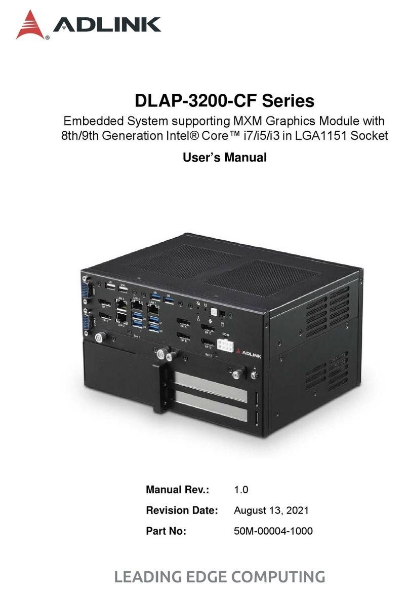
ADLINK Technology DLAP-3200-CF Series User manual

ADLINK Technology
ADLINK Technology DLAP-4000 Series User manual
ADLINK Technology
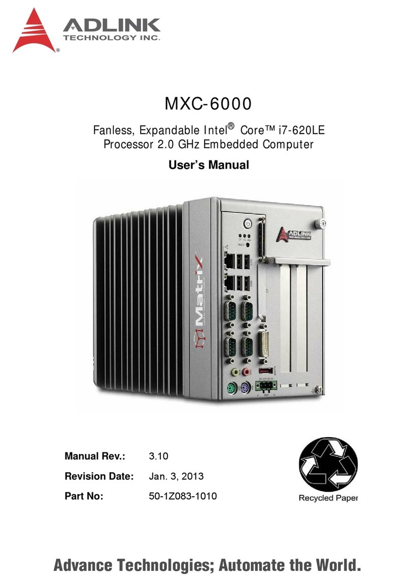
ADLINK Technology MXC-6000 User manual

ADLINK Technology
ADLINK Technology TALOS-3012 User manual

ADLINK Technology
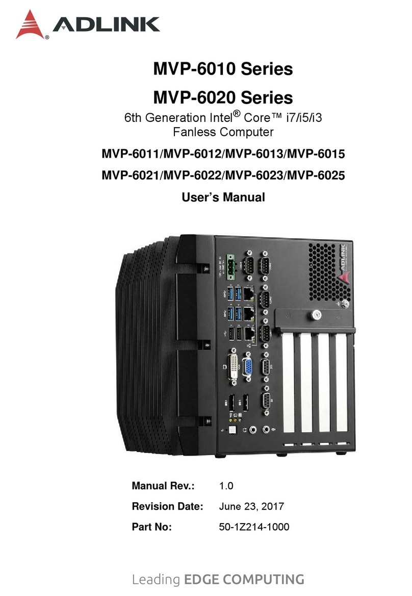
ADLINK Technology MVP-6010 Series User manual
ADLINK Technology
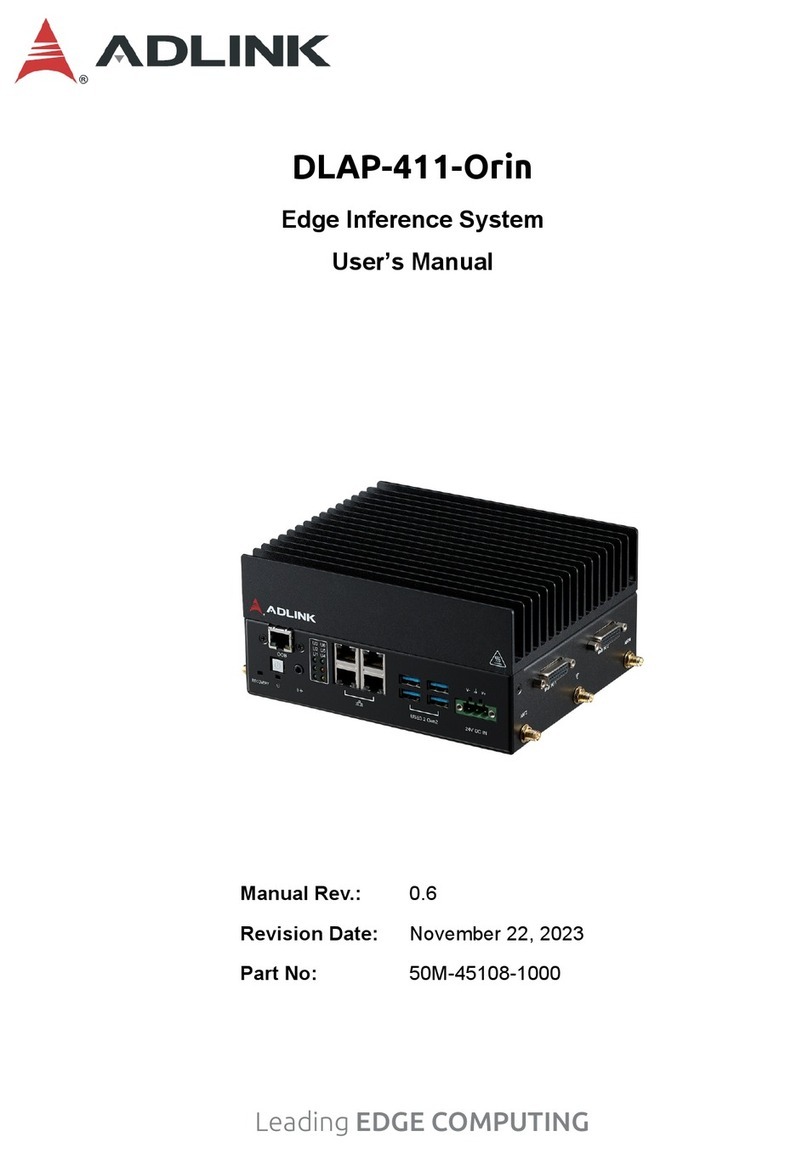
ADLINK Technology DLAP-411-Orin User manual