manuals.online logo
Brands
  1. Home
  2. •
  3. Brands
  4. •
  5. ADT
  6. •
  7. Control Panel
  8. •
  9. ADT Galaxy 8 Plus User manual

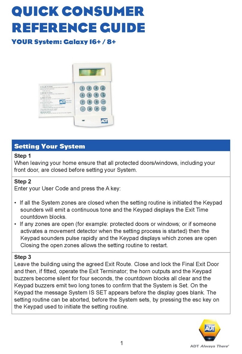
ADT Galaxy 8 Plus User manual

8 plus and16 plus
Users Guide
123
456
789
0
*#
ent
esc
A
u
B
u
GALAXY 16+ V2.XX
06.22 TUE 30 JUN
IU1-0018 ZST 962 Issue 2
iii
Contents
INTRODUCTION ......................................................................... 1
Glossary of Terms ..................................................................... 3
KEYPAD INFORMATION ........................................................... 5
Star (Ö) Key Features ............................................................................. 6
SETTING AND UNSETTING THE SYSTEM ............................... 7
SETTING THE SYSTEM.......................................................................... 7
UNSETTING THE SYSTEM .................................................................... 8
CANCELLING ALARMS .......................................................................... 8
USER MENU ............................................................................... 9
OPTION 1 – OMIT ................................................................................... 9
OPTION 2 – CHIME............................................................................... 10
OPTION 3 – WALK ................................................................................ 10
OPTION 4 – CODES..............................................................................11
OPTION 5 – TEST ................................................................................. 13
OPTION 9 – LOG................................................................................... 14
OPTION 10 – TIME................................................................................ 14
APPENDIX A — ALARM AND HELP MESSAGES ...................17
APPENDIX B – AVOIDING FALSE ALARMS ...........................19
ZONE REFERENCE TABLE......................................................21
ELBATECNEREFERENOZ
.oNepyTnoitacoLelbattimOtraP
10
20
30
40
50
60
70
80
90
01
11
21
31
41
51
61
21
INTRODUCTION
The Galaxy 8 plus and 16 plus V2 control panels used with your ADT Alarm
System are designed to the highest specifications and requirements using the
most advanced software and hardware technology.
The system is designed to satisfy the requirements of domestic and smaller
commercial installations, yet is flexible enough to provide ease of use and
operational versatility.
The system will normally consist of a boxed end-station, usually out of sight,
up to three remote LCD keypads, signalling equipment and a variety of
detectors.
The two line 16 character LCD keypads enable the user to Set and Unset the
system and operate the various available functions which are described in
this User’s Guide.
This User’s Guide contains the information required to operate the system, a
Glossary of Terms is given overleaf. An ADT Engineer will program and
commission the system to meet your requirements.
Thesystemissimpletooperate but usersareadvisedtoreadthis guide carefully
before using the system and retain it in a safe place for future reference.
1
19
APPENDIX B  AVOIDING
FALSE ALARMS
False alarms are inconvenient and may give rise to Police response being
withdrawn from your site which may affect your insurance cover.
Here are twelve points to help you avoid false alarms:
1. Ensure that you understand how to operate the alarm system. In your
absence the system should be operated by someone thoroughly
instructed in its use.
2. Ensure that:
• you know your User Code
• your Password is readily available if you need to quote it to the
Alarm Receiving Centre.
3. Before leaving the premises ensure that all doors and windows are
securely closed.
4. Ensure that detection devises such as Infra-red beams or movement
detectors are not obstructed by stock or building partitions.
5. Where Passive Infra-red (PIR) or movement detectors are installed
make sure that the area is kept free from animals and birds. Particular
attention should be paid to swinging signs, fluorescent lights and
Christmas decorations. Electric fans, heating or ventilation systems
should, where possible, be switched off before the system is Set.
6. Always follow the setting and unsetting procedure and keep to the
entry and exit routes agreed with ADT Security Systems.
7. Treat the alarm system with care and ensure that it is not accidentally
damaged.
8. ConsultADT SecuritySystems about alterations to your building and
itscontentsifyou think theymayaffectyour system oritsperformance.
9. Always report any obvious reasons for unwanted or false alarms to
ADT Security Systems. If necessary an engineer will be sent to check
the system where it is established that a technical fault exists.
10. If opening or closing times are monitored by the Alarm Receiving
Centre be sure you notify them of any changes from the agreed times
using your password where necessary.
11. While the system will be provided with a stand-by battery for use in
theeventof ana.c. mains failureevery effort shouldbe made torestore
the a.c. mains supply as soon as possible.
12. Make sure that regular maintenance checks are carried on the system
to minimise the risk of technically related false alarms.
GLOSSARY OF TERMS
Chime: Programming method which enables an internal audi-
ble warning following the operation of a detector or
contact.
Duress: Applicable when a remote signalling device is
fitted. A Duress code entered at the keypad will
Unset the system but transmit a Duress code to the
Alarm Receiving Centre.
Entry Time: Apresettimedelay to allowtheuserto reach thekeypad
and Unset the system.
Exit Time: A preset time delay to allow the user to leave the
building during setting the system.
ExitTerminator: A switch or push-button located on the outside of the
premisesandused to Setthe system. Thisis also known
as a Final Set button.
Event Log: The control panel memory which stores, in
sequence, a record of the system events.
Final Exit: The last door closed or detector operated by the
user on exit.
LCD Liquid Crystal Display.
Non–omit: An alarm circuit which cannot be omitted by the user.
Numeric Keypad: The partof theoperator panel comprisingnumber keys
Omit: Intentionally setting with alarm zones excluded
from the system. Only zones programmed as
“omit-enable” by the engineer can be omitted.
PA Panic Alarm: an emergency button or switch used to
set off the alarm; results in instantaneous
transmission of a silent alarm signal using the
remote signalling device.
Part Set: To set only part of the system.
Programme: To select the system functions or options.
Remote Signalling
Device: A optional signalling device connecting the alarm
system to an Alarm Receiving Centre via the
telephone line.
Set: To arm the system.
Unset: To disarm the system.
3
UserCode: A four digit code that has been programmed to be
accepted by the system.
Walk Test: A routine test of the alarm detectors.
24 Hour Circuit: An alarm circuit which has been programmed to be
armed continuously whether the system is Set or
Unset.
417
APPENDIX A  ALARM
AND HELP MESSAGES
ALARM IS ACTIVE: The system is currently in alarm and must be can-
celled by a valid User Code.
PA RESET REQUIRED: The User Code that cancelled the alarm does not
have the authorisation to reset the system. A User Code with the PA Reset
attribute enabled must be entered. The PA switch which created the alarm
may also have to be reset.
ENGINEER RESET REQUIRED: This message is displayed when a tamper
alarm occurs. Tamper alarms usually require an engineer to visit the site and
check all modules on the system.
INVALID CODE: The code that was entered is not registered in the system
memory.
DUPLICATED CODE: When assigning new User Codes, the code entered
has already been assigned to a code.
TIMED TIMEOUT DISABLED: When setting the system, the Exit Time has
been set to infinity and a Final zone or Push-to-Set zone is used to act as the
exit terminator.
TELECOM FAILURE:A faulthas occurred with the telephone line or remote
signalling which will require engineer attention.
KEYPAD INFORMATION
The Galaxy system is programmed and operated from the LCD keypads.
Figure 1 Galaxy Mk 3 LCD Keypad.
Number Keys (0–9): are used to enter your User Code and to select and
modify options.
View (Aand B) Keys: are used to Set the system and to step through the
menu options during programming.
Enter (ent) Key: The ent key allows you to Unset the system, to access the
menu options and to accept programming selections.
Escape (esc) Key: The esc key permits you to cancel any modifications
made to a menu option and allows you to return to the previous menu option
level. The esc key also aborts the setting routine if pressed during the Exit–
Time from the same keypad used to initiate the setting.
Hash (#) Key: The #key is used as a toggle key, which enables or disables
theprogramming features of certain menu options. It is also used to select the
user attributes feature in menu option 4 – Codes.
Star (Ö)Key: The Ökey, when combined with other keys, provides special
functions. The engineer will advise of these where applicable, see also: Star
(Ö) Key Features.
5
2 × 16 CHARACTER
LCD DISPLAY
123
456
789
0
ent
esc
*
#
A
u
B
u
GALAXY 16+ V2.XX
06.22 TUE 30 JUN
POWER LED
Power LED:The green power LED remains lit whenever the system is con-
nected to the a.c. mains power supply and a charged stand-by battery. A
mains power failure is indicated by the LED flashing slowly. A fuse or bat-
tery failure is indicated by the LED flashing quickly.
Note: A fuse or battery failure will require an Engineer Reset after the fault
has been corrected.
Your User Code: is a four digit personal identification number which iden-
tifies you and allows you to operate the system.
Note: Entry of an invalid code will cause the keypad to display the message
INVALID CODE. Entry of six consecutive invalid codes will cause a
tenminutekeypad lockout duringwhich the keypadhornswill activate
and the keypad will display the message ALARM IS ACTIVE. No
further code entries will be recognised during the lockout period.
Star Key (Ö) Features
Thestar keyis usedas a shift key; when combined with other keys it provides
additional system features. The Star Key features are only available if they
have been enabled. The Star Key features can only be enabled/disabled by
the ADT alarm engineer. Table 1 gives the key combinations for the Star key
features.
The ADT alarm engineer will advise you of the operation of these features
where appropriate.
6
noitanibmoCyeKerutaeFratS
Ö1emulovrezzubdapyeksegnahC .ffOdnawoL,hgiHneewteb
Ö2.mralaAPsetavitcA
Ö4.ffO/nOgnithgilkcabdapyekselggoT
Ö5mralAtsissAsetavitcA
sserpnehtedocretnE Ö6.sliatedmetsyseritneehtstnirP
sserpnehtedocretnE Ö7.goLtnevEeritneehtstnirP
Ö8.mralAeriFsetavitcA
Table 1: Star Key Features.
Note: A printer must be fitted to the system for the print options to work.
15
Selecting the Time Option
Enterthe ManagerCode andpress theentkey. Press theBkey untilthe Time
option is displayed then press the ent key.
Operation of the Time Option
On selecting the Time option 1=TIME is displayed. If the time requires to be
modified press the ent key and enter the time (this is a four digit number and
must be a valid time between 00:00 and 23:59). Press the ent key to accept
the programming and esc to cancel.
To change one of the other time features use the Aor Bkeys to select the
required option and follow the same procedure.
To exit from the Time option press the esc key.
Setting and Unsetting the System
Setting the System
Before Setting the System
Before the setting of a system is initiated ensure that:
• All doors and windows are secured.
• All areas protected by movement detectors are free from obstructions
and any animals are excluded from the areas to be protected.
Full Setting the System
Enter your User Code and press the Akey:
• If all the system zones are closed when the setting routine is initiated
the keypad sounders will emit a continuous tone and the keypad
displaysthe Exit Time countdown blocks(If optionedfor timedexit) .
• If any zones are open (for example: protected doors or windows; or if
someone activates a movement detector, when the setting process is
started) then the keypad sounders will pulse rapidly and the keypad
will display which zones are open. Closing the open zones will allow
the setting routine to restart.
Leave the building using the agreed exit route. Close and lock the Final Exit
Door and then operate the Exit Terminator; the horn outputs and the keypad
buzzers become silent , the countdown blocks all clear and four seconds later
the keypad buzzers emit two long tones to confirm that the system is Set. On
the keypad the message SYSTEM IS SET briefly appears before the dis-
play goes blank.
The setting routine can be aborted, before the system sets, by pressing the
esc key on the keypad used to initiate the setting routine.
Part Setting the System
Your alarm system can be Part Set using the B key. To Part Set the system
enter your User Code then press the Bkey. The keypad will then display the
Set/Unset status of those parts assigned to your code.
Leavethe building using the agreed Exit Route.Close and lock the Final Exit
Door and then operate the Exit Terminator; the horn outputs and the keypad
buzzers become silent , the countdown blocks all clear and four seconds later
the keypad buzzers emit two long tones to confirm that the system is Set. On
the keypad the message SYSTEM IS SET briefly appears before the
display goes blank.
The setting routine can be aborted, before the system sets, by pressing the
esc key on the keypad used to initiate the setting routine.
Note: Ifthe Silent PartSet facility hasbeen enabled onlythe keypad display
willindicatethe settingstatus, that is, no audibletones will beemitted.
7
Figure 3 Viewing the Event Log.
The log event displays the event type, time, descriptor and number. Also
displayed is the activation (+) and deactivation (–) signaller.
Thehighest event number (maximum of 250 events) isthe most recent event.
To display the date of the event currently being displayed press the #key.
Repressing the #key will return the display to the event details.
To quickly move through the log enter a three digit number between 001 and
250 followed by the #key. The system will jump to the event number en-
tered.
To escape from the Log option press the esc key.
Option 10  Time
The Time option allows the system manager (User 14) to modify the four
time features of the system, these are:
• Time (hr:min)
• Date (dd/mm/yy)
• Start Summer (dd/mm) – the date that summer time begins
(clocks go forwards).
• End Summer (dd/mm) – the date that summer time ends (clocks
go backwards).
14
Option 9  Log
The Log option permits the system manager (User 14) to view the events
stored in the system log.
Selecting the Log Option
Enter the Manager Code and press the 9key.
The Event Log
Once the Log option has been selected the current date is displayed. To view
the Event Log press the Aor Bkey to move through the log. Figure 3 shows
the Event Log display.
09:57STAR KEY+
TENABLE 092
Event time
Event type Event
activation/deactivation
signaller
Event descriptor
Event number
8
Unsetting the System
NormalEntry
The system begins the unsetting routine whenever a Final door is opened or
anExit/Entry zoneis activated (If Part Set). The keypadbuzzers pulseslowly
indicating that the Entry Time countdown has started.
To Unset the system, go directly to the keypad using the agreed entry route,
enter your code and press the ent key.
Slow Entry
The keypad sounder begins to pulse rapidly after 75% of the Entry Time has
expired to indicate that time is running short. If the Entry Time expires be-
fore a valid User Code is entered, a full alarm occurs.
Straying From The Entry Route
If,during the entry routine, you stray from the agreed entry routeand activate
a zone in a protected area an audible alarm occurs.
Alarm Abort
Notes: If the system is programmed for Alarm Abort a period of 90 seconds
after expiry of the Entry Time is provided to enable the user to cancel
an alarm caused by exceeding the Entry Time or deviating from the
entry route.
If the 90 second Alarm Abort time is exceeded then a full alarm may
resultinthePolicebeing called to thepremisesandthe system requiring
an Engineer Reset.
Cancelling Alarms
To cancel an alarm enter your User Code. The keypad displays the zones that
have been activated during the alarm. Press the esc key to return to the nor-
mal display.
Certain types of alarms, once cancelled, require a code authorised with the
appropriate reset authorisation to be entered. The system prompts for a valid
resetcodeby displayingINTRUDER RESET REQUIRED,PA RESET REQUIRED
or ENGINEER RESET REQUIRED on the keypad.
Engineer Reset
Certain types of alarm require an engineer to visit the site and, after investi-
gation, reset the system.
13
When the Codes option is selected User 01 is displayed. Press the ent key to
select this user or the Aor B key to view the other users. To modify the
attributes of the selected user press the #key.
The Set Access attribute is displayed along with its status. Press the #key to
toggle the enable status of the attribute. An attribute is enabled when the
square next to the attribute number is black and Enable appears on the bot-
tom line of the display.When the required attributes have been assigned to
the user, press the ent key to save the selection. The display returns to the
selected user number. Press the Aor Bkey to view and select other users.
To exit from the codes option press the esc key.
Note: TheManager Code can always modifythe attributes of the otherUser
Codes. The Manager Code can be used to enable the Modify Codes
option on other User Codes allowing these codes to modify other
code’s attributes.
Keyswitch Zones and User Codes
Keyswitches are assigned the attributes of User Code 1, 2 or 3. A Keyswitch
zone assigned to one of these codes can Set and Unset the parts assigned to
the code and reset authorised alarms. The user code assigned to the Keys-
witchmust be assigned Set Access to allow the Keyswitchto setthe allocated
parts.The Keyswitch assumesthe assigned attributeseven if thecode has not
been allocated a PIN.
Your engineer will advise you of the use of Keyswitch zones where neces-
sary.
Option 5  Test
The Test option allows the Manager Code (User 14) to test the Bells and
Strobe outputs on the system.
Selecting the Test Option
Enter the Manager Code and press the 5key.
Operation of the Test Option
On selecting the Test option 5BELLS is displayed. If the bells are to be
tested press the #key. Any output programmed as Bells will activate. To end
the test repress the # key.
Pressing the Akey will display 6STROBE (whereapplicable). If the strobes
are to be tested press the #key. To end the test repress the #key.
To exit from the Test option press the esc key.
9
User Menu
For access to the menu options key in your User Code then press the entkey.
The keypad then displays the menu options available to the user.
noitpOuneM
oNnoitpO
10timO
20emihC
30klaW
40sedoC
50tseT
90goL
01emiT
Table 2 Menu Options.
The user menu offers a selection of up to seven options. All users have
access to the Chime, Omit and Walk options. The Code options are assigned
to users, (if required) by the installer.
The system manager (User 14) can also:
•Test outputs (Bells and Strobe only).
•ViewtheEvent Log.
•Modify the Time options.
Note: The keypad returns to the normal display if no key press occurs for
two minutes while accessing the menu.
The menu options are described in the following pages.
Option 1  Omit
This option allows authorised users to omit designated zones from the sys-
tem.Once a zonehas been omittedit isnot able togenerate an alarmcondition
when the system is set. Omitted zones are reinstated automatically when the
system is Unset or manually when the Omit feature is disabled by the user.
Selectingthe OmitOption
Enter your user code and press the ent key to select the menu options. Press
the ent key again to select Omit.
oNetubirttAnoitpircseD
10sseccAteSriehtgniretneybmesysehtteSotresuehtselbanE .yekAehtgnisserpdnaedoc
20sseccAtesnUgniretneybmetsysehttesnUotresuehtselbanE .yektneehtgnisserpdnaedocrieht
30sseccA1traP.1traPotsseccaresuehtseviG
40sseccA2traP.2traPotsseccaresuehtseviG
50sseccA3traP.3traPotsseccaresuehtseviG
60gnittimO.senozelbattimotimootresuselbanE
70sedocyfidoM.setubirttadnasedoCresUmargorpotresuselbanE
Table 4 User Code Attributes.
01=USR 1 CODE z
ENT,01-14=SELECT
User Number
Option Selections
User Code
Assigned Indicat
o
Selecting the Codes option
Enter your User Code and press the 4key.
Assigning Modifying and Deleting User Codes
Once the Codes option is selected the User Code assignment of User 1 is
displayed. If the box next to CODE is filled then a PIN has been assigned, if it
is blank then no PIN has been assigned. Use the Aor Bkeys to select a user
number and press the ent key.
Figure 2 Menu Option 4 – Codes.
To assign or modify a user PIN enter a four digit number. Press the Ökey to
erase any digits incorrectly entered. When the required four digit code is
displayed press the ent key.
If a User Code is to be deleted press the Ökey four times followed by the ent
key.
Note: User Code 13 may be assigned as a Duress Code. Entry of this code
causes a Duress alarm which will activate the PA outputs and trigger
the Remote signalling Device (if fitted); the Horn, Bells and Strobe
outputsdonotactivate. Yourengineerwill advise youon the operation
of this function where applicable.
Assigning User Attributes
12
10
Omitting Zones
When the Omit option is selected, zone 01 is displayed, along with its omit
eligibility and status (NON OMITTABLE– the zone cannot be omitted; #,01
OMIT – the zone is omittable; OMIT – the zone is currently omitted).
If the zone is currently omitted then the box on the top line of the display will
be filled; if zone is not currently omitted then the box is empty.
If the zone can be omitted and the omit status is to be changed, press the #
key. The display indicates the new omit status of the zone. Use the Aor B
keys to view and select other zones.
Setting with Omitted Zones
Once the required zones have been selected for omission press the ent key.
The system begins to set omitting the selected zones. To abort the setting
routine press the esc key. The selected zones remain omitted allowing the
system to be set, as normal, at a later time.
To set the system after zones have been omitted initiate the Full or Part Set-
ting routine. The system starts to set and the keypad display indicates how
many zones have been omitted. The zones will remain omitted until the sys-
tem is Unset.
Option 2  Chime
This option allows the user to assign the Chime function to the zones on the
system. Any zone with the Chime function enabled momentarily activates
the keypad buzzers each time the zone is opened.
Selecting the Chime Option
Enter your User Code and press the 2key.
Onselecting the Chime option the first zoneis displayed along with its chime
status (enabled or disabled). Pressing the #key changes the chime status of
the zone.
Press the Aor Bkeys to view and program the other zones on the system.
Press the ent key to accept the programming or esc to cancel.
Option 3  Walk
The Walk option allows the user to Walk test the zones on the system, ensur-
ing that they are operating correctly.
Selecting the Walk Option
Enter your User Code and press the 3key.
11
On selecting the Walk option zone 01 is displayed. If the zone is to be tested
pressthe #key.Use theAor Bkeysto scrollthrough the zones on the system,
each one may be selected for inclusion in the test. When all the required
zoneshave been selected press the entkey tostart theWalk Test. The keypad
displays the number of Walk Test zones currently open on the system. Press-
ing the Aor Bkeys allows the currently open zones to be viewed.
Walk test the selected zones by activating the appropriate sensor (movement
detector, door contact, etc). When the Walk Test is complete return to the
keypad. The display shows the number of test zones that are currently open.
Press the #key to toggle the keypad display between showing the number of
test zones currently open and the number of zones registered as tested.
To terminate the Walk Test press the esc key.
Note: If the esc key is not pressed the Walk Test will remain active for
20 minutes after the last key press.
Option 4  Codes
The Codes option enables authorised users to allocate, modify and delete
User Codes (PINs), as well as assign and modify user attributes. Only users
with the Modify Codes attribute (option 7, see Table 4) enabled can carry out
these functions.
Note: TheGalaxy8 plus hassix user codes(Users one tofour, (Duresscode)
user thirteen and (Manager Code) user fourteen) and one Engineer
Code(User15). TheGalaxy16 plus has fourteen usercodes(users one
to thirteen and (Manager Code) fourteen) and one Engineer Code.
Thisis summarised inTable 3.
edoCresU8yxalaG
sulp
61yxalaG
sulp
10 üü
20 üü
30 üü
40 üü
50 ûü
60 ûü
70 ûü
80 ûü
90 ûü
01 ûü
11 ûü
21 ûü
)sseruD(31 üü
)rgM(41 üü
)gnE(51 üü
Table 3 User Codes for Galaxy 8 plus and 16 plus.

This manual suits for next models

1

Other ADT Control Panel manuals

ADT Unimode 400 Multi-Net User manual

ADT

ADT Unimode 400 Multi-Net User manual

ADT Command Hybrid User manual

ADT

ADT Command Hybrid User manual

ADT PM33 User manual

ADT

ADT PM33 User manual

ADT Home Assure User manual

ADT

ADT Home Assure User manual

ADT SafeWatch 3000 Use and care manual

ADT

ADT SafeWatch 3000 Use and care manual

ADT Unimode 9600 User guide

ADT

ADT Unimode 9600 User guide

ADT Galaxy 16 Plus User manual

ADT

ADT Galaxy 16 Plus User manual

ADT Ademco Vista 10P User manual

ADT

ADT Ademco Vista 10P User manual

ADT ADT-LCD40 User manual

ADT

ADT ADT-LCD40 User manual

ADT 6128B User manual

ADT

ADT 6128B User manual

ADT Honeywell Domonial User manual

ADT

ADT Honeywell Domonial User manual

ADT 2 Gig Go! Control User manual

ADT

ADT 2 Gig Go! Control User manual

ADT DSC 1832 User manual

ADT

ADT DSC 1832 User manual

ADT DSC Power Series User manual

ADT

ADT DSC Power Series User manual

Popular Control Panel manuals by other brands

Sargent Cameo AC80 quick start guide

Sargent

Sargent Cameo AC80 quick start guide

DeDietrich IniControl 2 Troubleshooting

DeDietrich

DeDietrich IniControl 2 Troubleshooting

FAAC 455 D Supplemental installation instructions

FAAC

FAAC 455 D Supplemental installation instructions

Rehau NEA operating instructions

Rehau

Rehau NEA operating instructions

Truma CP plus Operating and installation instructions

Truma

Truma CP plus Operating and installation instructions

Seada SDCP9 Series user manual

Seada

Seada SDCP9 Series user manual

Pro-tec 3500 Installation and commissioning manual

Pro-tec

Pro-tec 3500 Installation and commissioning manual

Security Command XR6 user guide

Security Command

Security Command XR6 user guide

Spraying Systems AutoJet 2850+ owner's manual

Spraying Systems

Spraying Systems AutoJet 2850+ owner's manual

wattstopper LC8-120/277 user manual

wattstopper

wattstopper LC8-120/277 user manual

HIK VISION DS-PK00 series user manual

HIK VISION

HIK VISION DS-PK00 series user manual

SIGMA TEK HBG 1011 manual

SIGMA TEK

SIGMA TEK HBG 1011 manual

Entrematic Ditec EL31R installation manual

Entrematic

Entrematic Ditec EL31R installation manual

Black Box C6AMP70-24 manual

Black Box

Black Box C6AMP70-24 manual

Clear-Com 4000 series II Technical manual

Clear-Com

Clear-Com 4000 series II Technical manual

HIK VISION DS-PK-LRT(433MHz) user manual

HIK VISION

HIK VISION DS-PK-LRT(433MHz) user manual

G-Force UNDER CONTROL SP-35 user manual

G-Force

G-Force UNDER CONTROL SP-35 user manual

mr. steam SMART/TWO Installation & operation instructions

mr. steam

mr. steam SMART/TWO Installation & operation instructions

manuals.online logo
manuals.online logoBrands
  • About & Mission
  • Contact us
  • Privacy Policy
  • Terms and Conditions

Copyright 2025 Manuals.Online. All Rights Reserved.