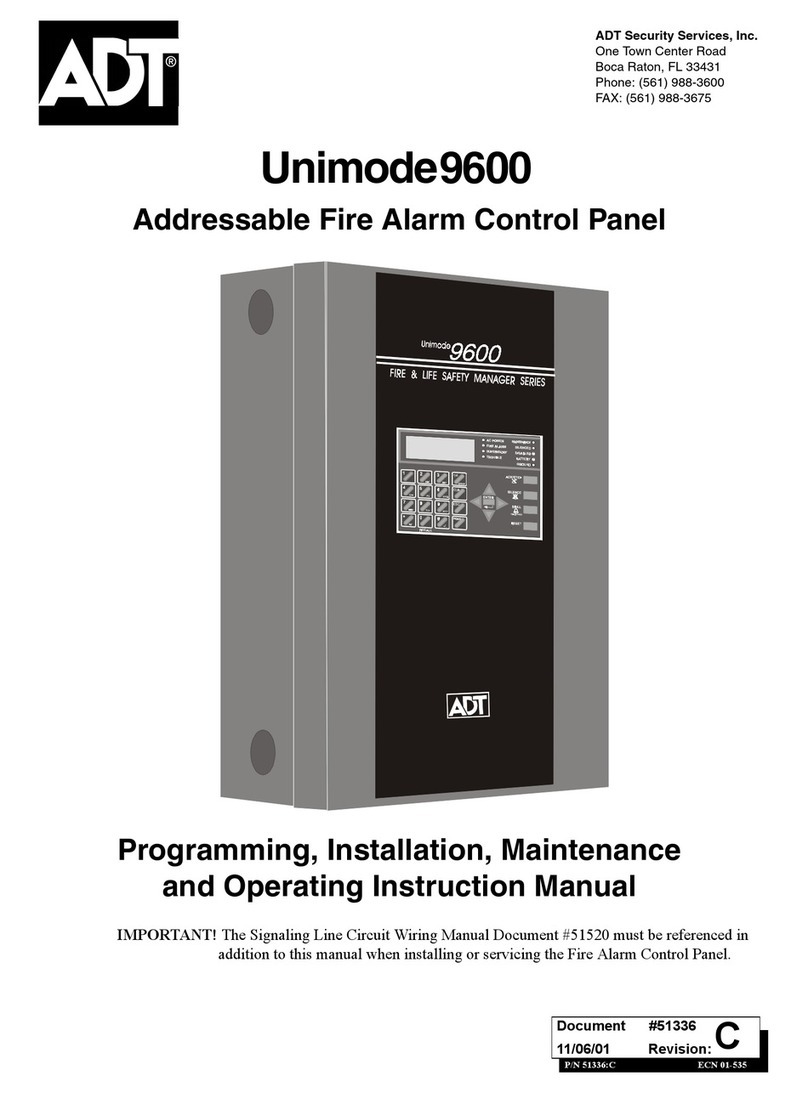
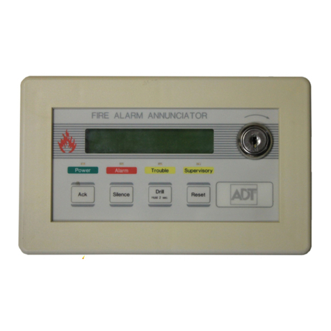
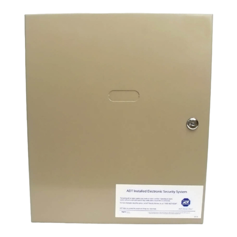
ADT Unimode 400 Multi-Net User manual

8QLPRGH0XOWL1HW
$QDORJ)LUH3DQHO
Installation Manual
'RFXPHQW
5HYLVLRQ A
31 $ (&1
ADT Security Services, Inc.
1750 Clint Moore Road
Boca Raton, FL 33431
(561) 988-3600


Unimode 400 Installation PN 50710:A 10/22/97 iii
7DEOHRI&RQWHQWV
6\VWHP2YHUYLHZ Introduction ..............................................................................................................1-1
About this Manual..................................................................................................1-1
Description.............................................................................................................1-1
Standard Features and Options...............................................................................1-2
System Limitations.................................................................................................1-2
System Diagram.....................................................................................................1-3
Specifications.............................................................................................................1-4
Overview................................................................................................................1-4
AC Power...............................................................................................................1-4
Battery (sealed lead-acid only)...............................................................................1-4
Signaling Line Circuit (SLC) Loop........................................................................1-4
Notification Appliance and Releasing Circuits
(MPS-400 ICM-4, ICE-4) ..........................................................................................1-5
Relays.....................................................................................................................1-5
Four-wire Smoke Detector Power..........................................................................1-5
Power Outputs........................................................................................................1-6
Operating Power.....................................................................................................1-6
AC Branch Circuit .............................................................................................1-6
Secondary Power Source (Batteries) .................................................................1-6
System Components .................................................................................................1-7
Basic Equipment Packages ....................................................................................1-7
ADT-CPU ..............................................................................................................1-7
Power Supplies.......................................................................................................1-8
Audio Amplifiers ...................................................................................................1-9
Transformer Assembly and MPS-400PCA............................................................1-9
Battery Boxes.........................................................................................................1-9
Optional Devices.....................................................................................................1-10
Intelligent Detectors ...............................................................................................1-11
Overview..............................................................................................................1-11
Detector Descriptions...........................................................................................1-11
Addressable Modules .............................................................................................1-12
Overview..............................................................................................................1-12
Module Descriptions............................................................................................1-12
End-of-Line Devices ...............................................................................................1-13
Annunciation Modules...........................................................................................1-14
Overview..............................................................................................................1-14
ADT-LDM Series Lamp Driver Modules............................................................1-14
Annunciator Control System (ACS) ....................................................................1-15
Annunciator Fixed Modules.................................................................................1-15
Peripheral Displays and Printers..........................................................................1-16
Overview..............................................................................................................1-16
ADT-LCD-80 Display .........................................................................................1-16
PRN-4 Remote Printer .........................................................................................1-16
Keltron Remote Printer (Model VS4095)............................................................1-16
CRT-2 Terminal...................................................................................................1-16
Notification Circuit and Control Modules ...........................................................1-17
Overview..............................................................................................................1-17
Descriptions of Modules ......................................................................................1-17
Voice Alarm Equipment ........................................................................................1-18
Overview..............................................................................................................1-18
Audio Message Generator (AMG-1) ...................................................................1-18

7DEOH RI &RQWHQWV
2. Installation
iv Unimode 400 Installation PN 50710:A 10/2297
Audio Tone Generator (ATG-2) ..........................................................................1-18
Fire Fighters Telephone FFT-7/FFT-7S...............................................................1-18
Voice Control Module (VCM-4) .........................................................................1-18
Dual Channel Module (DCM-4)..........................................................................1-18
Cabinet Hardware..................................................................................................1-19
Cabinet Overview.................................................................................................1-19
CHS-4M Chassis/Dress Panel Assembly.............................................................1-19
CHS-4L Chassis...................................................................................................1-19
ADT-CAB-X3 Series Cabinets............................................................................1-20
Overview..........................................................................................................1-20
ADT-CAB-A3 .................................................................................................1-20
ADT-CAB-B3..................................................................................................1-20
ADT-CAB-C3..................................................................................................1-21
ADT-CAB-D3 .................................................................................................1-21
ADT-CAB-400AA Cabinets................................................................................1-22
ADT-CAB-400AA Overview..........................................................................1-22
ADT-CAB-400AA Limitations.......................................................................1-22
ADT-CAB-400AA Dimensions ......................................................................1-22
,QVWDOODWLRQ Preparing for Installation........................................................................................2-1
Installation Checklist................................................................................................2-2
Installing a Cabinet Door
Cabinet Door Mounting Guidelines.......................................................................2-4
How to Install a Cabinet Door (ADT-CAB-X3 only)............................................2-4
Installing the Door Alignment Tabs.......................................................................2-5
Installing a Chassis (ADT-CAB-X3 Series Cabinets)
Overview................................................................................................................2-6
Installing a CHS-4 Chassis.....................................................................................2-6
Installing a CHS-4L Chassis..................................................................................2-6
Mounting a Backbox (SBB-X3 and ADT-CAB-400AA).......................................2-7
Mounting an MPS-400 Power Supply
Mounting an MPS-400 into an ADT-CAB-X3 Cabinet ........................................2-8
Mounting an MPS-400 into an ADT-CAB-400AA...............................................2-9
Mounting an Optional AVPS-24 Power Supply
Overview..............................................................................................................2-10
Installation............................................................................................................2-10
Installing an Auxiliary Relay Module (ARM-4)
Overview..............................................................................................................2-11
Mounting the ARM-4 Module to a CHS-4 Chassis.............................................2-11
Wiring the ARM-4 Module..................................................................................2-12
Connecting the MPS-400 Power Cables
MPS-400 Electrical Connections .........................................................................2-13
Connecting the MPS-400 to AC Power (TB1) ....................................................2-13
Connecting the Batteries (MPS-400, TB1-6, TB1-7) ..........................................2-13
Connecting Four-Wire Smoke Detector 24 VDC Power (MPS-400, TB2).....2-14
Notification Appliance Power (24 VDC) ........................................................2-14
Annunciator Power (24 VDC).........................................................................2-14
System Harness Connections...........................................................................2-14
System Power Connections .............................................................................2-14
Installing Expander Row Ribbon Cables for Panel Modules
Installing Row Ribbon Cables for ADT-CAB-B3 – ADT-CAB-D3 Cabinets....2-15
Installing Row Ribbon Cables for ADT-CAB-C3 and ADT-CAB-D3 Cabinets 2-16
Installing Row Ribbon Cables for an ADT-CAB-400AA Cabinet......................2-17
Installing the CPU
Installing the CPU into a Chassis.........................................................................2-18

2. Installation
7DEOH RI &RQWHQWV
Unimode 400 Installation PN 50710:A 10/22/97 v
Connecting the CPU to the MPS-400 ..................................................................2-19
Mounting Expander Modules (CRE-4, ICE-4, VCE-4)......................................2-20
Mounting Panel Modules (CRM-4, ICM-4, VCM-4) onto a Chassis................2-21
Installing a 4XTM Module (Remote Station Fire Alarm)
Mounting the Module...........................................................................................2-22
4XTM Electrical Requirements ...........................................................................2-22
Connecting the 4XTM Module............................................................................2-23
Installing an ADT-UZC-256 Module
Overview..........................................................................................................2-24
ADT-CAB-X3 Installation ..............................................................................2-24
ADT-CAB-400AA Installation........................................................................2-24
Field-Wiring the Modules
Notification Appliance Circuit (NAC) Wiring ....................................................2-25
MPS-400/ICM-4 NAC Configurations................................................................2-25
Typical Power Supply/Notification Appliance Circuit Configurations...........2-25
AVPS-24/ICM-4 NAC Configurations ..........................................................2-26
Field-Wiring an ICM-4 and an ICE-4 (NFPA Style Y and Z).............................2-27
Field-Wiring a CRM-4 and the CRE-4................................................................2-28
CRM-4 and CRE-4 Wiring Guidelines............................................................2-28
CRM-4 and CRE-4 Connections .....................................................................2-28
Field Wiring an Optional AVPS-24 Power Supply .............................................2-29
AVPS-24 Wiring Overview.............................................................................2-29
AVPS-24 Wiring Diagrams.............................................................................2-29
Field Wiring Four-Wire Smoke Detectors (Style B and Style D) .......................2-30
Field Wiring Overview....................................................................................2-30
Field Wiring (Style D).....................................................................................2-30
Field Wiring (Style B) .....................................................................................2-30
Field Wiring the Auxiliary Relay Module (ARM-4) ...........................................2-31
Overview..........................................................................................................2-31
ARM-4 Terminal Assignments........................................................................2-31
Field Wiring the MPS-400 Power Supply ...........................................................2-32
MPS-400 Board ...............................................................................................2-32
DC Power Output Connections (MPS-400).....................................................2-33
AC and Battery Power Connections (MPS-400).............................................2-33
Wiring MPS-400 Output Circuits....................................................................2-34
Installing Remote Printers and CRTs
Remote Printers....................................................................................................2-35
Setting PRN-4 Options.........................................................................................2-35
Installing a PRN-4 Remote Printer ..................................................................2-36
Installing a Keltron Printer ..............................................................................2-37
Setting up the Keltron Printer..........................................................................2-37
Installing a CRT-2................................................................................................2-38
Connecting Multiple Printers, CRTs, or CRT/PRN Combination.......................2-38
Wiring a Signaling Line Circuit (SLC)
Overview of SLC Wiring.....................................................................................2-39
SLC Devices.........................................................................................................2-40
Control Panel Capacity ........................................................................................2-40
SLC Performance.................................................................................................2-41
SLC Shield Termination ......................................................................................2-42
Wire Requirements for a Two-Wire SLC............................................................2-43
Measuring Loop Resistance for a Two-Wire SLC ..........................................2-43
Measuring Total Wire Length for a Two-wire SLC........................................2-43
Wire Requirements for a Four-Wire SLC............................................................2-45
Measuring Loop Resistance for a Four-Wire SLC..........................................2-45
Measuring Total Wire Length for a Four-wire SLC........................................2-45
Style 6 Wiring Overview.................................................................................2-46
7DEOH RI &RQWHQWV
3. Testing the System
vi Unimode 400 Installation PN 50710:A 10/2297
Style 6 Wiring Diagram...................................................................................2-46

Style 7 Wiring Overview.................................................................................2-47
Style 7 Wiring Diagram...................................................................................2-47
Wiring an Isolator Module (M500X)...................................................................2-48
M500X Overview ............................................................................................2-48
Isolating a Branch of a Two-Wire SLC...........................................................2-48
Wiring an IDC with M500M Modules.................................................................2-49
Overview of Monitor Modules (M500M Series).............................................2-49
Wiring an M500M Module..............................................................................2-49
Wiring an NFPA Style B IDC with M500Ms.................................................2-50
Wiring an NFPA Style B IDC with M502Ms.................................................2-51
Wiring an NFPA Style B IDC with M500Ms................................................2-52
Wiring a NFPA Style D IDC with M502M Modules......................................2-53
Wiring a Notification Appliance Circuit (NAC) or Control Circuit....................2-54
M500CH Module Overview............................................................................2-54
Testing an M500CH Module...........................................................................2-54
Installing an M500CH as a Form-C Relay ......................................................2-55
SLC Wiring with M500CH Modules...................................................................2-55
Style Y NAC Circuits (Two-Wire)..................................................................2-56
Wiring Diagram and Instructions.....................................................................2-56
Style Z NAC ....................................................................................................2-57
Style Z NAC Circuits (Method 1 – MPS-400 powers M500CH)....................2-58
Style Z NAC Circuits (Method 2 – MPS-400 powers M500CH)....................2-59
SLC Wiring with an Intelligent Detector.............................................................2-60
Overview for Wiring Intelligent Detectors......................................................2-60
Wiring a B501B Detector to an SLC Loop......................................................2-60
SLC Wiring with an ADT-BGX-101L Addressable Manual Pull Station...........2-61
ADT-BGX-101L Overview.............................................................................2-61
ADT-BGX-101L Wiring Connections ............................................................2-61
7HVWLQJWKH6\VWHP Acceptance Test........................................................................................................3-1
Periodic Testing and Service ...................................................................................3-1
Operational Checks..................................................................................................3-1
Test Modes
Walk Test Mode.....................................................................................................3-2
Live Test Mode ......................................................................................................3-3
Battery Checks and Maintenance...........................................................................3-4
9RLFH$ODUP6\VWHP Section Overview ......................................................................................................4-1
Installing an AMG
Configuring the AMG............................................................................................4-4
AMG-1 and AMG-E Tone/Message Selections (SW2=Off).................................4-5
AMG-1 and AMG-E Tone/Message Selections (SW2=On)..................................4-6
ATG-2 Terminal Connections................................................................................4-7
Installing a Fire Fighter’s Telephone (FFT-7 and FFT-7S)
Overview................................................................................................................4-8
Mounting an FFT-7/FFT-7S ..................................................................................4-8
Connecting an FFT-7/FFT-7S................................................................................4-9
Installing Audio Amplifiers (AA-30/AA-100/AA-120)
Installing an AA-30..............................................................................................4-10
Overview..........................................................................................................4-10
Mounting an AA-30.........................................................................................4-10
AA-30 Terminals and Connectors...................................................................4-11
Installing an AA-100/AA-120..............................................................................4-12
Overview..........................................................................................................4-12

4. Voice Alarm System
7DEOH RI &RQWHQWV
Unimode 400 Installation PN 50710:A 10/22/97 vii
Mounting an AA-100/AA-120.........................................................................4-12
AA-100/AA-120 Terminals and Connectors...................................................4-13
Installing a Backup Amplifier..............................................................................4-14
Overview..........................................................................................................4-14
Typical Installation Drawing ...........................................................................4-14
Voice Alarm Modules
Overview..............................................................................................................4-15
Module Descriptions............................................................................................4-15
Connecting VCM-4 Speaker Circuits ..................................................................4-16
Overview..........................................................................................................4-16
VCM-4 Speaker Wiring Diagram....................................................................4-16
Connecting VCM-4 Telephone Circuits ..............................................................4-17
Wiring Diagram...............................................................................................4-17
Setting the VCM-4 to Speaker or Telephone Mode ........................................4-18
Connecting a M500CH Module to Speaker Circuits.......................................4-18
Connecting Dual Channel Module Circuits.........................................................4-19
Wiring Notes....................................................................................................4-19
Wiring Diagram...............................................................................................4-19
Voice System Configurations
Voice Systems Wiring Overview.........................................................................4-20
Internal Power Distribution..................................................................................4-21
Wiring Diagram...............................................................................................4-21
Block Diagram.................................................................................................4-21
CPU EIA-485 Connections..................................................................................4-22
Wiring Diagram...............................................................................................4-22
Block Diagram.................................................................................................4-22
Wiring an Audio Signal without a Backup Amplifier .........................................4-23
Wiring Notes....................................................................................................4-23
Typical Wiring Diagram..................................................................................4-23
Block Diagram.................................................................................................4-23
Audio Signal Wiring Using a Backup Amplifier.................................................4-24
Wiring Notes....................................................................................................4-24
Wiring Diagram...............................................................................................4-24
Block Diagrams ...............................................................................................4-24
CPU Trouble Bus Connections............................................................................4-25
Wiring Notes....................................................................................................4-25
Wiring Diagram...............................................................................................4-25
Block Diagram.................................................................................................4-25
Wiring Speaker Circuits
Wiring Speaker Circuit Overview........................................................................4-26
30 Watt/Four and Eight Speaker Circuits ............................................................4-27
Wiring Notes....................................................................................................4-27
Wiring Four Speakers ......................................................................................4-27
Wiring Eight Speakers.....................................................................................4-27
120 Watt/Four and Eight Speaker Circuits ..........................................................4-28
Wiring Notes....................................................................................................4-28
Wiring Four Speakers ......................................................................................4-28
90 Watt/Eight Speaker Circuit Configuration......................................................4-29
Wiring Notes....................................................................................................4-29
Wiring Diagram...............................................................................................4-29
240 Watt/Eight Speaker Circuit ...........................................................................4-30
Wiring Notes....................................................................................................4-30
Wiring Diagram...............................................................................................4-30
180 Watt/Eight Speaker Circuit Configuration....................................................4-31
Wiring Notes....................................................................................................4-31

7DEOH RI &RQWHQWV
5. Applications
viii Unimode 400 Installation PN 50710:A 10/2297
Wiring Diagram...............................................................................................4-31
30 Watt Dual-Channel Configuration ..................................................................4-32
Wiring Notes....................................................................................................4-32
Wiring Diagram...............................................................................................4-32
120 Watt Dual-Channel Configuration (Four AA-30s).......................................4-33
Wiring Notes....................................................................................................4-33
Wiring Diagram...............................................................................................4-33
120 Watt Dual-Channel Configuration (Two AA-120s) .....................................4-34
Wiring Notes....................................................................................................4-34
Wiring Diagram...............................................................................................4-34
Voice Message Options (VROM and VRAM)
Overview of VROM and VRAM.........................................................................4-35
Installing VROM and VRAM..............................................................................4-35
ACT-1 Audio Coupling Transformer
ACT-1 Overview..................................................................................................4-36
Isolating Power Supplies......................................................................................4-36
ACT-1 Installation ...............................................................................................4-37
Installation Notes.............................................................................................4-37
Installation Diagram ........................................................................................4-37
Connecting the ACT-1.....................................................................................4-37
$SSOLFDWLRQV Applications Overview.............................................................................................5-1
Central or Remote Station Fire Alarm System (UDACT)
Installation..............................................................................................................5-2
Wiring Diagram .....................................................................................................5-2
Auxiliary Fire Alarm System
Overview................................................................................................................5-3
Wiring Diagram .....................................................................................................5-3
NFPA 72-1993 Remote Station Fire Alarm System
Overview................................................................................................................5-4
Wiring Diagram .....................................................................................................5-4
ADT Network Interface Board (ADT-NIB-96)
ADT-NIB-96 Overview .........................................................................................5-5
ADT-NIB-96 Assembly.........................................................................................5-5
ADT-NIB-96 SLC and EIA-485 Connections.......................................................5-6
Wiring Specifications.............................................................................................5-6
Using the XP Transponder with the Unimode 400
XP Transponder Overview.....................................................................................5-7
Wiring Diagram .....................................................................................................5-7
Combination Fire/Security Applications/Security Applications
Overview................................................................................................................5-8
General Operation..................................................................................................5-8
Installing a Security Tamper Switch......................................................................5-8
Installing a Security Tamper Switch into the ADT-CAB-400AA....................5-8
Installing a Security Tamper Switch into the ADT-CAB-X3............................5-9
Programming..........................................................................................................5-9
Wiring for Proprietary Security Alarm Applications...........................................5-10
Universal Zone Coder (ADT-UZC-256)
ADT-UZC-256 Description .................................................................................5-11
ADT-UZC-256 Connectors and Indicators..........................................................5-11
NAC and EIA-485 Power Connections ...............................................................5-12
ADT-UZC-256 Electrical Connections................................................................5-13
Wiring Diagram ...................................................................................................5-13
Wiring 12 Zone-Coded NACs .............................................................................5-14
Wiring 20 Zone-Coded NACs .............................................................................5-15

Appendix A: Annunciators
7DEOH RI &RQWHQWV
Unimode 400 Installation PN 50710:A 10/22/97 ix
Releasing Applications
Overview..............................................................................................................5-16
Programming Releasing Applications..................................................................5-16
Wiring for Releasing Applications.......................................................................5-16
Connecting a Releasing Device to the MPS-400 .................................................5-17
Overview..........................................................................................................5-17
Typical Connections ........................................................................................5-17
Connecting a Releasing Device to an ICM-4/ICE-4 Module ..............................5-18
Overview..........................................................................................................5-18
Typical Connections ........................................................................................5-18
Connecting a Releasing Device to an M500CH Module.....................................5-19
Overview..........................................................................................................5-19
Typical Connections ........................................................................................5-19
Connecting an N-ARA-10 Agent Release-Abort Station ....................................5-20
Overview..........................................................................................................5-20
Typical Connections ........................................................................................5-20
Installing a Combination Waterflow/Supervisory Valve Monitor.......................5-21
Overview..........................................................................................................5-21
Typical Connections ........................................................................................5-21
$SSHQGL[$$QQXQFLDWRUV
Overview...................................................................................................................A-1
Annunciator Interfaces
Terminal Mode (ADT-LCD-80) ...........................................................................A-1
ACS Mode.............................................................................................................A-1
Annunciator Selection Groups
Overview...............................................................................................................A-2
ACS Annunciator Selection Group 1....................................................................A-3
ACS Annunciator Selection Group 2....................................................................A-4
ACS Annunciator Selection Group 3....................................................................A-5
ACS Annunciator Selection Group 4....................................................................A-6
ACS Annunciator Selection Group 5....................................................................A-7
ACS Annunciator Selection Group 6....................................................................A-8
ACS Annunciator Selection Group 7....................................................................A-9
ACS Annunciator Selection Group 8..................................................................A-10
ACS Annunciator Selection Group 9..................................................................A-11
Connecting Annunciators
Overview.............................................................................................................A-12
ADT-LCD-80 Terminal Mode EIA-485 Connection (CPU, TB3).....................A-13
Connection Guidelines....................................................................................A-13
Connecting ADT-LCD-80s in Terminal Mode...............................................A-13
ADT-LCD-80 ACS Mode EIA-485 Connection (CPU, TB4)............................A-14
Connection Guidelines....................................................................................A-14
Connecting ADT-LCD-80s in ACS Mode .....................................................A-14
Powering ADT ACS-, LDM-, ACM-, and LCD-type Annunciators..................A-15
Overview.........................................................................................................A-15
Power Connections .........................................................................................A-15
Power Connections for ADT-LCD-80 Annunciators .....................................A-15
ADT-ACS and ADT-LDM Series EIA-485 Connection....................................A-16
Connection Guidelines....................................................................................A-16
EIA-485 Connections .....................................................................................A-16
$SSHQGL[%:LUH5HTXLUHPHQWV
$SSHQGL[&&RPSDWLEOH(TXLSPHQW

7DEOH RI &RQWHQWV
Appendix D: CRT-2 Configuration
xUnimode 400 Installation PN 50710:A 10/2297
$SSHQGL['&57&RQILJXUDWLRQ
Overview...............................................................................................................D-1
Setting CRT-2 Parameters.....................................................................................D-1
Uploading or Downloading the Operating Program.............................................D-2
$SSHQGL[(7HUPLQDO,QWHUIDFH3URWRFRO
General Description................................................................................................. E-1
Operating Modes
Local Terminal Mode (LocT) ............................................................................... E-1
Local Monitor Mode (LocM)............................................................................ E-2
Remote Terminal Mode (RemT) ...................................................................... E-3
Using the CRT-2 for Read Status
Overview............................................................................................................... E-4
Accessing Read Status Options............................................................................. E-4
Read Point............................................................................................................. E-5
Display Devices in Alarm or Trouble................................................................... E-5
Display the Status of all Programmed Points........................................................ E-5
View the History Buffer........................................................................................ E-6
Send the History Buffer to the CRT-2 .................................................................. E-6
Using the CRT-2 for Alter Status
Overview............................................................................................................... E-7
Accessing Alter Status Options............................................................................. E-7
Enable or Disable Detectors, Modules, or Panel Circuits..................................... E-8
Change Alarm and Pre-Alarm levels .................................................................... E-9
Clear the Verification Counter.............................................................................. E-9
Clear the Entire History Buffer............................................................................. E-9
Set the Pre-Alarm for Alert or Action................................................................... E-9
$SSHQGL[)8/3RZHUOLPLWHG:LULQJ5HTXLUHPHQWV
Overview....................................................................................................................F-1
Power-limited Modules and Circuits
UL Power-limited Wiring Requirements...............................................................F-2
Power Supply Wiring.............................................................................................F-3
$SSHQGL[*3RZHU6XSSO\&DOFXODWLRQV
Overview...................................................................................................................G-1
Calculating AC Branch Circuit Current...............................................................G-1
Calculating the System Current Draws.................................................................G-1
How to Use Table G-2 ..........................................................................................G-2
Calculating the Maximum Secondary Power Fire Alarm Current Draw..............G-4
Calculating the Battery Requirements..................................................................G-5
Calculating the Battery Capacity ..........................................................................G-5
Calculating the Battery Size..................................................................................G-5

Standards
6WDQGDUGV DQG 2WKHU 'RFXPHQWV
Unimode 400 Installation PN 50710:A 10/22/97 xi
6WDQGDUGVDQG2WKHU'RFXPHQWV
6WDQGDUGV
This Fire Alarm Control
Panel complies with the fol-
lowing NFPA standards:
NFPA 12 CO2 Extinguishing Systems
NFPA 12A Halon 1301 Extinguishing Systems
NFPA 12B Halon 1211 Extinguishing Systems
NFPA 13 Sprinkler Systems
NFPA 15 Water Spray Systems
NFPA 16 Foam/Water Deluge and Foam/Water Spray Systems
NFPA 17 Dry Chemical Extinguishing Systems
NFPA 17A Wet Chemical Extinguishing Systems
NFPA 72-1993 Central Station Fire Alarm Systems (Automatic, Manual and
Waterflow) Protected Premises Unit (requires UDACT).
NFPA 72-1993 Local (Automatic, Manual, Waterflow and Sprinkler Supervisory) Fire
Alarm Systems.
NFPA 72-1993 Auxiliary (Automatic, Manual and Waterflow) Fire Alarm Systems
(requires 4XTM).
NFPA 72-1993 Remote Station (Automatic, Manual and Waterflow) Fire Alarm
Systems (requires 4XTM or NOTI-FIRE 911A DACT).
NFPA 2001 Clean Agent Fire Extinquishing Systems
The installer should be famil-
iar with the following docu-
ments and standards: NFPA 72-1993 Initiating Devices for Fire Alarm Systems
NFPA 72-1993 Inspection, Testing and Maintenance for Fire Alarm Systems
NFPA 72-1993 Notification Appliances for Fire Alarm Systems
8QGHUZULWHUV /DERUDWRULHV
UL 38 Manually Actuated Signaling Boxes
UL 217 Smoke Detectors, Single and Multiple Station
UL 228 Door Closers - Holders for Fire Protective Signaling Systems
UL 268 Smoke Detectors for Fire Protective Signaling Systems
UL 268A Smoke Detectors for Duct Applications
UL 346 Waterflow Indicators for Fire Protective Signaling Systems
UL 464 Audible Signaling Appliances
UL 521 Heat Detectors for Fire Protective Signaling Systems
UL 864 Standard for Control Units for Fire Protective Signaling Systems
UL 1481 Power Supplies for Fire Protective Signaling Systems
UL 1971 Visual Signaling Appliances
UL 1076 Proprietary Burglar Alarm Systems
2WKHU
EIA-485 and EIA-232 Serial Interface Standards
NEC Article 300 Wiring Methods
NEC Article 760 Fire Protective Signaling Systems
Applicable Local and State Building Codes
Requirements of the Local Authority Having Jurisdiction

6WDQGDUGV DQG 2WKHU 'RFXPHQWV
Other Documents
xii Unimode 400 Installation PN 50710:A 10/2297
2WKHU'RFXPHQWV Table 1 contains a list of other documents that are related to the control panel:
Table 1 Unimode 400 Related Documents
Document Title Document Number
The ADT-LDM Series Annunciator A15885
The ADT-LCD-80 Liquid Crystal Display A15037
The Device Compatibility Document A15378
The ADT-NIB-96 Network Interface Board A15666
The ADT-ACM-8R Annunciator Control Module A15342
The ADT-ACS Series Annunciators A15843
Unimode 400 Operations Manual 50709
Unimode 400 Programming Manual 50708
Unimode 400 Basic System Connections 50712
The ADT-AFM-16A Annunciator A15207
Uni•Tility 400 Product Installation Document 50768
The UDACT Manual 50050

ADT Compatible Equipment
&RPSDWLEOH (TXLSPHQW
Unimode 400 Installation PN 50710:A 10/22/97 xiii
&RPSDWLEOH(TXLSPHQW
This section lists ADT, Notifier, and System Sensor equipment that is compatible with
the control panel. Also, refer to the Device Compatibility Document for compatible
equipment.
$'7&RPSDWLEOH(TXLSPHQW
Table 2 contains a list of ADT equipment that is compatible with the control panel:
Table 2 ADT Compatible Equipment
ADT-ABF-1 Annunciator Flush Box
ADT-ABF-1D Annunciator Flush Box with
Door
ADT-ABF-2 Annunciator Flush Box
ADT-ABF-2D Annunciator Flush Box with
Door
ADT-ABF-4 Annunciator Flush Box
ADT-ABF-4D Annunciator Flush Box with
Door
ABM-16AT Annunciator Blank Module
ABM-32A Annunciator Module Blank
ADT-ABS-1T Annunciator Surface Box
ADT-ABS-2 Annunciator Surface Box
ADT-ABS-8R Annunciator Backbox for
ACM-8R
ADT-ACM-16AT Annunciator Control
Module
ADT-ACM-32A Annunciator Control Module
ADT-ACM-8R Annunciator Control Module
ADP-4 Annunciator Dress Panel
AEM-16AT Annunciator Expander Module
AEM-32A Annunciator Expander Module
ADT-AFM-16A Annunciator Fixed Module
ADT-AFM-16AT Annunciator Fixed Module
ADT-AFM-32A Annunciator Fixed Module
ADT-AKS-1 Annunciator Key Switch
ARM-4 Auxiliary Relay Module
ADT-BGX-101L Addressable manual
pull station
ADT-CAB-A3 A-size cabinet
ADT-CAB-B3 B-size cabinet
ADT-CAB-C3 C-size cabinet
ADT-CAB-D3 D-size cabinet
ADT-CAB-400AA AA-size cabinet
ADT-DR-AA/DR-400AA AA-size Door
ADT-DR-A3 A-size Door
ADT-DR-B3 B-size Door
ADT-DR-C3 C-size Door
ADT-DR-D3 D-size Door
BM-1 Blank Module
BP-3 Battery Dress Panel
CHS-4L Chassis
CHS-4M Chassis
ADT-CPU-400 CPU for Unimode 400
CRE-4 Control Relay Expander
CRM-4 Control Relay Module
DCM-4 Dual Channel Module
ADT-DP-400AA Dress Panel for ADT-CAB-AA
DP-1 Dress Panel
DPDW-1 Double Well Dress Panel
DPSW-1 Single Well Dress Panel
FPJ Fireman's Phone Jack
ICE-4 Indicating Control Expander
ICM-4 Indicating Control Module
ADT-LCD-80 Liquid Crystal Display Module
LCD-80TM Terminal Mode LCD Annunciator
ADT-LDM-32 Lamp Driver Module
LDM-E32 Lamp Driver Module
LDM-R32 Lamp Driver Module
ADT-NIB-96 Network Interface Board
V54095 Keltron Printer
RPJ-1 Fireman's Phone Jack
ADT-UZC-256 Universal Zone Coder
UNI•TILITY Off-line Programming Kit
VCE-4 Voice Control Expander
VCM-4 Voice Control Module

&RPSDWLEOH (TXLSPHQW
Notifier Compatible Equipment
xiv Unimode 400 Installation PN 50710:A 10/2297
1RWLILHU&RPSDWLEOH(TXLSPHQW
Table 3 contains a list of Notifier equipment that is compatible with the control panel:
Table 3 Notifier Compatible Equipment
6\VWHP6HQVRU&RPSDWLEOH(TXLSPHQW
Table 4 contains a list of System Sensor equipment that is compatible with the control
panel:
Table 4 System Sensor Compatible Equipment
4XTM Transmitter Module
AA-30 30-Watt Audio Amplifier
AA-100 100-Watt Audio Amplifier
AA-120 120-Watt Audio Amplifier
ACT-1 Audio Coupling Transformer
AMG-1 Audio Message Generator
AMG-E Audio Message Generator
ATG-2 Audio Tone Generator
AVPS-24 Audio/Visual Power Supply
BB-17 Battery Box
BB-55 Battery Box
CHG-120 Battery Charger
CRT-2 Video Display Monitor with Keyboard
FCPS-24 Field Charger Power Supply
FFT-7 Fire Fighters Telephone
FFT-7S Fire Fighters Telephone
FHS Fireman's Handset
L20-300-BX Enclosure; recessed mount
L20-310-BX Enclosure; surface mount
N-ARA-10 Agent Release pull station
N-ELR Assortment ELR pack with mounting
plate
PRN-4 80-Column Printer
PS-12120 Battery 12-volt, 12 amp-hour
PS-12170 Battery 12-volt, 17 amp-hour
PS-12250 Battery 12-volt, 25 amp-hour
PS-12550 Battery 12-volt, 55 amp-hour
SBB-A3 A-size Backbox
SBB-B3 B-size Backbox
SBB-C3 C-size Backbox
SBB-D3 D-size Backbox
STS-200 Security Tamper Switch for
ADT-CAB-400AA
R-120 120 Ohm End-of-Line Resistor
R-2.2K 2.2K End-of-Line Resistor
R-27K 27K End-of-Line Resistor
R-470 470 End-of-Line Resistor
R-47K 47K End-of-Line Resistor
RPT-485F EIA-485 Repeater (Fiber)
RPT-485W EIA-485 Repeater (Wire)
RPT-485WF EIA-485 Repeater (Wire/Fiber)
TR-500 Trim Ring for ADT-CAB-400AA
UDACT Universal Digital Alarm Communicator
Transmitter
XPC-8 Transponder Control Module
XPDP Transponder Dress Panel
XPM-8 Transponder Monitor Module
XPM-8L Transponder Monitor Module
XPP-1 Transponder Processor
XPR-8 Transponder Relay Module
1251 Intelligent Ionization Smoke Detector
1551 Intelligent Ionization Smoke Detector
2551 Intelligent Photoelectric Detector
2551TH Intelligent Photoelectric Detector
2251 Intelligent Photoelectric Detector
3251 Advanced Multi-Sensor Intelligent
Detector
A2143-00 End of Line Resistor Assembly
B501B detector base
B501BH Sounder detector base
B524BI Isolator detector base
B524RB Relay detector base
DH500/DH502 Duct detector
M500X Loop Fault Isolator Module
M500CH Addressable Control Module
M500M Addressable Monitor Module
M501M Addressable Mini Monitor Module
M502M Addressable Monitor Module
RA400 Remote Annunciator
RA400Z Remote Annunciator with LED

Unimode 400 Installation PN 50710:A 10/22/97 1-1
6\VWHP2YHUYLHZ
,QWURGXFWLRQ
$ERXWWKLV0DQXDO
1RWH
7KURXJKRXW WKLV PDQXDO
´FRQWURO SDQHOµ UHIHUV WR D
8QLPRGH 0XOWL1HW FRQWURO
SDQHO DQG &38 UHIHUV WR DQ
$'7&38
This manual contains information for designing, installing, and testing the
Unimode 400 Multi-Net Fire Alarm Control Panel and fire alarm system components.
Table 1-1 contains a list of document sources for supplemental information:
Table 1-1 Supplemental Documentation
'HVFULSWLRQ
The Unimode 400 control panel is a modular, intelligent fire alarm control panel
(FACP) with an extensive list of powerful features. The ADT-CPU module, power
supply module, mounting chassis, and cabinet combine to create a complete fire alarm
control system with optional voice and telephone and advanced networking. Optional
modules mount to the chassis to provide additional output circuits.
The Unimode 400 has the capacity for installing up to 464 intelligent, addressable
devices (198 analog detectors and 198 monitor/control modules, and up to 68 internal
circuits/relays). Five cabinet options for the Unimode 400 (ADT-CAB-400AA,
ADT-CAB-A3, ADT-CAB-B3, ADT-CAB-C3, or ADT-CAB-D3) for enclosing
system components.
For information on... Refer to... Part Number
All features Unimode 400 Data Sheet DN-5871
Programming Unimode 400 Multi-Net Programming
Manual 50708
Operation Unimode 400 Multi-Net Operations Manual 50709
Compatible Devices Device Compatibility Document A15378
System Connections Unimode 400 Multi-Net Basic System
Drawing 50712

6\VWHP 2YHUYLHZ
Introduction
1-2 Unimode 400 Installation PN 50710:A 10/22/97
6WDQGDUG)HDWXUHVDQG2SWLRQV
Control panel features and options that affect installation include:
• Four Notification Appliance Circuit (NAC) bell circuits standard, expandable to 68
total (Class A or B).
• EIA-485 connections for wiring ACS annunciators (including ADT-LDM custom
graphic annunciators).
• Optional modules include: 4XTM transmitter, UDACT Universal Digital Alarm
Communicator/Transmitter, ADT-ACM-8R remote relay module to increase point
capacity, and audio and voice components.
• Autoprogram feature for faster programming of new devices.
• Optional ADT-LCD-80 allows monitoring and controlling the system—up to 6,000
feet from the control panel.
The control panel provides 6.0 amps of usable output power (standard).
6\VWHP/LPLWDWLRQV
System expansion must comply with:
1. The physical limitations of the cabinet configuration.
2. The electrical limitations of the system power supply, including auxiliary power
supplies used for notification appliances.
3. The capacity of the Secondary Power Source (standby batteries).
Refer to System Components, for descriptions of the various optional modules. Refer
to Section 2, Installation for installation information.

Introduction
6\VWHP 2YHUYLHZ
Unimode 400 Installation PN 50710:A 10/22/97 1-3
6\VWHP'LDJUDP
Figure 1-1 shows a Unimode 400 Multi-Net system installed in an ADT-CAB-C3 with
a voice alarm system and a full complement of installed devices.
)LJXUH 8QLPRGH 0XOWL1HW 6\VWHP 'LDJUDP
$'7%*;/
00 ;3 7UDQVSRQGHU
,'& 1$&
6/& ,QWHOOLJHQW /RRS
DQQXQFLDWRU FRQWURO SRLQWV
8S WR IXOO\
SURJUDPPDEOH
RXWSXW FLUFXLWV
'XDO SKRQH OLQHV WR
&HQWUDO 6WDWLRQ
7R RWKHU )$&3
&57 WHUPLQDO
$'7/'0
FXVWRP JUDSKLFV
$'7$&05
5HOD\ &RQWURO
(,$ WHUPLQDO
$'7/&' 5HPRWH
'LVSOD\&RQWURO
8S
WR
$'7$&0$(0$7 DQQXQFLDWRU
2SWLRQDO FKDQQHO 8'$&7
8QLPRGH
(,$
351 SULQWHU
6/& ,QWHOOLJHQW /RRS
$&6
00
0&+
0&+
(,$
;3 7UDQVSRQGHU
'HYLFHV
'HYLFHV
$'7%*;/

6\VWHP 2YHUYLHZ
Specifications
1-4 Unimode 400 Installation PN 50710:A 10/22/97
6SHFLILFDWLRQV
2YHUYLHZ
This section contains electrical specifications for the control panel.
$&3RZHU
Table 1-2 AC Power
%DWWHU
\
VHDOHGOHDGDFLGRQO
\
Table 1-3 contains specifications for batteries that can be used with the control panel:
Table 1-3 Battery Specifications
6L
J
QDOLQ
J
/LQH&LUFXLW6/&/RR
S
1RWH
5HIHU WR $SSHQGL[ % IRU
:LUH 5HTXLUHPHQWV
Table 1-4 contains specifications for an SLC:
Table 1-4 SLC Specifications
Component Values
MPS-400 120 VAC, 50/60 Hz, 3.0 A; or
240 VAC, 50/60 Hz, 1.5 A
AVPS-24 120 VAC, 1.0 A each
AA-30 120 VAC, 1.0 A each
AA-100/AA120 120 VAC, 50/60 Hz, 1.85 A each
Wire size Minimum 14 AWG with 600 VAC insulation
Battery Charger
(MPS-400) Dual Rate: High Charge
Normal Flat Charge
Charging Current
29.1 VDC
27.6 VDC
2.0 A maximum
1.5 A typical
Maximum Battery
Capacity
(MPS-400)
55 AH (Batteries larger than
25 AH requires BB-55 or
other UL-listed battery
cabinet.)
ADT-CAB-400AA
ADT-CAB-A3 through
ADT-CAB-D3
12 AH (17 AH with BB-17)
25 AH (55 AH with BB-55)
Item Value
Voltage 24 VDC nominal, 27.6 VDC maximum
Maximum length 10,000 ft. per channel (NFPA Style 4) or 10,000 ft. total
loop length (NFPA Style 6 and 7)
Maximum loop current 250 mA (maximum short circuit) or 100 mA (normal)
Maximum loop resistance 40 ohms (supervised and power-limited)

Specifications
6\VWHP 2YHUYLHZ
Unimode 400 Installation PN 50710:A 10/22/97 1-5
1RWLILFDWLRQ$SSOLDQFHDQG5HOHDVLQJ&LUFXLWV
036,&0,&(
Table 1-5 contains specifications for NACs and releasing circuits available on the
MPS-400:
Table 1-5 NACs and Releasing Circuits
5HOD\V
Relays for Alarm, Trouble, Security, and Supervisory are available on MPS-400
terminals TB3 to TB6. Contact ratings for TB3-TB6 are:
• 2.0 A @ 30 VDC (resistive);
• 0.5 A 30 VAC (resistive) when used for a Form-C relay.
)RXUZLUH6PRNH'HWHFWRU3RZHU
1RWH
7KH 036 SURYLGHV D
WRWDO RI $ RI SRZHU VKDUHG
E\ DOO LQWHUQDO PRGXOHV DQG
HDFK 036 FLUFXLW )RU
SRZHU UHTXLUHPHQWV UHIHU WR
WKH SRZHU VXSSO\ FDOFXODWLRQ
WDEOHV LQ $SSHQGL[ *
MPS-400 terminals TB2-5 (+) and TB2-6 (–) supply filtered, resettable, low-noise
power for four-wire smoke detectors. Specifications for TB2-5 and TB2-6 are:
• Maximum ripple voltage: 10 mVrms
• Up to 1.25 A is available for powering four-wire smoke detectors.
For 24 VDC detectors, refer to the Device Compatibility Document for compatible
detectors.
Item Value
Maximum wiring voltage drop 2 VDC (except M500CH which is 1.2 VDC)
Normal operating voltage 24 VDC
Current for all external devices
connected to MPS-400 6.0 A (except devices powered from the AVPS-24 or
AA-30 and AA-120, or FCPS-24)
Optional AVPS-24 Additional 3.0 A of NAC power for each AVPS-24
(requires ICM-4 modules)
Maximum signaling current/
circuit (MPS-400) 2.5 A (except M500CH which is 2 A)
End-of-line resistors MPS-400 (TB-7–TB-10): 2.2K, 1/2 watt
ICM-4, ICE-4, VCM-4, CE-4, and DCM-4: 4.7K,
1/2 watt (2 watts on 70 Vrms audio)
M500CH Modules: 47K, 1/2 watt

6\VWHP 2YHUYLHZ
Specifications
1-6 Unimode 400 Installation PN 50710:A 10/22/97
3RZHU2XWSXWV
1RWH
7KH 036 SURYLGHV D
WRWDO RI $ RI SRZHU VKDUHG
E\ DOO LQWHUQDO PRGXOHV DQG
HDFK 036 FLUFXLW )RU
SRZHU UHTXLUHPHQWV UHIHU WR
WKH SRZHU VXSSO\ FDOFXODWLRQ
WDEOHV LQ $SSHQGL[ *
There are two power-limited circuits available to power external devices, such as
notification appliances and annunciators. Refer to the Device Compatibility Document
for compatible devices and notification appliances.
Table 1-6 Power-Limited Circuits
2SHUDWLQJ3RZHU
$& %UDQFK &LUFXLW
This control panel requires connection to a separate dedicated AC branch circuit.
Follow these guidelines when connecting the AC branch circuit:
• Label the branch circuit “Fire Alarm”.
• Connect the branch circuit to the line side of the main power feed of the protected
premises.
• Do not power other equipment from the fire alarm branch circuit.
• Run the branch circuit wire continuously, without any disconnect devices, from the
power source to the fire alarm control panel.
• Overcurrent protection for this circuit must comply with Article 760 of the
National Electrical Codes, as well as local codes.
• Use 14 AWG wire with 600 VAC insulation for this branch circuit.
Connect the earth ground terminal (MPS-400, TB1-3) to a solid earth ground (a metallic,
cold water pipe may be suitable in some installations). This connection is vital to
maintaining the control panel's immunity to unwanted transients generated by lightning
and electrostatic discharge.
6HFRQGDU\ 3RZHU 6RXUFH
%DWWHULHV
The battery charger is current-limited and can recharge sealed lead-acid type batteries.
The charger shuts off when the control panel is in alarm.
Item Circuit A Circuit B
Terminals TB2-1 (+) and TB2-2 (–) TB2-3 (+) and TB2-4 (–)
Nominal Voltage 24 VDC 24 VDC
Max rated current 1.25 A DC 1.25 A DC
Max ripple voltage 100 mVrms 100 mVrms
This manual suits for next models
1
Table of contents
Other ADT Control Panel manuals

ADT
ADT 2 Gig Go! Control User manual

ADT
ADT Ademco Vista 10P User manual

ADT
ADT SafeWatch 3000 Use and care manual

ADT
ADT ADT-LCD40 User manual

ADT
ADT Command Hybrid User manual

ADT
ADT DSC 1832 User manual

ADT
ADT PM33 User manual

ADT
ADT Galaxy 8 Plus User manual

ADT
ADT Galaxy 16 Plus User manual

ADT
ADT Honeywell Domonial User manual