SmartRG Inc., an ADTRAN company. All Rights Reserved. © 2019 7
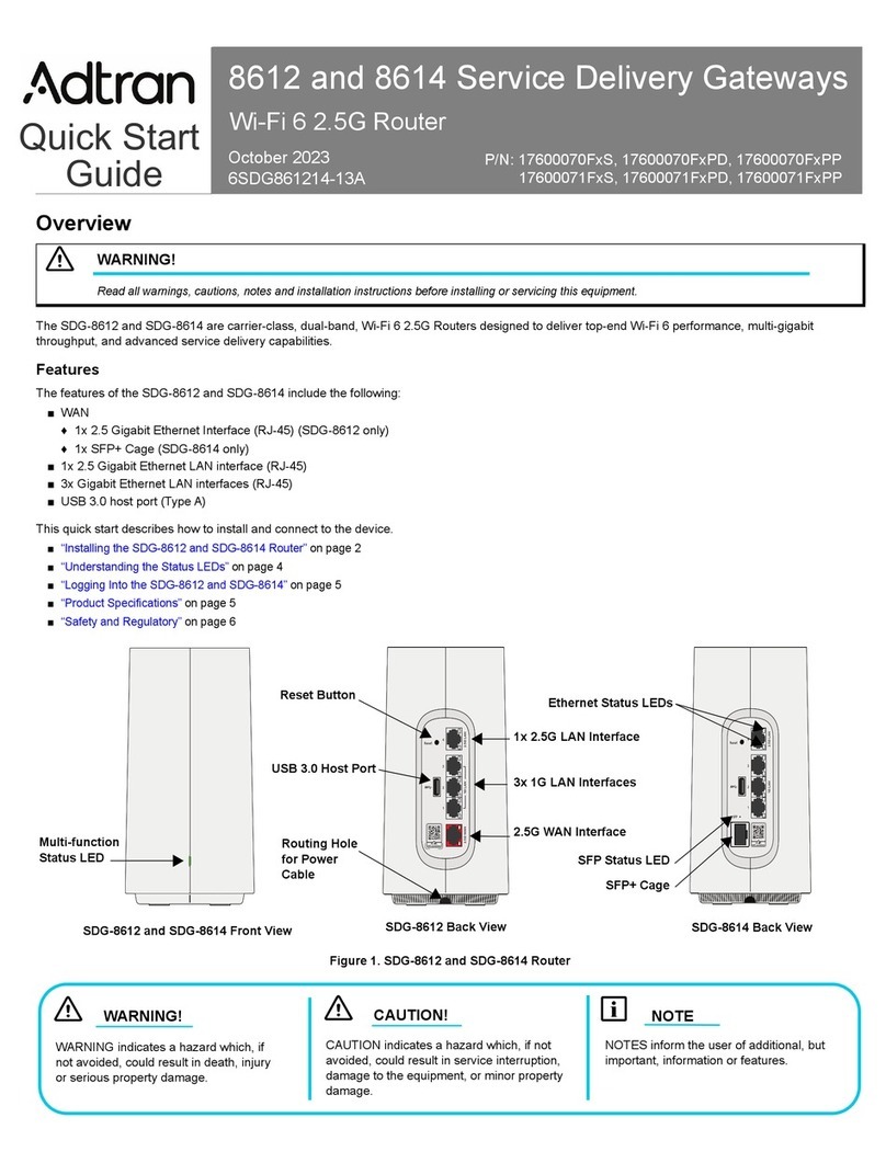
WAN
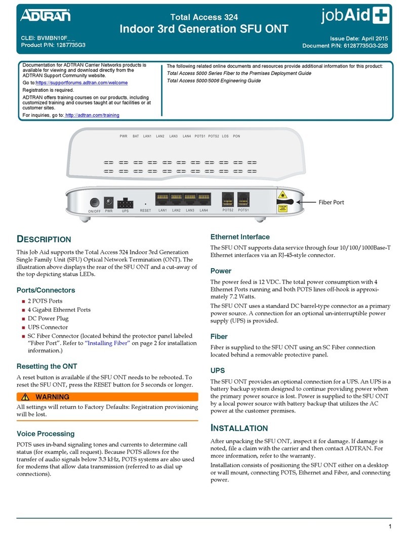
A stand-alone RJ45 port labeled WAN enables your SmartRG gateway to be hard-wired to another network device with a RJ45/Eth-
ernet output such as a cable, fiber, or DSL modem.
For models with a stand-alone, RJ45, WAN port and a DSL port, the WAN port can be re-purposed to function as an additional LAN
port when your internet connection is via DSL.
For instructions to enable this SmartPortTM feature, see the Ethernet Configuration section in this manual.
LAN
The four (yellow) RJ45 ports across the back of your gateway labeled LAN1, LAN2, LAN3, LAN4 are the means to connect client
devices such as computers and printers to your gateway.
On some models, one of these four ports may be labeled as WAN indicating SmartPortTM support. SmartPort allows a LAN port to be
re-purposed to function as an Ethernet WAN port (described above). When this port is serving as a LAN port, the corresponding LED
on the face of the unit is labeled "WAN"
For instructions to enable this SmartPortTM feature, see the Ethernet Configuration section in this manual.
USB
The two USB ports provide +5 DC volts of power. In addition, you can use these ports to configure a USB Mobile interface for your gate-
way.
POWER
Use only the power supply included with your gateway. Intended for indoor use only.
External Buttons
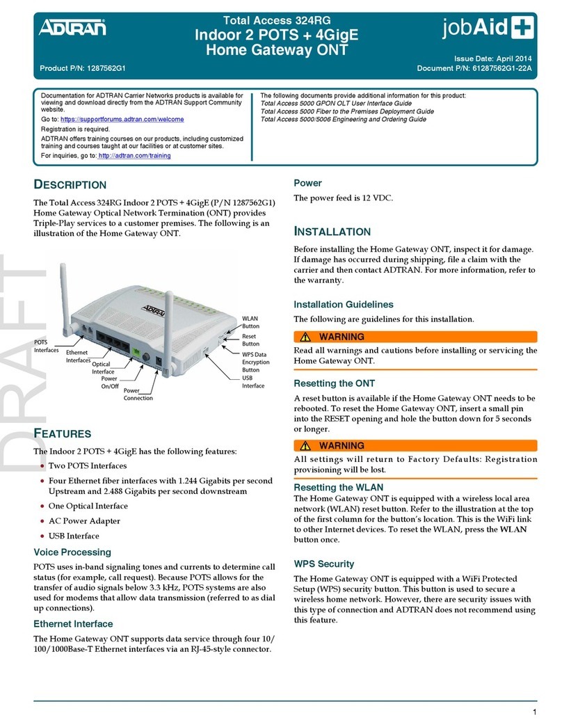
SmartRG gateways provide push-button controls on the exterior for critical features. These buttons provide a convenient way to trig-
ger WPS mode, toggle the WiFi radio on and off, or reset the gateway. Their presence and locations vary by model.
WPS Button
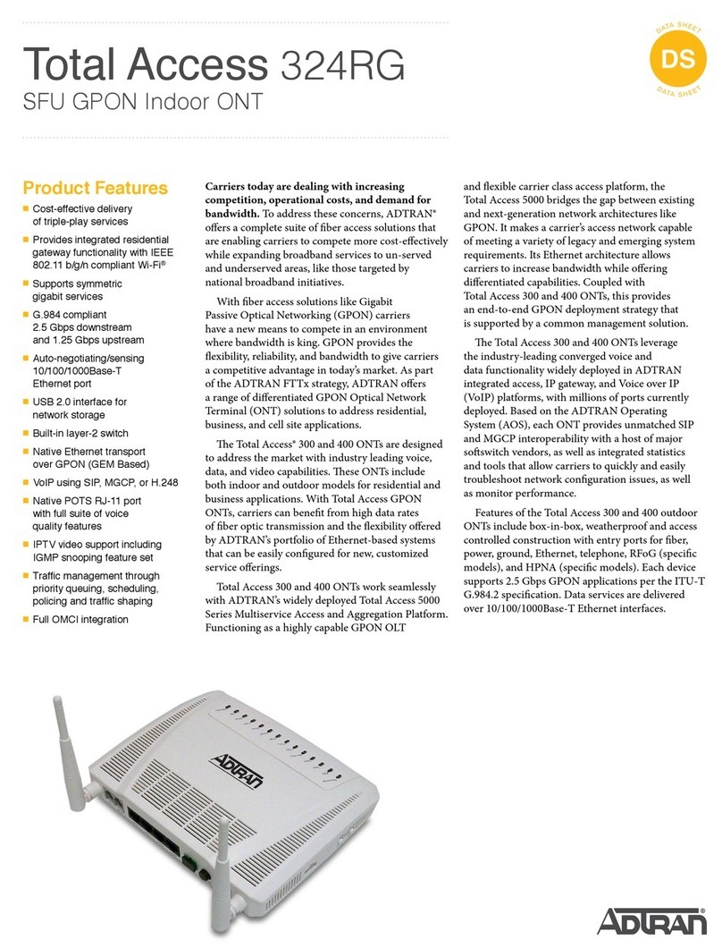
The WPS button triggers WPS (Wi-Fi Protected Setup™) mode. WPS is a standard means for creating a secure connection between
your gateway and various wireless client devices. It is designed to simplify the pairing process between devices.
This button is located on the top of the gateway. If you have client devices that support WPS, use this button to automatically con-
figure wireless security for your network.
WPS configures one client device at a time. You can repeat the steps as necessary for each additional WPS-compliant device you
wish to connect.
For specific instructions, refer to the Quick Start Guide included with your gateway. Also see the "Basic" section of this manual.


