ADTRAN Total Access 372E Product manual

installation guide
Total Access 372E
Active Ethernet Small Business Unit ONT
Installation and Maintenance Guide
Document Number: 61287723G1-5B
August 2014

Total Access 372E Active Ethernet Small Business Unit ONT Installation and Maintenance Guide
ii 61287723G1-5B
Trademarks
Any brand names and product names included in this document are trademarks, registered
trademarks, or trade names of their respective holders.
To the Holder of this Document
The contents of this document are current as of the date of publication. ADTRAN®reserves
the right to change the contents without prior notice.
In no event will ADTRAN be liable for any special, incidental, or consequential damages or
for commercial losses even if ADTRAN has been advised thereof as a result of issue of this
document.
About this Document
This document provides instructions for the installation and maintenance of the Active
Ethernet Small Business Unit ONT. The intended audience for this information is the craft-
person responsible for the installation and maintenance of the equipment. These instructions
assume familiarity with the intended use of the equipment, basic required installation skills,
and knowledge of local and accepted safety practices.
Related information can be obtained by referring to the applicable Component and System
documentation.
901 Explorer Boulevard
P.O. Box 140000
Huntsville, AL 35814-4000
United States
(256) 963-8000
©2014 ADTRAN, Inc.
All Rights Reserved.
®

61287723G1-5B iii
Revision History
Hazard Classifications
The following hazard classifications are used in this document:
DANGER
!
DANGER indicates a hazard with a high level of risk which, if not avoided,
will result in death or serious injury.
WARNING
!
WARNING indicates a hazard with a medium level of risk which, if not
avoided, could result in death or serious injury.
CAUTION
!
CAUTION indicates a hazard with a low level of risk which, if not avoided,
could result in minor or moderate injury. CAUTION can also be used to alert
against unsafe practices associated with events that could lead to personal
injury.
NOTICE
Notice call-outs indicate a potentially hazardous situation not related to
personal injury, such as messages related to property damage only.
NOTE
Notes inform the user of additional, but essential, information or features.
Revision Date Description
A August 2010 Initial release. This release supports Total Access
5000 System Release 5.5.
B August 2014 Corrected DS1 Pinout Table.

Total Access 372E Active Ethernet Small Business Unit ONT Installation and Maintenance Guide
iv 61287723G1-5B
Icons
The following icons are used throughout the ADTRAN document suite:
Training
ADTRAN offers training courses on our products. These courses include overviews on
product features and functions while covering applications of ADTRAN product lines.
ADTRAN provides a variety of training options, including customized training and courses
taught at our facilities or at customer sites.
For inquiries concerning training, contact ADTRAN:
Training Phone: 888-4ADTRAN (888-423-8726)
Training Fax: 256-963-6217
Training Email:tr[email protected]
deployment guide
installation guide
jobAid
reference guide
diagnostic guide
safety and regulatory
engineering guide
application guide
release notes
upgrade guide
user guide
manual

61287723G1-5B vii
Contents
Scope of this Guide . . . . . . . . . . . . . . . . . . . . . . . . . . . . . . . . . . . . . . . . . . . . . . 1
In this Guide . . . . . . . . . . . . . . . . . . . . . . . . . . . . . . . . . . . . . . . . . . . . . . . . . . . . 1
Related Documentation . . . . . . . . . . . . . . . . . . . . . . . . . . . . . . . . . . . . . . . . . . . 2
Description . . . . . . . . . . . . . . . . . . . . . . . . . . . . . . . . . . . . . . . . . . . . . . . . . . . . . 2
Features . . . . . . . . . . . . . . . . . . . . . . . . . . . . . . . . . . . . . . . . . . . . . . . . . . . . . . . . . . . 2
Modules and Housings . . . . . . . . . . . . . . . . . . . . . . . . . . . . . . . . . . . . . . . . . . . . . . . 3
Safety and Regulatory Compliance . . . . . . . . . . . . . . . . . . . . . . . . . . . . . . . . . 3
Components and Interfaces . . . . . . . . . . . . . . . . . . . . . . . . . . . . . . . . . . . . . . . 6
Mechanical Components . . . . . . . . . . . . . . . . . . . . . . . . . . . . . . . . . . . . . . . . . . . . . . 6
Outer Enclosure . . . . . . . . . . . . . . . . . . . . . . . . . . . . . . . . . . . . . . . . . . . . . . . . . 6
Outer Enclosure Security Locking Feature . . . . . . . . . . . . . . . . . . . . . . . . . . 6
Outer Enclosure with Cover Removed . . . . . . . . . . . . . . . . . . . . . . . . . . . . . 7
Electronics Module . . . . . . . . . . . . . . . . . . . . . . . . . . . . . . . . . . . . . . . . . . . . . . . 8
Circuit Board . . . . . . . . . . . . . . . . . . . . . . . . . . . . . . . . . . . . . . . . . . . . . . . . . . . . . . . 9
Data Processing . . . . . . . . . . . . . . . . . . . . . . . . . . . . . . . . . . . . . . . . . . . . . . . . . 9
Voice Processing . . . . . . . . . . . . . . . . . . . . . . . . . . . . . . . . . . . . . . . . . . . . . . . . 9
Alarm Reporting . . . . . . . . . . . . . . . . . . . . . . . . . . . . . . . . . . . . . . . . . . . . . . . . 10
SBU ONT Interfaces . . . . . . . . . . . . . . . . . . . . . . . . . . . . . . . . . . . . . . . . . . . . . . . . 10
Active Ethernet Interface . . . . . . . . . . . . . . . . . . . . . . . . . . . . . . . . . . . . . . . . . . 10
POTS Interface . . . . . . . . . . . . . . . . . . . . . . . . . . . . . . . . . . . . . . . . . . . . . . . . . 10
UPS Power Supply . . . . . . . . . . . . . . . . . . . . . . . . . . . . . . . . . . . . . . . . . . . . . . . . . 11
Installation . . . . . . . . . . . . . . . . . . . . . . . . . . . . . . . . . . . . . . . . . . . . . . . . . . . . 12
Shipping Contents . . . . . . . . . . . . . . . . . . . . . . . . . . . . . . . . . . . . . . . . . . . . . . . . . . 12
Required Tools . . . . . . . . . . . . . . . . . . . . . . . . . . . . . . . . . . . . . . . . . . . . . . . . . . . . 13
Necessary Supplies . . . . . . . . . . . . . . . . . . . . . . . . . . . . . . . . . . . . . . . . . . . . . 13
Instructions for Installing the SBU ONT . . . . . . . . . . . . . . . . . . . . . . . . . . . . . . . . . . 14
Determining SBU ONT Enclosure Location . . . . . . . . . . . . . . . . . . . . . . . . . . . 15
Mounting the Enclosure . . . . . . . . . . . . . . . . . . . . . . . . . . . . . . . . . . . . . . . . . . 16
Install the Electronics Module . . . . . . . . . . . . . . . . . . . . . . . . . . . . . . . . . . . . . . 17
Completed SBU ONT . . . . . . . . . . . . . . . . . . . . . . . . . . . . . . . . . . . . . . . . . . . . 18
Grounding the Buried Fiber . . . . . . . . . . . . . . . . . . . . . . . . . . . . . . . . . . . . 19
Ground Wire Connection . . . . . . . . . . . . . . . . . . . . . . . . . . . . . . . . . . . . . . 19
Alternative Grounding Method . . . . . . . . . . . . . . . . . . . . . . . . . . . . . . . . . . 21

Total Access 372 Active Ethernet Small Business Unit ONT Installation and Maintenance Guide
viii 61287723G1-5B
Local Power Source Wire Run . . . . . . . . . . . . . . . . . . . . . . . . . . . . . . . . . . 21
SBU ONT Power/Alarm Connector . . . . . . . . . . . . . . . . . . . . . . . . . . . . . . . 22
Installation of the Power Supply . . . . . . . . . . . . . . . . . . . . . . . . . . . . . . . . . . . . 24
Subscriber Connections . . . . . . . . . . . . . . . . . . . . . . . . . . . . . . . . . . . . . . . . . . 26
POTS Connections . . . . . . . . . . . . . . . . . . . . . . . . . . . . . . . . . . . . . . . . . . . 26
Install Ethernet Connections . . . . . . . . . . . . . . . . . . . . . . . . . . . . . . . . . . . . 27
Install DS1 Connections . . . . . . . . . . . . . . . . . . . . . . . . . . . . . . . . . . . . . . . 29
OptiTap Connections . . . . . . . . . . . . . . . . . . . . . . . . . . . . . . . . . . . . . . . . . 30
Commissioning and Testing . . . . . . . . . . . . . . . . . . . . . . . . . . . . . . . . . . . . . . 31
Turn-Up . . . . . . . . . . . . . . . . . . . . . . . . . . . . . . . . . . . . . . . . . . . . . . . . . . . . . . . . . . 31
Front Panel LEDs . . . . . . . . . . . . . . . . . . . . . . . . . . . . . . . . . . . . . . . . . . . . . . . 32
Secure the Unit . . . . . . . . . . . . . . . . . . . . . . . . . . . . . . . . . . . . . . . . . . . . . . . . . . . . 32
Test for POTS Line Faults . . . . . . . . . . . . . . . . . . . . . . . . . . . . . . . . . . . . . . . . . . . . 32
Provision Ethernet Interface at OLT . . . . . . . . . . . . . . . . . . . . . . . . . . . . . . . . . . . . 33
Troubleshooting . . . . . . . . . . . . . . . . . . . . . . . . . . . . . . . . . . . . . . . . . . . . . . . . 33
Faults Indicated with LEDs . . . . . . . . . . . . . . . . . . . . . . . . . . . . . . . . . . . . . . . . . . . 34
LEDs in Normal State . . . . . . . . . . . . . . . . . . . . . . . . . . . . . . . . . . . . . . . . . . . . 34
LEDs in Fault State . . . . . . . . . . . . . . . . . . . . . . . . . . . . . . . . . . . . . . . . . . . . . . 34
SBU ONT Trouble Isolation . . . . . . . . . . . . . . . . . . . . . . . . . . . . . . . . . . . . . . . . . . . 34
UPS Power LEDs . . . . . . . . . . . . . . . . . . . . . . . . . . . . . . . . . . . . . . . . . . . . . . . 34
NET Status LED Off . . . . . . . . . . . . . . . . . . . . . . . . . . . . . . . . . . . . . . . . . . . . . 35
POTS Troubleshooting . . . . . . . . . . . . . . . . . . . . . . . . . . . . . . . . . . . . . . . . . . . 35
ODN Interface Troubleshooting . . . . . . . . . . . . . . . . . . . . . . . . . . . . . . . . . . . . . . . . 36
Cleaning and Inspection of Components . . . . . . . . . . . . . . . . . . . . . . . . . . . . . 36
Cleaning Suggestions . . . . . . . . . . . . . . . . . . . . . . . . . . . . . . . . . . . . . . . . . 36
Cleaning the Connectors . . . . . . . . . . . . . . . . . . . . . . . . . . . . . . . . . . . . . . 37
Signal Level Verification . . . . . . . . . . . . . . . . . . . . . . . . . . . . . . . . . . . . . . . . . . 37
Downstream Signal Level Verification . . . . . . . . . . . . . . . . . . . . . . . . . . . . 37
Upstream Signal Level Verification . . . . . . . . . . . . . . . . . . . . . . . . . . . . . . . 38
UPS Communication Signals . . . . . . . . . . . . . . . . . . . . . . . . . . . . . . . . . . . . . . . . . . 39
Maintenance . . . . . . . . . . . . . . . . . . . . . . . . . . . . . . . . . . . . . . . . . . . . . . . . . . . 40
Specifications . . . . . . . . . . . . . . . . . . . . . . . . . . . . . . . . . . . . . . . . . . . . . . . . . . 40
Appendix A
Warranty and Customer Support . . . . . . . . . . . . . . . . . . . . . . . . . . . . . . A-1
Warranty. . . . . . . . . . . . . . . . . . . . . . . . . . . . . . . . . . . . . . . . . . . . . . . . . . . . . . . . . . . . A-1
ADTRAN Customer Care . . . . . . . . . . . . . . . . . . . . . . . . . . . . . . . . . . . . . . . . . . . . . . A-1
ADTRAN Sales. . . . . . . . . . . . . . . . . . . . . . . . . . . . . . . . . . . . . . . . . . . . . . . . . . . . . . . A-1
ADTRAN Technical Support. . . . . . . . . . . . . . . . . . . . . . . . . . . . . . . . . . . . . . . . . . . . A-1
ADTRAN Repair/CAPS . . . . . . . . . . . . . . . . . . . . . . . . . . . . . . . . . . . . . . . . . . . . . . . . A-1
Repair and Return Address . . . . . . . . . . . . . . . . . . . . . . . . . . . . . . . . . . . . . . . . . . A-1

61287723G1-5B ix
Figures
Figures
Figure 1. Enclosure and Electronics Module . . . . . . . . . . . . . . . . . . . . . . . . . . . . . . . . . . . 7
Figure 2. Electronics Module . . . . . . . . . . . . . . . . . . . . . . . . . . . . . . . . . . . . . . . . . . . . . . . 8
Figure 3. Uninterruptible Power Supply (UPS) . . . . . . . . . . . . . . . . . . . . . . . . . . . . . . . . . 11
Figure 4. Typical SBU ONT Installation . . . . . . . . . . . . . . . . . . . . . . . . . . . . . . . . . . . . . . 14
Figure 5. Enclosure Mounting Holes . . . . . . . . . . . . . . . . . . . . . . . . . . . . . . . . . . . . . . . . 16
Figure 6. Installing the Electronics Module . . . . . . . . . . . . . . . . . . . . . . . . . . . . . . . . . . . . 17
Figure 7. Completed SBU ONT . . . . . . . . . . . . . . . . . . . . . . . . . . . . . . . . . . . . . . . . . . . . 18
Figure 8. Cable Ground Installation . . . . . . . . . . . . . . . . . . . . . . . . . . . . . . . . . . . . . . . . . 19
Figure 9. SBU ONT Ground Connection . . . . . . . . . . . . . . . . . . . . . . . . . . . . . . . . . . . . . 20
Figure 10. Power/Alarm and UPS Connectors . . . . . . . . . . . . . . . . . . . . . . . . . . . . . . . . . . 22
Figure 11. Power/Alarm Connector . . . . . . . . . . . . . . . . . . . . . . . . . . . . . . . . . . . . . . . . . . 23
Figure 12. UPS Power Connection . . . . . . . . . . . . . . . . . . . . . . . . . . . . . . . . . . . . . . . . . . 24
Figure 13. POTS Connections . . . . . . . . . . . . . . . . . . . . . . . . . . . . . . . . . . . . . . . . . . . . . . 26
Figure 14. Ethernet and DS1 Cable Connections . . . . . . . . . . . . . . . . . . . . . . . . . . . . . . . 27
Figure 15. OptiTap Connection . . . . . . . . . . . . . . . . . . . . . . . . . . . . . . . . . . . . . . . . . . . . . 30
Figure 16. Network LED Flowchart . . . . . . . . . . . . . . . . . . . . . . . . . . . . . . . . . . . . . . . . . . 35
Figure 17. ODN Fiber Connection . . . . . . . . . . . . . . . . . . . . . . . . . . . . . . . . . . . . . . . . . . . 36
Figure 18. Downstream Test Configuration . . . . . . . . . . . . . . . . . . . . . . . . . . . . . . . . . . . . 38
Figure 19. Upstream Test Configuration . . . . . . . . . . . . . . . . . . . . . . . . . . . . . . . . . . . . . . 39

Total Access 372 Active Ethernet Small Business Unit ONT Installation and Maintenance Guide
x61287723G1-5B
TablesLi st of Tables
Tables
Table 1. Topic List . . . . . . . . . . . . . . . . . . . . . . . . . . . . . . . . . . . . . . . . . . . . . . . . . . . . . . . 1
Table 2. Related Documentation . . . . . . . . . . . . . . . . . . . . . . . . . . . . . . . . . . . . . . . . . . . . 2
Table 3. Modules and Housings . . . . . . . . . . . . . . . . . . . . . . . . . . . . . . . . . . . . . . . . . . . . 3
Table 4. Connector Pinout . . . . . . . . . . . . . . . . . . . . . . . . . . . . . . . . . . . . . . . . . . . . . . . 22
Table 5. UPS Pin-Out Connection . . . . . . . . . . . . . . . . . . . . . . . . . . . . . . . . . . . . . . . . . 25
Table 6. Ethernet Cable Pin-Outs . . . . . . . . . . . . . . . . . . . . . . . . . . . . . . . . . . . . . . . . . . 28
Table 7. Ethernet LEDs . . . . . . . . . . . . . . . . . . . . . . . . . . . . . . . . . . . . . . . . . . . . . . . . . . 28
Table 8. DS1 Cable Pin-Outs . . . . . . . . . . . . . . . . . . . . . . . . . . . . . . . . . . . . . . . . . . . . . 29
Table 9. Front Panel LEDs . . . . . . . . . . . . . . . . . . . . . . . . . . . . . . . . . . . . . . . . . . . . . . . 32
Table 10. Power LEDs . . . . . . . . . . . . . . . . . . . . . . . . . . . . . . . . . . . . . . . . . . . . . . . . . . . 34
Table 11. Downstream Power Level . . . . . . . . . . . . . . . . . . . . . . . . . . . . . . . . . . . . . . . . . 37
Table 12. Upstream Power Levels . . . . . . . . . . . . . . . . . . . . . . . . . . . . . . . . . . . . . . . . . . 38
Table 13. UPS Communication Signal Descriptions . . . . . . . . . . . . . . . . . . . . . . . . . . . . . 39
Table 14. Specifications . . . . . . . . . . . . . . . . . . . . . . . . . . . . . . . . . . . . . . . . . . . . . . . . . . 40

61287723G1-5B 1
Total Access 372
Active Ethernet Small
Business Unit ONT
Scope of this Guide
This document provides instructions for the installation and maintenance of the Total Access
372 Active Ethernet Small Business Unit ONT (SBU ONT), including LED descriptions,
regulatory information, and troubleshooting procedures.
In this Guide
This guide contains the topics listed in Table 1.
Table 1. Topic List
Topic See Page
Description 2
Safety and Regulatory Compliance 3
Components and Interfaces 6
Installation 12
Commissioning and Testing 31
Troubleshooting 33
Maintenance 40
Specifications 40

Total Access 372 Active Ethernet Small Business Unit ONT Installation and Maintenance Guide
261287723G1-5B
Related Documentation
Refer to Table 2 for additional, detailed information concerning the SBU ONT.
Description
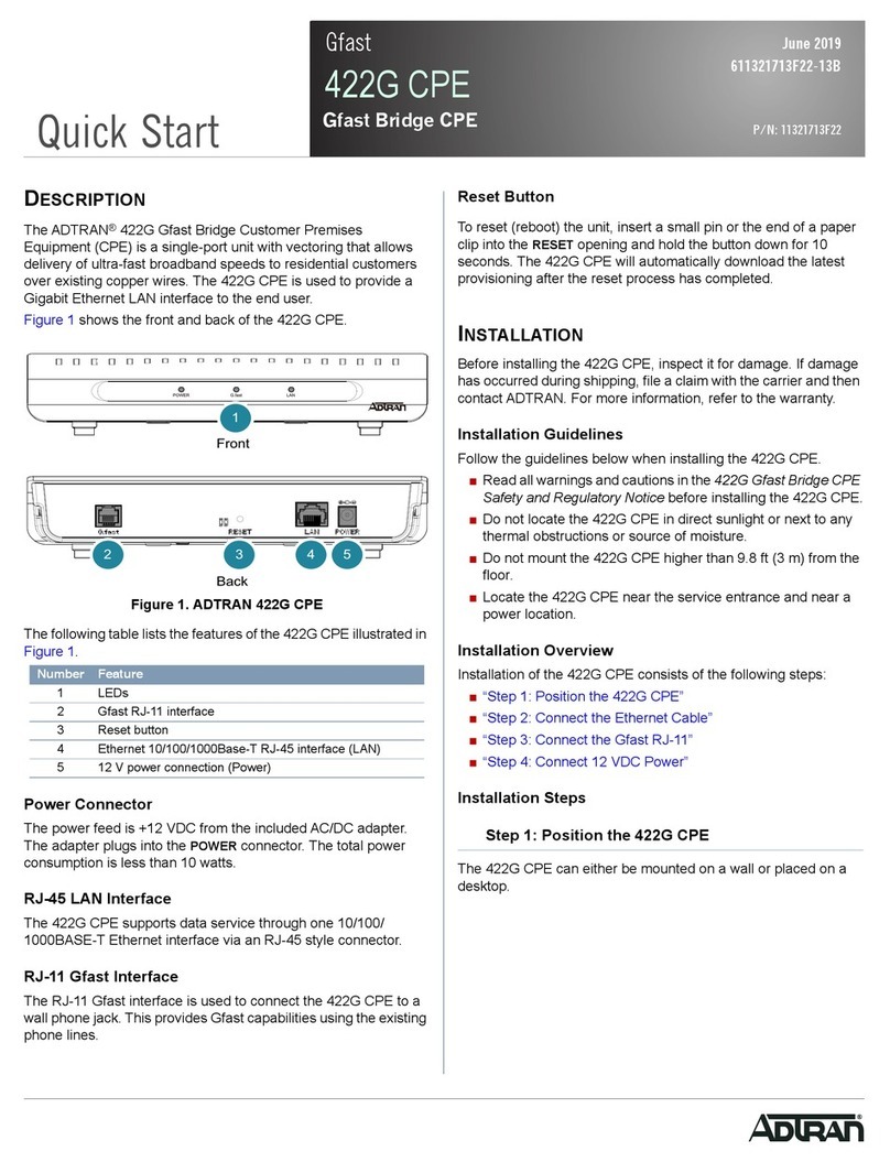
The Total Access®372E Active Ethernet Small Business Unit Optical Network Termi-
nation (SBU ONT) is an Active Ethernet Fiber-to-the-Premises (FTTP) ONT built to
address the needs of the small business. The SBU ONT includes the following features:
•EightPOTSports
• Four DS1 circuit emulated T1 interfaces (for PBX application)
• Two 10/100/1000 Ethernet interfaces
Optical technology provides a consistent and common approach to advancing the public
communications network.
The optical network consists of an Optical Line Terminal (OLT) located at the central office
(CO) and Optical Network Terminals (ONTs) located at the customer premises.
In order to allow for the transmission of downstream and upstream traffic on one single fiber,
different wavelengths are used for each direction. Downstream traffic uses 1490 nm, while
upstream traffic is carried on 1310 nm. The ONT employs optical diplexers to separate the
wavelengths.
Features
The basic features of the SBU ONT include the following:
• Box-in-box, weatherproof and access controlling construction
• Entry ports for fiber, power, ground, Ethernet, and telephone
• Reports four alarms from the UPS power supply
• Data services supported by up to two 10/100/1000Base-T Ethernet interfaces
• Basic telephone service supported by two POTS interfaces
• 12 VDC power supply
Table 2. Related Documentation
Title Part Number
Component Level Documentation
Total Access 372E Active Ethernet SBU ONT Job Aid 61287723G1-22
Total Access 372E Active Ethernet SBU ONT Safety and Regulatory Compliance
Notice
61287723G1-17
Total Access 5000 24-Port Active Ethernet OLT Job Aid 61187560F1-22
System Level Documentation
Total Access 5000 Series Fiber to the Premises Deployment Guide 65K85FTTP-50

Safety and Regulatory Compliance
61287723G1-5B 3
Modules and Housings
This manual covers the following electronic modules and housings:
NOTE
The Total Access 372E SBU ONT is only intended to be used with the Corning
Systems Model FNI-NG series outdoor NID housing.
Safety and Regulatory Compliance
WARNING
!
• The 10/100/1000Base-T port(s) and POTS are classified as Type 4 as
defined in Appendix B of GR-1089-CORE, Issue 4, and is suitable for
connection to intra-building or unexposed wiring or cabling only. Do not
metallically connect these ports to interfaces which connect to the Outside
Plant (OSP) or to the OSP wiring. The 10/100/1000Base-T ports and POTS
are designed for use as an intra-building interface only (Type 4 ports as
described in GR-1089-CORE, Issue 4) and require isolation from exposed
OSP cabling. The addition of Primary Protectors is not sufficient protection
in order to connect this interface metallically to OSP wiring.
• The DS1 port(s) are classified as Type 3, 4 or 5, as defined in Appendix B of
GR-1089-CORE Issue 5. If deployed as type 3, or 5 the ports meet the
lightning and power fault criteria with any primary protector that meets
any of the voltage limits of GR-974- CORE or GR-1361-CORE (that is,
carbon blocks, gas tubes, and so forth). If deployed as Type 4 primary
protectors are not required.
Table 3. Modules and Housings
Total Access 372E Description
1287723G1 Total Access 372E SBU Electronics Module
1187774G1 Standard SBU Housing
1187775G1 SBU OptiTap Housing

Total Access 372 Active Ethernet Small Business Unit ONT Installation and Maintenance Guide
461287723G1-5B
CAUTION
!
Electrostatic Discharge (ESD) can damage electronic components. When
handling modules, wear an antistatic discharge wrist strap to prevent
damage to electronic components. Place modules in antistatic packing
material when transporting or storing. When working on modules, always
place them on an approved antistatic mat that is electrically grounded.
CAUTION
C
The optical installation is intended to be installed by trained service
personnel only. This is a ‘Class 1 Laser Product’.
CAUTION
!
• For continued compliance with applicable Laser Safety Standards, only
approved ‘Class 1 Laser Product’ modules from Adtran’s approved vendor
list (located on the ADTRAN website, www.adtran.com) should be
installed in the product.
• The Total Access 372 is a Class 1 Laser Module and complies with the Laser
Safety requirements of FDA 21 CFR 1040.10 and 1040.11, and EN60825-1
and -2.
• The Total Access 372 is NRTL Listed to the applicable UL safety standards.
•The Total Access 372 is designed to be deployed in GR-3108-CORE
environmental class 4 as defined in GR-3108-CORE issue 2.
• The Total Access 372 is intended for deployment where the NEC applies
(for example, Customer Premises) and is intended to be installed by trained
service personnel.
• The Total Access 372 is to be serviced by Qualified Service personnel only.
• This product has been evaluated to international safety standards EN
60950-1, AS/NZS 60950.1, and IEC 60950-1. This product meets the
requirements for CE marking under the EMC Directive and Low Voltage
Directive. Standards used to demonstrate Compliance are EN 300 386 and
EN 60950.
C A U T I O N
C A U T I O N
!
SUBJECT TO ELECTROSTATIC DAMAGE
OR DECREASE IN RELIABILITY.
HANDLING PRECAUTIONS REQUIRED.

Safety and Regulatory Compliance
61287723G1-5B 5
NOTE
• The main feed is optical and therefore not classified as any type of port as
defined in Appendix B of GR-1089-CORE Issue 5.
• The Total Access 372 SBU ONT Chassis frame ground terminal must be
connected to an earth ground to ensure the SBU ONT is properly
grounded.
• Power supply input and output conductors of equipment which are
outside of the building, are intended to be less that 100 feet (30.5 meters)
and have adequate clearance from power and lightning conductors in
accordance with NEC 725 and 800. Final acceptance of the Listed
equipment installation will ultimately be up to the local Authority Having
Jurisdiction (AHJ).
This device complies with Part 15 of the FCC rules. Operation is subject to the following two
conditions:
1. This device may not cause harmful interference.
2. This device must accept any interference received, including interference that may cause
undesired operation.
Changes or modifications not expressly approved by ADTRAN could void the user’s
authority to operate this equipment.
This product is designed to meet the following environmental classes:
• ETSI EN 300 019-1-1 “Classification of environmental conditions; Storage”, Class 1.2
• ETSI EN 300 019-1-2 “Classification of environmental conditions, Transportation”, Class
2.3
• ETSI EN 300 019-1-4 “Classification of environmental conditions, Stationary use at non-
weatherprotected locations”, Class 4.2H
The equipment is designed to function without degradation during exposure to all test sever-
ities per Class 4.2H of ETSI EN 300 019-1-4.
This product complies with ETSI EN 300 386 “Electromagnetic compatibility and Radio
spectrum Matters (ERM); Telecommunication network equipment; Electromagnetic Compati-
bility (EMC) requirements.”
This product meets the EU RoHS Directive 2002/95/EC and/or applicable exemptions. Refer
to www.adtran.com for further information on RoHS/WEEE.

Total Access 372 Active Ethernet Small Business Unit ONT Installation and Maintenance Guide
661287723G1-5B
Components and Interfaces
The SBU ONT consists of the following components and interfaces:
• Mechanical Components
• Electronics Module
• Circuit Board
Mechanical Components
The SBU ONT is designed for outdoor or indoor applications. The Corning Systems Model
FNI-NG series outdoor Network Interface device (NID) housing is intended as a demarcation
point between the Telco and a subscriber premise. The NID housing is used in both indoor
and outdoor installations.
Outer Enclosure
The Outer Enclosure provides both environmental control (weatherproofing) and access
control.
Outer Enclosure Security Locking Feature
The enclosure is intended for use on the outside of a building and is designed to meet US
environmental requirements. The unit is weather hardened and is able to withstand 70 m.p.h.
wind driven rain, high temperature, cold temperature, drop tests and all other GR-49,
GR-950, and GR-487 requirements. The dimensions are approximately 15” high x 12” wide x
4” deep (381 mm x 305 mm x 102 mm). The external door provides access to the RJ-11 POTS
connectors, Ethernet RJ-45 connectors, and DS1, RJ-45 connectors. The enclosure door is held
in the closed position by two “snap” door retainers. To open the door these two snaps must be
disengaged at the same time.
The Outer Enclosure Door has a double security locking feature provided by the third molded
part. This provides the following capabilities:
• Subscriber access door is closed using a flat head screw
• Telco personnel can control access via the Pin-in-Hex screw

Components and Interfaces
61287723G1-5B 7
Outer Enclosure with Cover Removed
The Outer Enclosure base (refer to Figure 1) contains cable entry points for power, ground,
Telco incoming cabling and cabling to the customer premises. Each cable entry has grommets
to provide environmental protection. The cable entries also support strain relief with Tie-
wraps.
Figure 1. Enclosure and Electronics Module
NOTE
In the figure above, the cover for the SBU ONT has been removed for clarity
purposes.
Telco Access Screw
Surface Mounting
Hole
Surface
Mounting
Hole
TELEPHONETROUBLESHOOTING:
1.Identify the bad line (POTS 1-8).
2.Plug any working phone into
the appropriate jack.
If the telephone works, the unit
isfunctioning normally.
If the telephone does not work,
contactyourservice provider.
3.Remove the telephone from the
POTSjack.
TOTALACC ESS 372
1287722G1

Components and Interfaces
61287723G1-5B 9
Circuit Board
WARNING
!
Do not open the Electronics Module or attempt to remove the Circuit Board
from the Electronics Module.
The SBU ONT contains a single circuit board contained within the Electronics Module that
provides the following functions:
• Data Processing
• Voice Processing
• Alarm Reporting
Data Processing
The following data processing functions are performed:
• Traffic management (priority queuing, scheduling, policing, and traffic shaping)
• Up to 16 VLANs
• IGMP Snooping
• QoS with four traffic classes per IEEE 802.1p
• Full IEEE 802.1Q VLAN ID processing per port
• 64 byte to 1600 byte packet sizes
Voice Processing
The POTS Voice Processing feature set is listed below:
• Echo cancellation per ITU-T G.168 - up to 16 ms tails
• Caller ID FSK tone generation
• Fixed or adaptive jitter buffer
• modem, fax tone detection
• DTMF detection/generation
• RTP/RTCP
• Silence suppression
• Comfort noise generation
•SIP
•MGCP
• GR-303
• RFC 2833
• Voice activity detection
• Configurable framing size - 10 ms, 20 ms, or 30 ms
• G.711, G.729AB

Total Access 372 Active Ethernet Small Business Unit ONT Installation and Maintenance Guide
10 61287723G1-5B
Alarm Reporting
The circuit board provides alarm reporting for the Uninterruptible Power Supply (UPS). The
following alarms are supported:
•LowBattery
• Battery Missing
• Replace Battery
•OnBattery
SBU ONT Interfaces
The SBU ONT supports the following interfaces:
• Active Ethernet Network
•Eight(8)POTS
• Four (4) DS1
• Two (2) 10/100/1000 Ethernet Connections
•Power
Active Ethernet Interface
The SBU ONT supports data services through two 10/100/1000Base-T Ethernet interfaces via
the front access RJ-45 connectors. The Active Ethernet interface meets IEEE 802.3 specifica-
tions and is transformer coupled for 1500 V isolation. The connector has built-in LEDs for data
activity indications. Both full and half duplex modes are supported.
POTS Interface
The telephone service or POTS connection is provided through pivot-connectors located on
the right side of the Electronics Module. The RJ-11 jacks are used to provide fault isolation.
Inserting an RJ-11 jack (i.e., telephone cable or telephone test set) will connect the telephone
set to the SBU ONT and also disconnect the subscriber service from the SBU ONT providing
fault isolation to the SBU or premises wiring. The POTS Interface feature set is listed below:
• 5 REN per port
• Loop start
• Loop supervision detecting and reporting
• 50, 60, 70 Vrms integrated ringing
•μ-law or a-law voice coding
• 30 mA loop current
• Integrated GR-909 testing

Components and Interfaces
61287723G1-5B 11
UPS Power Supply
The uninterruptible power supply (UPS) provides 12 VDC to the SBU ONT. An UPS (see
Figure 3) is a battery backup system designed to continue providing power when the primary
power source is lost. When the UPS senses a loss of power from the primary source, the
backup battery is activated to provide power for a short period of time.
Figure 3. Uninterruptible Power Supply (UPS)
Power is supplied to the SBU ONT by an UPS local power source with battery backup that
uses the AC power at the customer premises. The unit powers the SBU ONT and functions as
a battery backup supplying continuous 12 VDC. It contains one sealed, lead-acid battery for
power backup.
If the battery is disconnected, the SBU ONT is not protected from power outages, and will
send a “Battery Missing” alarm to the OLT.
Install the UPS per the specifications recommended by the manufacturer.
ONT Power Converter
Battery Charger
Alarms
Battery
Backup
Alarms
12V DC
85V AC-
264V AC
UPS

Total Access 372 Active Ethernet Small Business Unit ONT Installation and Maintenance Guide
12 61287723G1-5B
Installation
CAUTION
!
Electrostatic Discharge (ESD) can damage electronic components. When
handling modules, wear an antistatic discharge wrist strap to prevent
damage to electronic components. Place modules in antistatic packing
material when transporting or storing. When working on modules, always
place them on an approved antistatic mat that is electrically grounded.
After unpacking the SBU ONT, inspect it for damage. Before planning the installation of the
SBU ONT, the technician should do the following to verify component integrity.
1. Unpack both the SBU ONT and power supply (packed separately) to ensure the units are
visibly intact and are not missing any components.
2. Examine the SBU ONT enclosure, fiber management guide, associated terminals,
weather resistant grommets, fiber connector, telephone and Ethernet ports for usability.
3. Examine the power supply to ensure that the UPS, battery and power cord are present
and sound.
If damage has occurred, file a claim with the carrier then contact ADTRAN Customer Service.
Refer to “Appendix A, Warranty and Customer Support” for further information. If possible,
keep the original shipping container for returning the SBU ONT for repair or for verification
of shipping damage.
Shipping Contents
The contents include the following items:
• Total Access 372E Electronics Module
•Total Access 372E SBU ONT Job Aid (P/N 61287723G1-22)
•Total Access 372E SBU ONT Safety and Regulatory Compliance Notice (P/N 61287723G1-17)
C A U T I O N
C A U T I O N
!
SUBJECT TO ELECTROSTATIC DAMAGE
OR DECREASE IN RELIABILITY.
HANDLING PRECAUTIONS REQUIRED.
Other manuals for Total Access 372E
1
Table of contents
Other ADTRAN Modem manuals

ADTRAN
ADTRAN Express XRT User manual

ADTRAN
ADTRAN 6540 Operating and installation instructions

ADTRAN
ADTRAN 6540 User manual

ADTRAN
ADTRAN 1200051L1 User manual

ADTRAN
ADTRAN TSU ACE User manual

ADTRAN
ADTRAN Gfast 422G User manual

ADTRAN
ADTRAN 3G CDMA NIM User manual

ADTRAN
ADTRAN DSU III ARdc User manual

ADTRAN
ADTRAN XR User manual

ADTRAN
ADTRAN 1200861L1 User manual