For more information, refer to the Installation and Maintenance Practice (P/N 61230001L1-5) available online at www.adtran.com.
*61230007L1-22B* ©2006 ADTRAN, Inc. All
Rights Reserved.
61230007L1-22B
0612
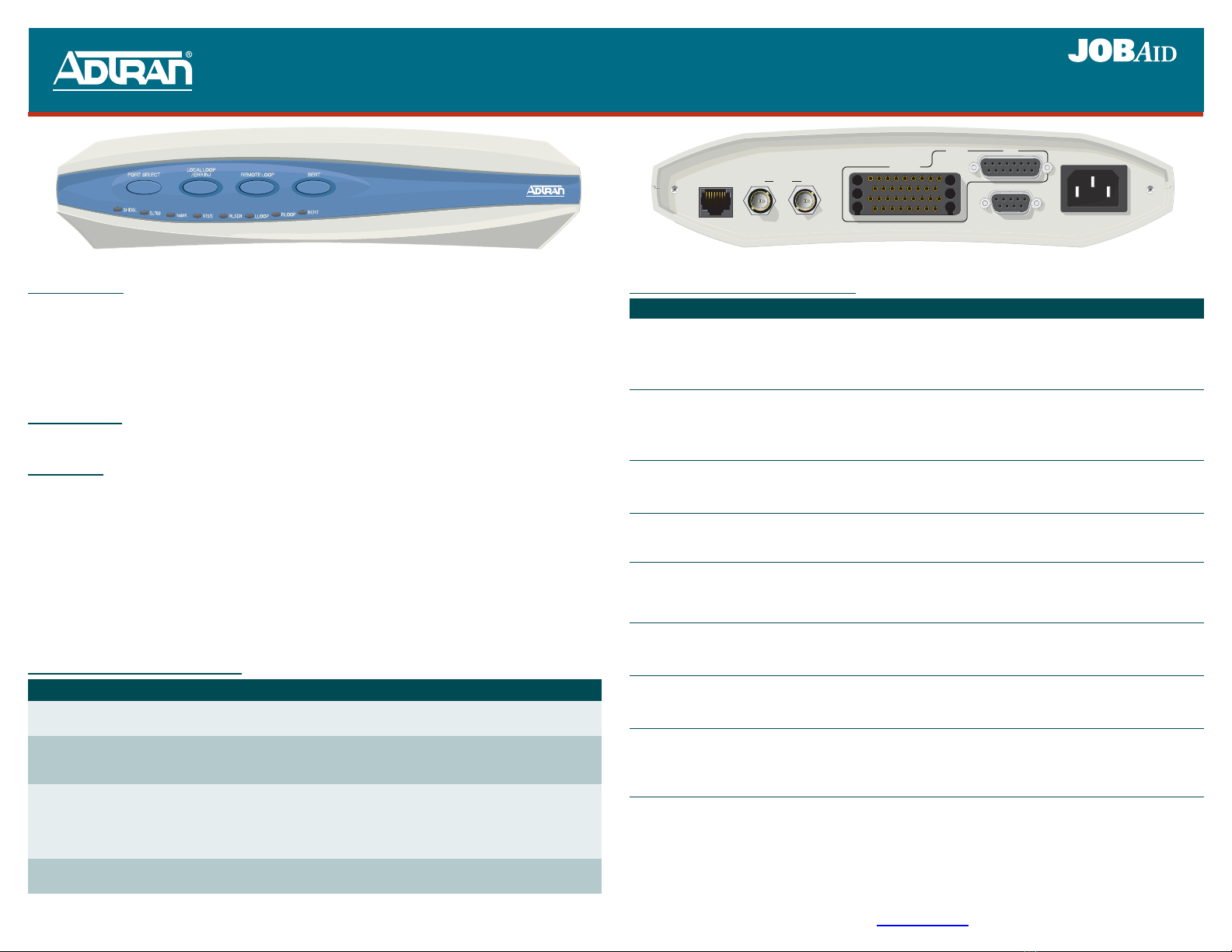
6541 SHDSL 2-Wire/4-Wire NTU, AC Powered
Express 6500 Series
6541 Front Panel
SHDSL
X.21
V.35/V.36
CONTROL V.28
100-240VAC 50/60Hz 100mA
Nx64K
6541 Rear Panel
TX RX
G.703
LED INDICATOR FUNCTIONALITY
1. Minor SHDSL port alarms: CRC errors, Loop Attenuation Threshold Alarm, SNR Margin Threshold Alarm, Segment
Anomaly, and any ES, SES, UAS, CVC, and LOSWS 15-Minute Threshold Alarm
2. Major SHDSL port alarms: LOS, LOSW, or Segment Defect
3. Minor G.703 port alarms: Rx RAI, Frame Slip, CRC-4 errors, LBER, and any ES, SES, UAS, and CVC 15-Minute
Threshold Alarm
4. Major G.703 port alarms: LOS, LOF, LOMF, Rx AIS, or HBER
5. Nx64K port alarms: Clock Slip, Loss of External Clock, FIFO Underflow/Overflow, and Inactivity Alarm
Label Status Description
SHDSL {
z
z
z
Off
Green
Yellow
Red
Unit is powered off
Port is trained; no active alarms
Port is trained with a minor active alarm (1)
Port is attempting to or is trained with a major alarm (2)
G. 7 0 3 {
z
z
z
Off
Green
Yellow
Red
Port is not active
Active Port with no active alarm
Active Port with a minor alarm (3)
Active Port with a major alarm (4)
Nx64K {
z
z
Off
Green
Red
Port is not active
Active Port with no active alarm
Active Port with an active alarm condition (5)
RTS/C {
z
Off
Green
Nx64K port is not active or when active, V.35/V.36 “Request To Send” or X.21
“Control” line from the DTE is off
V.35/V.36 “Request To Send” or X.21 “Control” line from the DTE is on
RLSD/I {
z
Off
Green
Nx64K port is inactive or when active, V.35/V.36 “Receive Line Signal Detector” and
X.21 “Indication” control line from the NTU is off.
V.35/V.36 “Receive Line Signal Detector” or X.21 “Indication” control line from the
NTU (DCE) is on
LLOOP {
z
z
Off
Yellow
Red
Local Loop is not active
Active Local Loopback on the selected port
Active Local Loop on one or more ports or services (when no port is selected)
RLOOP {
z
z
Off
Yellow
Red
Remote Loop is not active
Active Remote Loopback on the selected port (when determined via established EOC)
Active Remote Loop on one or more ports or services (when no port is selected)
BERT {
z
z
z
Off
Green
Yellow
Red
BERT is not active
Active BERT and the test pattern detector is synchronized with no received bit errors
Active BERT and one or more test pattern bit errors have been received
Active BERT but the test pattern detector is not synchronized
DESCRIPTION
The AC powered ADTRAN 6541 SHDSL 2-Wire/4-Wire NTU (P/N 1230007L1) functions as an
interface between the SHDSL network and the Data Terminal Equipment (DTE) for applications such
as LAN-to-LAN bridging, Frame Relay circuit, and PABX termination. The 6541 is designed to be
used either as a remote unit to the ADTRAN Total Access®3000 multiservice platform, or as a pair of
units in a point-to-point limited distance campus configuration, with one 6541 configured to “LT”
mode.
COMPLIANCE
EN 300 386-2; IEC 60950/EN 60950/AS NZS60950; S016; S043.2; ITU K.21 Enhanced; Telstra 1555.
FEATURES
The 6541 has the following features:
♦Housed in a standalone plastic case
♦Provides four front panel recessed pushbuttons and eight front panel LED indicators
♦Provides SHDSL, G.703 and/or Nx64K ports, and a local management port
♦Provides a rear panel local power AC connection
♦Provides bad splice protection using the ADTRAN proprietary Runtime TScan™2.0 splice
protection feature (for more information on this feature and how to locally manage TScan, refer to
the SHDSL 2-Wire/4-Wire NTU Product Series Installation and Maintenance Practice, P/N
61230001L1-5)
PUSHBUTTON FUNCTIONALITY
Pushbutton Description
PORT SELECT Press the PORT SELECT button to select the active port. Selection choices cycle through the
following order: No Port, Nx64k, G.703, SHDSL.
LOCAL LOOP/
ERR INJ If a port is selected, and a Bit Error Rate Test (BERT) is not in progress, press the LOCAL
LOOP/ERR INJ button to initiate or terminate a local loop on the selected port. If a BERT is
in progress, press the button to inject a single bit error.
REMOTE LOOP If the SHDSL port is selected, press the REMOTE LOOP button to place or remove a remote
loop on the port by sending a EOC request message to the LTU (or NTU in campus mode). If
the Nx64K port or G.703 port (with only one service defined) is selected, press this button to
place or remove a remote loop on the selected port's single data service by sending respective
inband loop up or loop down patterns to the far end (in the associated data service timeslots).
BERT If a port is selected and there are no local loops, press the BERT button to start or stop a
BERT on the selected port.


