manuals.online logo
Brands
  1. Home
  2. •
  3. Brands
  4. •
  5. ADTRAN
  6. •
  7. Network Hardware
  8. •
  9. ADTRAN DS3 NIU3 User manual

ADTRAN DS3 NIU3 User manual

DS3 NIU3
WITH PERFORMANCE MONITORING
JOBAID
61212075L2-22D
0312
DS3 NIU3
CLEI: NCD3EGNA_ _
C A U T I O NC A U T I O N !
SUBJECT TO ELECTROSTATIC DAMAGE
OR DECREASE IN RELIABILITY.
HANDLING PRECAUTIONS REQUIRED.
GENERAL
This job aid is used in association with the standalone housing job aid (P/N 61212070L1-22), 12-slot
shelf job aid (P/N 61212078L1-22), or 3-slot shelf job aid (P/N 61212073L1-22).
LED INDICATION
STATUS ●●Off No power.
●Green Normal operation.
●Red Card malfunction.
NTWK LOS/AIS ●●Off DS3 signal present at network interface.
●Amber AIS (Alarm Indication Signal) present at network interface.
●Red DS3 signal not present at network interface.
NTWK C-BIT ●●Off C-Bit framing not detected at network interface.
●Green C-Bit framing present at network interface.
●Amber C-Bit framing present, Tx idle.
NTWK M13 ●●Off M13 framing not detected at network interface.
●Green M13 framing present at network interface.
●Amber M13 framing present, Tx idle.
NTWK LBK ●●Off Loopback toward network disabled, network pattern test disabled.
●Amber Loopback toward network enabled.
✷
✷Flashing Slow: Network pattern test active. Fast: Loopback arming.
CUST LOS/AIS ●●Off DS3 signal present at customer interface.
●Amber AIS present at customer interface.
●Red No DS3 signal at customer interface.
CUST C-BIT ●●Off C-Bit framing not detected at customer interface.
●Green C-Bit framing present at customer interface.
CUST M13 ●●Off M13 framing not detected at customer interface.
●Green M13 framing present at customer interface.
CUST LBK ●●Off Loopback toward customer disabled, customer pattern test disabled.
●Amber Loopback toward customer enabled.
✷
✷Flashing Slow: Customer pattern test active. Fast: Loopback arming.
FUSE ALARM ●●Off Normal.
●Red Circuit board fuse failed.
NOTE: All LEDs Off indicates no power, or other system malfunction.
INSTALLATION
After unpacking the unit, inspect it for damage. If damage is noted, file a claim with the carrier, then
contact ADTRAN. See Warranty section.
See Note in Compliance section. The DS3 Network Interface Unit with Performance Monitoring
(NIU3 PM) provides a demarcation and loopback point for DS3 circuits. The NIU3 PM can deploy as
a single unit, a 3-unit horizontal shelf, or a 12-unit vertical shelf.
Transmission Distance
The NIU3 PM can pass both network and customer signals up to 900 feet. During NIU3 bypass
operations, if total transmission distance exceeds 900 feet, DS3 data may cease. The DS3 NIU3 is not
intended for use as a repeater. See the Operation Diagram to the right for maximum recommended
transmission distance.
Network and Customer Connections, Power & Fuse
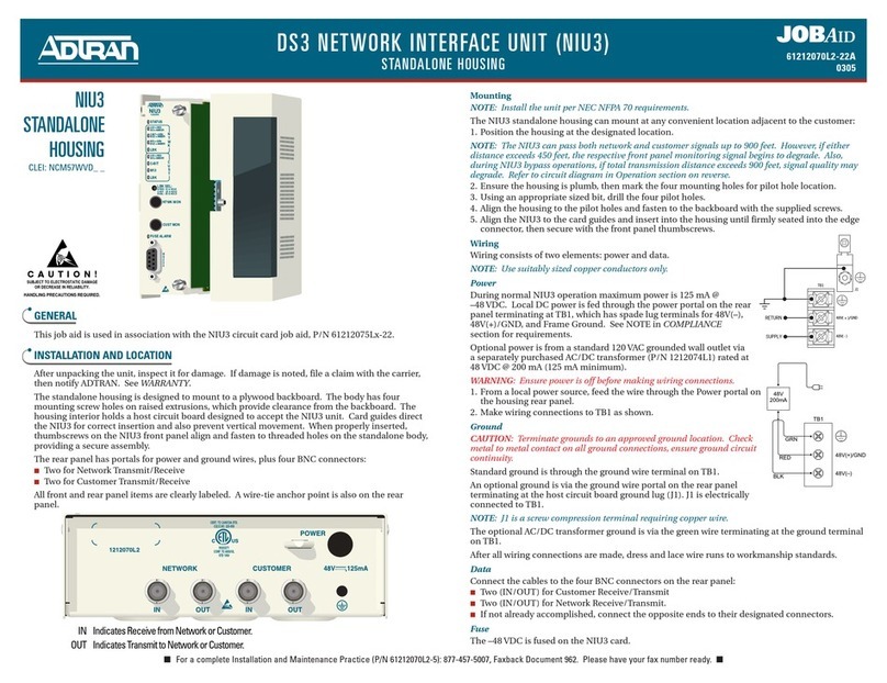
Each housing has four rear panel BNC connectors for each NIU3 PM: two (IN/OUT) for customer
receive/transmit, and two (IN/OUT) for network receive/transmit. The NIU3 PM operates on local
–48 VDC or –24 VDC. During normal operation, maximum power is 125mA @ –48 VDC or 250 mA@
–24 VDC. Power is fused on each NIU3 PM card.
TURNUP
When inserted into a host with power, the STATUS LED turns On red while the NIU3 PM
performs a self-test. If the self-test passes, the STATUS LED turns On green, and the remaining
LEDs go through an On/Off sequence, indicating the NIU3 PM is online. If the test fails, the STA-
TUS LED remains red, and the host bypass relays maintain data flow around the NIU3 PM.
OPERATION
During operation, the NIU3 PM is transparent to the network. If the NIU3 PM malfunctions, is
removed, or loses power, bypass relays on the host circuit board engage and maintain data flow
around the NIU3 PM.
Monitoring
Front panel monitoring jacks provide nonintrusive access through a high-impedance bridging
circuit. The monitor level is nominally 21.5 dB below the signal power. The signal being
transmitted to the network is monitored via the NTWK MON jack; the signal being transmitted
to the customer is monitored via the CUST MON jack.
Loss of Signal
During a loss of signal defect, the NIU3 PM provides both a “keep alive”signal and LED
notification.
■If there is no signal from the network, the NTWK LOS/AIS LED turns On red, and the NIU3
PM transmits an unframed all-ones signal toward the customer.
■If there is no signal from the customer, the CUST LOS/AIS LED turns On red, and the NIU3
PM transmits the keep-alive signal selected on the Provisioning Terminal screen. This signal
is transmitted toward the network.
Loss of Framing
If either NTWK or CUST C-Bit and M13 LEDs are both Off, the associated network or customer
signal is unframed.
TESTING
The NIU3 PM is compatible with standard test equipment. Digital testing is accomplished with a
T-Berd 310 or equivalent. The test device at the CO inserts a DS3 NIU FEAC loop up code (C-Bit
parity framing only) toward the NIU3 PM. The NIU3 PM then performs a network loopback. The
loopback is terminated by a DS3 NIU FEAC loop down code. Network and customer loopbacks
can also be enabled or terminated with the front panel LBK SEL pushbutton or via the craft
interface.
In-band Test Codes
Remote testing can also be conducted using in-band test codes. The CO test device inserts the
arming code 1011100 for 5 seconds. After 5 seconds, the test device has 20 seconds to transmit
one of the following test identifier codes:
■11010011 11010011 D3D3h Loopback ■11010111 01000001 D741h Blue
■00101110 00100011 2E23h 2^23-1 ■00101110 00100000 2E20h QRSS
■11010111 01000010 D742h Idle ■11010111 01000011 D743h User Defined
The first code initiates a loopback at the customer interface in the network direction. The
remaining codes send the associated test pattern in both network and customer directions
simultaneously. To deactivate a loopback or test pattern, send 1110110. NIU test patterns are
framed according to framing of the incoming signal at the NIU NTWK interface at the moment
an NIU in-band test pattern is activated. The User Defined test pattern is set to the last test
pattern programmed on the NIU Loopbacks and Test screen.
■ For a complete Installation and Maintenance Practice (P/N 61212075L2-5): 877-457-5007, Faxback Document 881. Please have your fax number ready. ■
LBK SEL:
NTWK: 1X & HOLD
CUST: 2X & HOLD
DUAL: 3X & HOLD
NTWK MON
N
T
W
K
C
U
S
T
NIU3
1212075
CUST MON
STATUS
LOS = RED
AIS = AMBER
C-BIT = GRN
IDLE = AMBER
M13 = GRN
IDLE = AMBER
LBK
LOS = RED
AIS = AMBER
C-BIT
M13
LBK
FUSE ALARM
R
S
2
3
2
PRICING AND AVAILABILITY 800.827.0807
TECH SUPPORT 800.726.8663
RETURN FOR REPAIR 256.963.8722
www.adtran.com
61212075L2-22D
DS3 NIU3
WITH PERFORMANCE MONITORING
Pushbutton Loopback
Front panel LBK SEL pushbutton (SW1) controls loopback mode as described here:
■To initiate a network loopback, press SW1 once and hold for 5 seconds. The NTWK LBK LED flashes rapidly,
indicating the network loopback is “arming.”After 5 seconds, the network loopback enables, the NTWK LBK LED
turns On solid, and SW1 can be released.
■To initiate a customer loopback, press SW1 twice and hold for 5 seconds. The CUST LBK LED flashes rapidly,
indicating the customer loopback is “arming.”After 5 seconds, the customer loopback enables, the CUST LBK LED
turns On solid, and SW1 can be released.
■To initiate a dual (bidirectional) loopback, press SW1 three times and hold for 5 seconds. During this time, the
NTWK LBK and CUST LBK LEDs flash rapidly, indicating the dual loopback is “arming”. After 5 seconds, the dual
loopback enables, the NTWK LBK and CUST LBK LEDs turn On solid, and SW1 can be released.
If SW1 is released before the arming period expires, the loopback does not initiate, preventing an inadvertent
loopback.
■If a loopback is in effect, pressing SW1 disables the loopback, regardless of initiation point.
Time Out
After a loopback or pattern test is initiated, unless terminated manually, a time out returns the loop to normal
operation after a selected time of 20 min, 60 min, 120 min, or 24 hrs. The timer is reset at any point by sending the
FEAC loop up code. The test time out can be set or disabled through the craft interface. Pressing the LBK SEL
button during a test releases the loopback and returns the unit to normal operation.
CONTROL PORT OPERATION
The NIU3 PM front panel DB-9 provides an RS-232 interface for connection to a controlling terminal. To initiate a
terminal session, insert a DB-9 jack into the RS-232. The terminal interface operates at data rates from 1.2 kbps to 19.2
kbps. The asynchronous data format is fixed at 8 data bits, no parity, and 1 stop bit. The supported terminal type is
VT100 or compatible.
NOTE: When conducting a terminal session, always select VT100 mode in the Settings menu prior to making the craft
connection.
Terminal Session
The NIU3 PM synchronizes upon insertion in a powered-up shelf or housing. After synchronization, terminal sessions
provide access to screen menus for provisioning, monitoring, testing, or obtaining performance or event history.
Terminal screens are password protected with “ADTRAN”as the password. The adjacent menu tree identifies the
menu screens (not all are depicted).
NOTE: If using a personal computer with terminal emulation capability, disable all power saving programs.
Otherwise, communication between the PC and the NIU3 PM may be disrupted, resulting in misplaced
characters or screen time outs.
COMPLIANCE
This product is compliant with: ■NEBS-Level 3 ■ANSI-T1.404 ■UL 60950
NOTE: This product is intended for use in a restricted access area in a Type “B” or “E” enclosure only.
PART NUMBERS AND CLEI CODES
Description Part Number CLEI
■12-slot, 19-in. shelf: 1212078L1 NCM5RZ0D
■3-slot, 19-in. shelf: 1212073L1 NCM5K4ZD
■Standalone Housing: 1212070L1 NCM5KWVD
■NIU3 PM: 1212075L2 NCD3EGNA
■AC/DC Transformer: 1212074L1 (separate purchase)
Code Input Output
Power Code (PC) F C
Telecommunication Code (TC) – –
Installation Code (IC) A –
NIU3 Unit Information
Provisioning
Status
Loopback
and Test Commands
1. Test Time Out 24 hrs
60 Min
20 Min
120 Min*
Disabled
3. KAS for Cust LOS
2. Inband Loopback
Idle
AIS*
No Signal
Enabled*
Disabled
New Date = mm/dd/yy
New Time = hh:mm:ss
New ID
New Scratchpad
Framing
DS3 Signal
dBdsx Level
SES-P/SES-L 15MIN/24H/30D
ES-P/ES-L 15MIN/24H/30D
UAS-P/LOSS-L 15MIN/24H/30D
1. Clear PM data
C-Bit, M13, Unframed
Ntwk, Local
Performance History
(Submenu items are identical for
15-min, 60-min, 24-hr, and 30-day history)
1. Lbk Ntwk
2. Lbk Cust
4. Ptrn to Ntwk
3. Dual Loopback
5. Deactivate Ptrn to Ntwk
6. Ptrn to Cust
7. Deactivate Ptrn to Cust
8. Pattern Type
9. Framing for Ptrn
10. Timing Source for Ptrn
11. Insert Bit Error
12. Reset Ptrn Errors
1. Definitions
Screen 1, Screen 2
Performance
Thresholds
2. Reset Data
3. 15 Min Data
4. 60 Min Data
5. 24 Hr Data
6. 30 Day
7. Line Data
8. Path Data 1
9. Path Data 2
10. Ntwk Near End
11. Cust Near End
12. Ntwk Far End
13. Cust Far End
14. Change Thresholds
Pt No:
S/N:
CLEI:
Rev:
1212075L2
xxxxxxxxx
NCD3EGNA
A
Event History
Alarm Log
Set Circuit ID/Scratchpad
Set Date & Time
Terminal Modes
Software Download
*Factory Default Settings in Bold text
Manual Update Mode, Real-Time Update Mode
AIS
RAI
Ones
LOS
LOF
Idle
Detailed Status
2^23-1
Idle
QRSS
Blue
User Defined
DS3 NIU3 MENU TREE
WARRANTY
ADTRAN will replace or repair this product within the warranty period if it does not meet its published
specifications or fails while in service. Warranty information can be found at www.adtran.com/warranty.
U.S. and Canada customer Faxback: 877-457-5007, Document 414.

Other ADTRAN Network Hardware manuals

ADTRAN 24-Port DSLAM Access Module IADSL Module User manual

ADTRAN

ADTRAN 24-Port DSLAM Access Module IADSL Module User manual

ADTRAN 3.125 Gigabit Ethernet User manual

ADTRAN

ADTRAN 3.125 Gigabit Ethernet User manual

ADTRAN NetVanta 4660 User manual

ADTRAN

ADTRAN NetVanta 4660 User manual

ADTRAN T200 IDSL OCU-R Instruction Manual

ADTRAN

ADTRAN T200 IDSL OCU-R Instruction Manual

ADTRAN NetVanta SHDSL Network Interface Module User manual

ADTRAN

ADTRAN NetVanta SHDSL Network Interface Module User manual

ADTRAN 1442470F1 User manual

ADTRAN

ADTRAN 1442470F1 User manual

ADTRAN AOC QSFP28 100G AOC QSFP28 100G 3M User manual

ADTRAN

ADTRAN AOC QSFP28 100G AOC QSFP28 100G 3M User manual

ADTRAN HDSL 3192 HTU-C Instruction Manual

ADTRAN

ADTRAN HDSL 3192 HTU-C Instruction Manual

ADTRAN NetVanta Series User manual

ADTRAN

ADTRAN NetVanta Series User manual

ADTRAN Total Access 1500 Dual FXS/DPO User manual

ADTRAN

ADTRAN Total Access 1500 Dual FXS/DPO User manual

ADTRAN Total Access SHDSL LTU Instruction Manual

ADTRAN

ADTRAN Total Access SHDSL LTU Instruction Manual

ADTRAN Total Reach TRDDB Instruction Manual

ADTRAN

ADTRAN Total Reach TRDDB Instruction Manual

ADTRAN HD-10 BRI MUX Instruction Manual

ADTRAN

ADTRAN HD-10 BRI MUX Instruction Manual

ADTRAN DDS-DP Product manual

ADTRAN

ADTRAN DDS-DP Product manual

ADTRAN SHDSL T1 Instruction Manual

ADTRAN

ADTRAN SHDSL T1 Instruction Manual

ADTRAN MX2820-48 VDC M13 MUX User manual

ADTRAN

ADTRAN MX2820-48 VDC M13 MUX User manual

ADTRAN DSU IQ User manual

ADTRAN

ADTRAN DSU IQ User manual

ADTRAN ISU 512 User manual

ADTRAN

ADTRAN ISU 512 User manual

ADTRAN Total Access 1100F User manual

ADTRAN

ADTRAN Total Access 1100F User manual

ADTRAN NetVanta 6330 Series User manual

ADTRAN

ADTRAN NetVanta 6330 Series User manual

ADTRAN NetVanta 2300 User manual

ADTRAN

ADTRAN NetVanta 2300 User manual

ADTRAN NetVanta 1760-12F User manual

ADTRAN

ADTRAN NetVanta 1760-12F User manual

ADTRAN 1442702PG1 User manual

ADTRAN

ADTRAN 1442702PG1 User manual

ADTRAN NetVanta 834 Owner's manual

ADTRAN

ADTRAN NetVanta 834 Owner's manual

Popular Network Hardware manuals by other brands

RuggedCom RUGGED VDSL RS910L installation guide

RuggedCom

RuggedCom RUGGED VDSL RS910L installation guide

Patton electronics OnSite 2884 Getting started guide

Patton electronics

Patton electronics OnSite 2884 Getting started guide

RFID HF-3600E-RS232 product manual

RFID

RFID HF-3600E-RS232 product manual

Nortel 2340 Configuration guide

Nortel

Nortel 2340 Configuration guide

Raisecom Gazelle S1512i-4GF-8GE-PWR user manual

Raisecom

Raisecom Gazelle S1512i-4GF-8GE-PWR user manual

Aetina DeviceEdge AGX Orin Series user manual

Aetina

Aetina DeviceEdge AGX Orin Series user manual

ADPRO iFT Series Hardware installation manual

ADPRO

ADPRO iFT Series Hardware installation manual

EverFocus VANGUARD II 4x2H Quick installation guide

EverFocus

EverFocus VANGUARD II 4x2H Quick installation guide

Billion BiPAC 2071 White paper

Billion

Billion BiPAC 2071 White paper

Wisenet XRN-2010 Quick manual

Wisenet

Wisenet XRN-2010 Quick manual

Ericsson MINI-LINK 6351 Technical description

Ericsson

Ericsson MINI-LINK 6351 Technical description

Compatible Systems 8 Port 10 RIOP installation guide

Compatible Systems

Compatible Systems 8 Port 10 RIOP installation guide

Paradyne Jetstream CPX-1000 installation guide

Paradyne

Paradyne Jetstream CPX-1000 installation guide

JVC Milestone VR-N1600 Brochure & specs

JVC

JVC Milestone VR-N1600 Brochure & specs

ATC ODB-48/OSB installation manual

ATC

ATC ODB-48/OSB installation manual

Amperes iPX Series instruction manual

Amperes

Amperes iPX Series instruction manual

GMI Tricon instruction manual

GMI

GMI Tricon instruction manual

WIN Enterprises PL-80720 user manual

WIN Enterprises

WIN Enterprises PL-80720 user manual

manuals.online logo
manuals.online logoBrands
  • About & Mission
  • Contact us
  • Privacy Policy
  • Terms and Conditions

Copyright 2025 Manuals.Online. All Rights Reserved.