manuals.online logo
Brands
  1. Home
  2. •
  3. Brands
  4. •
  5. ADTRAN
  6. •
  7. Network Hardware
  8. •
  9. ADTRAN DDS T200 Instruction Manual

ADTRAN DDS T200 Instruction Manual

61212008L1-5C 61212008L1-5C, Issue 3 1
Section 61212008L1-5
Issue 3, August 1999
CLEI Code: NCM38CXBRA
DDSType 200 Dual Slot Housing
Installation and Maintenance
Contents
1. GENERAL .................................................................. 1
2. PHYSICAL DESCRIPTION ...................................... 1
3. INSTALLATION ........................................................ 2
4. CONNECTIONS ......................................................... 3
5. SPECIFICATIONS ..................................................... 3
6. MAINTENANCE ....................................................... 4
7. WARRANTY AND CUSTOMER SERVICE ........... 4
Figures
Figure 1. ADTRAN DDS T200 Dual Slot Housing ....... 1
Figure 2. T200 Housing Terminal Barrier Block ........... 2
Figure 3. T200 Housing Rear Panel................................ 2
Figure 4. Chassis Mounting Template ............................ 3
Tables
Table 1. Wiring Connections .......................................... 3
Table 2. Telecommunication Configuration Codes........ 3
Table 3. Specification ..................................................... 4
1. GENERAL
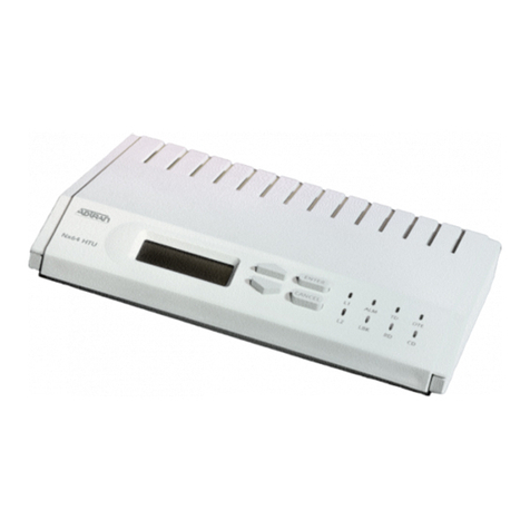
The ADTRAN DDS Type 200 Dual Slot Housing is
used to house one or two standard T200 circuit
packs, and is capable of performing loop
termination. Figure 1 is an illustration of the unit.
Basic Features
The basic features of the unit are listed below.
• Standalone Type 200 housing
• -48VDC power connections
• Network connection through a terminal
barrier strip
• Customer connects to RJ-48S or barrier
strip
• Durable, hinged metal enclosure
• Wraparound transparent front panel for easy
LED viewing
The DDS T200 Dual Slot Housing is designed to
accept any standard Type 200 plug-in card. For
non-loop powered units, the DDS T200 Dual Slot
Housing can provide power to the circuit card
through an external power supply. The ADTRAN
1353.DSK48V02 power supply can be used to
provide -48 VDC from standard 100-120 VAC to
power these cards.
The ADTRAN 1353.POWER08 supply can be used
to provide -48 VDC from standard 220 VAC. These
power supplies must be purchased separately. The
T200 Housing also provides network and customer
interface connections to the circuit card.
Revision History
This is the third release of this document. This
practice has been reissued to include
Telecommunication Configuration Codes and
methods for locally powering the unit.
2. PHYSICAL DESCRIPTION
Figure 1 illustrates the ADTRAN DDS T200 Dual
Slot Housing with the cover on. Connections are
made available by unscrewing the lock screw and
lifting the hinged cover.
Inside the housing are Euro-style connectors,
illustrated in Figure 2, for connecting to the
network, to the CPE, and to an external power
Figure 1. ADTRAN DDS T200 Dual Slot Housing
TOP SLOT - CIRCUIT 2
BOTTOM SLOT - CIRCUIT 1
TR DDS2
PART NUMBER
1212008
Trademarks: Any brand names and product names included in this document are
trademarks, registered trademarks, or trade names of their respective holders.
2 61212008L1-5C, Issue 3 61212008L1-5C
source, if one is used. A grounding lug is provided
for frame ground connections.
The rear panel of the T200 Dual Slot Housing
contains two slots with RJ-48S jacks for CPE
connections and a portal for network and power
connections, illustrated in Figure 3.
The T200 Dual Slot Housing is 2 inches high by 6
inches wide by 9 3/4inches deep, and weighs less
than 1␣ pound. It can be mounted on a desk, table, or
wall. The unit operating temperature range is -40°C
to +70°C.
3. INSTALLATION
After unpacking the unit, immediately inspect it for
possible shipping damage. If damage is discovered,
file a claim immediately with the carrier, then
contact ADTRAN Customer Service. (Refer to
subsection 7, Warranty and Customer Service.)
Components shipped with the unit include the
following:
• T200 chassis (including RJ-48S jack)
• Four #8 screws
• Wall mounting template
The T200 chassis is designed to be wall- or
desk-mounted. For wall mounting, four #8 screws
have been included. Select a suitable position on a
wall or desk for installation.
Figure 4 illustrates the mounting pattern in the base
of the chassis. The four mounting screws should be
located as shown. Drive the screws into the
mounting surface, leaving a clearance of at least
1/4␣ inch, and no greater than 1/2inch.
A mounting template is provided with each unit to
assist in locating the drill holes. The template
attaches to the wall by a tape strip located across the
top of the template. Remove the template from the
wall after using.
Grounding Instructions (UL 1950)
In accordance with UL 1950, a supplemental earth
ground must be connected prior to connection of the
telecommunication wiring. The supplemental earth
ground connection shall be connected to the ground
lug.
Grounding instruction information from the
Underwriter’s Laboratory UL 1950 Standard for
Figure 3. T200 housing Rear Panel
CUSTOMER
CIRCUIT 1 CUSTOMER
CIRCUIT 2
NETWORK
R1 LOOP 1 TX T
TX R
RX T1
RX R1
K1K2
TX T
TX R
RX T1
RX R1
-48V
GND
T1 LOOP 1
R LOOP 2
T LOOP 2
P1
Q1
R1 LOOP 1
T1 LOOP 1
R LOOP 2
R1
D2
R2
TS2
TS4
R3
T LOOP 2
CIRCUIT 2CIRCUIT 1
CUSTOMER
CIRCUIT 1CIRCUIT 2
D1 J2 20
19
Ckt 1 Ckt 2
Figure 2. T200 Housing Terminal Barrier Block
61212008L1-5C 61212008L1-5C, Issue 3 3
Safety (Telephone Equipment) is provided in the
following paragraphs.
In addition to the power supply grounding
conductor, an equipment supplementary grounding
conductor that is not smaller in size than the power
supply grounding conductors, must be installed
prior to connection of telecommunications wiring.
In addition, the connection to the ground of the
supplementary equipment grounding conductors
shall be in compliance with the rules for terminating
bonding jumpers in Part K of Article 250 of the
National Electrical Code ANSI/NFPA 70.
Termination of the supplementary equipment
grounding conductor is permitted to be made to
building steel, to a metal electrical raceway system,
or to any grounded item that is permanently and
reliably connected to the electrical service
equipment ground.
The attachment plug receptacles in the vicinity of
the product or system are all to be of a grounding
type, and the equipment grounding conductors
serving these receptacles are to be connected to
earth ground at the service equipment.
Bare, covered, or insulated grounding conductors
are acceptable. A covered or insulated grounding
conductor shall have a continuous outer finish that is
either green, or green with one or more yellow
stripes.
4. CONNECTIONS
The terminal barrier strip is used to make
connections to the housing. To connect to the
barrier strip, place conductor into the receptacle of
each terminal. The terminal strip is connected to the
card edge connector to interface the connections to
the circuit card. Figure 2 illustrates the pinout of the
card edge connector in relationship to the barrier
strip. The RJ-48 jack, along with the terminal strip,
provides for CPE connection. Table 1 shows the
wiring connections. Table 2 shows the
Telecommunication Configuration Codes.
Power
The T200 Dual Slot Housing is designed to house a
loop-powered or locally-powered circuit card. The
terminal barrier strip provides the ability to connect
an external -48 VDC supply to the circuit card. One
of the following methods shall be utilized when
locally powering the unit:
6"
3"
9.375"
4.5"
7.5"
1.5"
4.5"
Figure 4. Chassis Mounting Template
SDD LANGIS -ORUE ROTCENNOC
002T NIP REBMUN
krowteN
TTRT *TR *RR
2pooLT 2pooLR 1pooL1T 1pooL1R
1474
7
31
remotsuC
TTD RTD TRD RRD
TXT RXT 1TXR 1RXR
5594
5
51
hcaeRlatoTnidesutoN*
MT
.snoitacilppa
Table 1. Wiring Connections
Code Input Output
IC E -
TC X X
PC F C
Table 2. Telecommunication Configuration
Codes
4 61212008L1-5C, Issue 3 61212008L1-5C
• Connect to a reliably grounded -48 VDC
source which is electrically isolated from
the AC source.
• A readily accessible disconnect device, that
is suitably approved and rated, shall be
incorporated in the fixed wiring.
• The branch circuit overcurrent protection
shall be a fuse or circuit breaker rated
minimum 48 V, maximum 20 A.
• The unit shall be installed in accordance
with the requirements of NEC NFPA 70.
OR
• Connect to a Class 2 Type power supply
rated 48 VDC, maximum 240 VA.
These connections are made to the -48V and GND
on the barrier strip, as illustrated in Figure 2.
Connection from the barrier strip to the edge card
connector is illustrated in Figure 2. A ground lug
(P1), illustrated in Figure 2, is provided to connect
an external frame ground wire to the unit.
5. SPECIFICATIONS
The specifications for the ADTRAN T200 Dual Slot
Housing are listed in Table 3.
6. MAINTENANCE
The ADTRAN T200 Dual Slot Housing requires no
routing maintenance to operate properly. In case of
equipment failure, remove the unit and replace it
with another unit optioned in an identical manner.
ADTRAN does not recommend that repairs be
performed in the field. Repair services may be
obtained by returning the defective unit to
ADTRAN.
7. WARRANTY AND CUSTOMER SERVICE
ADTRAN will replace or repair this product within
10 years from the date of shipment if it does not
meet its published specifications or fails while in
service (see ADTRAN Carrier Network Equipment
Warranty, Repair, and Return Policy and Procedure,
document 60000087-10A).
Mechanical
Size ....................................... 6" wide by 9 3/4" deep by 2"
high
Weight .................................. Less than 1 lb.
Mounting .............................. Tabletop or wall-mount
Environment
Temperature ......................... Operating: -40°C to +70°C
Storage: -40°C to +85°C
Relative Humidity ................ Up to 95% non-condensing
Table 3. Specifications
Contact Customer and Product Service (CAPS)
prior to returning equipment to ADTRAN.
For service, CAPS requests, or further information,
contact one of the following numbers:
ADTRAN Sales
Pricing and availability
(800) 827-0807
ADTRAN Technical Support
Presales Applications / Post-sale Technical
Assistance
(800) 726-8663
Standard support hours:
Monday-Friday, 7 a.m. - 7 p.m. CST
Emergency support: 7 days/week, 24 hours/day
ADTRAN Repair/CAPS
Return for repair / upgrade
(256) 963-8722
Repair and Return Address:
ADTRAN, Inc.
Customer and Product Support (CAPS)
901 Explorer Boulevard
Huntsville, Alabama 35806-2807

Other ADTRAN Network Hardware manuals

ADTRAN T200 H2TU-R Instruction Manual

ADTRAN

ADTRAN T200 H2TU-R Instruction Manual

ADTRAN HDSL4 User manual

ADTRAN

ADTRAN HDSL4 User manual

ADTRAN IQ 310 User manual

ADTRAN

ADTRAN IQ 310 User manual

ADTRAN CenturyLink C424G User manual

ADTRAN

ADTRAN CenturyLink C424G User manual

ADTRAN 401 1 GE Micro ONT User manual

ADTRAN

ADTRAN 401 1 GE Micro ONT User manual

ADTRAN ATLAS 810 Plus User manual

ADTRAN

ADTRAN ATLAS 810 Plus User manual

ADTRAN D4 TRI-C DP User manual

ADTRAN

ADTRAN D4 TRI-C DP User manual

ADTRAN T1 Nx64 HTU-R Instruction Manual

ADTRAN

ADTRAN T1 Nx64 HTU-R Instruction Manual

ADTRAN NetVanta 818 User manual

ADTRAN

ADTRAN NetVanta 818 User manual

ADTRAN Total Access 300 Instruction Manual

ADTRAN

ADTRAN Total Access 300 Instruction Manual

ADTRAN DS3 NIU3 User manual

ADTRAN

ADTRAN DS3 NIU3 User manual

ADTRAN HD-10 BRI MUX Instruction Manual

ADTRAN

ADTRAN HD-10 BRI MUX Instruction Manual

ADTRAN 1442940G1 User manual

ADTRAN

ADTRAN 1442940G1 User manual

ADTRAN Total Access 1248 User manual

ADTRAN

ADTRAN Total Access 1248 User manual

ADTRAN DSX 1 User manual

ADTRAN

ADTRAN DSX 1 User manual

ADTRAN 1442351G7 User manual

ADTRAN

ADTRAN 1442351G7 User manual

ADTRAN DSU III TDM User manual

ADTRAN

ADTRAN DSU III TDM User manual

ADTRAN Total Access 324E User manual

ADTRAN

ADTRAN Total Access 324E User manual

ADTRAN SHDSL T1 Instruction Manual

ADTRAN

ADTRAN SHDSL T1 Instruction Manual

ADTRAN NetVanta 2000 Series User manual

ADTRAN

ADTRAN NetVanta 2000 Series User manual

ADTRAN NetVanta 6360 User manual

ADTRAN

ADTRAN NetVanta 6360 User manual

ADTRAN DSX 1 User manual

ADTRAN

ADTRAN DSX 1 User manual

ADTRAN NxT1 HSSI/V-35 User manual

ADTRAN

ADTRAN NxT1 HSSI/V-35 User manual

ADTRAN GPON TA352 User manual

ADTRAN

ADTRAN GPON TA352 User manual

Popular Network Hardware manuals by other brands

Zhone 4929 4929-A1-520 Specification sheet

Zhone

Zhone 4929 4929-A1-520 Specification sheet

WEISS DAC502 quick start guide

WEISS

WEISS DAC502 quick start guide

MikroTik nRAY Series quick guide

MikroTik

MikroTik nRAY Series quick guide

Cisco IPS-4260-K9 - IPS Sensor 4260 Installation

Cisco

Cisco IPS-4260-K9 - IPS Sensor 4260 Installation

ClearView PhoenixView 04B-04IP94 user manual

ClearView

ClearView PhoenixView 04B-04IP94 user manual

Altronix Trove Plus T2M7LCK1 installation guide

Altronix

Altronix Trove Plus T2M7LCK1 installation guide

General DataComm SC-ADT 8 Port Installation & operation manual

General DataComm

General DataComm SC-ADT 8 Port Installation & operation manual

Ruckus Wireless ZoneFlex P300 Quick setup guide

Ruckus Wireless

Ruckus Wireless ZoneFlex P300 Quick setup guide

Positron 751366 Description and installation

Positron

Positron 751366 Description and installation

Dveo OnRamp/IP quick start guide

Dveo

Dveo OnRamp/IP quick start guide

Bustec ProDAQ 3202 installation instructions

Bustec

Bustec ProDAQ 3202 installation instructions

Qvis CORTEX Installer's quick setup guide

Qvis

Qvis CORTEX Installer's quick setup guide

Leroy-Somer R220 VSG Installation and Maintenance

Leroy-Somer

Leroy-Somer R220 VSG Installation and Maintenance

ADC HiGain HDSL2 Quick installation guide

ADC

ADC HiGain HDSL2 Quick installation guide

ADC HRE-425 List 1 user manual

ADC

ADC HRE-425 List 1 user manual

Cisco 5500 Series Guide

Cisco

Cisco 5500 Series Guide

Alacritech SEN1811XT Hardware installation guide

Alacritech

Alacritech SEN1811XT Hardware installation guide

Fortinet FortiGate 80F Series quick start guide

Fortinet

Fortinet FortiGate 80F Series quick start guide

manuals.online logo
manuals.online logoBrands
  • About & Mission
  • Contact us
  • Privacy Policy
  • Terms and Conditions

Copyright 2025 Manuals.Online. All Rights Reserved.