manuals.online logo
Brands
  1. Home
  2. •
  3. Brands
  4. •
  5. ADTRAN
  6. •
  7. Network Hardware
  8. •
  9. ADTRAN HTU-C User manual

ADTRAN HTU-C User manual

C A U T I O N !
SUBJECT TO ELECTROSTATIC DAMAGE
OR DECREASE IN RELIABILITY.
HANDLING PRECAUTIONS REQUIRED.
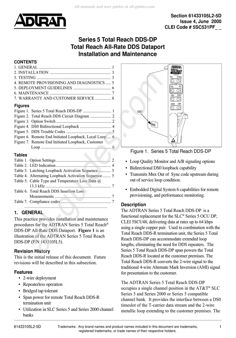
For more information, refer to the Installation and Maintenance Practice (P/N 61247002L1-5) available online at www.adtran.com.
©2007 ADTRAN, Inc.
All Rights Reserved.
HDSL
HTU-CNB/WB
for Litespan
P/N: 1247002L1
CLEI: SLL7AAAA_ _
*61247002L1-22A*
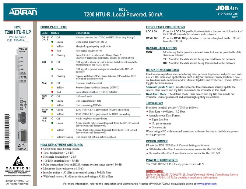
HDSL DEPLOYMENT GUIDELINES
♦Cable Pairs must be non-loaded
♦Total Bridged Tap < 2.5 kft
♦No single Bridged Tap > 2 kft
♦196 kHz insertion loss ≤35 dB
♦Pulse attenuation (loss on HDSL current system status screen) ≤30 dB
♦Maximum loop resistance is 800 Ω
♦Impulse noise ≤50 dBrn as measured using a 50 kb filter
♦Wideband noise ≤31 dBrn as measured using a 50 kb filter
CAUTION: If the L1 is used in applications where narrowband and wideband copper
service wire pairs are connected simultaneously, only one service pair can
have terminating equipment connected to the HTU-C. Also, copper
service wire pairs not in use are considered bridged tap to the HDSL
loops in service and should be considered in the deployment guidelines. If
the bridged tap presented by the unused loop violates the CSA guidelines,
the unused pair should be disconnected.
PROVISIONING OPTIONS
1. When set for FT1, the CLOS setting is ignored. System will send an FT1 idle signal from
the HTU-C NB/WB for Litespan to the network consisting of a repeating 7E byte payload.
2. This option is not available if the HTU-R P/N 1247026L7 is used in the circuit.
3. This option is only available if the HTU-R P/N 1247026L4 is used in the circuit.
4. This option is not available if the HTU-R P/N 1247026L6 is used in the circuit.
COMPLIANCE
Refer to the HDSL HTU-C using Narrowband / Wideband for Litespan Compliance
Notice (P/N 61247002L1-17) for detailed compliance information.
Provisioning Option Option Setting Default Settings
Line Code B8ZS; AMI B8ZS
Framing AUTO; ESF; SF; UNF; FFFC AUTO
Loopback Timeout None; 60 minutes; 120 minutes 120 minutes
DS1 Transmit level 0dB; –15 dB 0 dB
Span Power Enabled; Disabled Enabled
DS1 Latching Loopback (1) T1; FT1 T1
Customer Loss Response AIS; LPBK; CDI AIS
NIU Loopback (2) Enabled; Disabled Enabled
New England Loopback (3) Enabled; Disabled Disabled
PRM Setting (4) None; SPRM; NPRM None
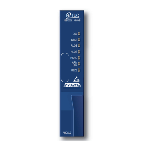
Front Panel LEDs
RS-232 DB-9 CONNECTOR
Used to access performance monitoring data, perform loopbacks, and provision units
via VT 100 emulation applications, such as HyperTerminal–Private Edition. There
are two terminal emulation modes: Manual Update and Real-Time Update. CTRL+T
toggles between modes.
Manual Update Mode
Press the spacebar three times to manually update the screen. Print screen and log
files commands are available in this mode.
Real-Time Mode
The default mode. Print screen and log file commands not available. Cursor
placement and screen highlighting are enabled. Provision the terminal port for
VT100 as follows:
♦Data Rate of 1.2 kbps to 19.2 kbps
♦Asynchronous Data Format:
♦Eight data bits
♦No parity (none)
♦One stop bit
NOTE: When using a PC with terminal emulation software, be sure to disable any
power saving programs.
INSTALLATION
After unpacking the unit, inspect it for damage. If damage is noted, file a claim with
the carrier and then contact ADTRAN. For more information, refer to the Warranty.
Label Status Description
LOOP {
z
2
Off
Green
Green Flashing
Unit is not in armed or loopback state.
A loopback is active on this unit.
Unit is in an armed state but not in loopback.
FAIL {
z
Off
Red
Unit is initialized and working properly.
Initializing or unable to operate.
HDSL z
z
Yellow
Red
Both loops are synchronized, but there is a yellow or red
alarm at the DS1 interface.
One or both loops are out of synchronization.
LP1 /LP2 {
z
z
z
5
Off
Green
Yellow
Red
Flashing
No synchronization between HTU-C and HTU-R on
loop 1/ loop 2.
Good signal quality on loop 1/ loop 2.
Marginal signal quality on loop 1/ loop 2.
Severely impaired signal quality on loop 1/ loop 2.
Error detected on either end of loop 1/ loop 2.
61247002L1-22A
0708
HDSL
HTU-C using Narrowband / Wideband for Litespan®
PRICING AND AVAILABILITY 800.827.0807
TECH SUPPORT 800.726.8663
RETURN FOR REPAIR 256.963.8722
www.adtran.com
61247002L1-22A
Warranty: ADTRAN will replace or repair this product within the warranty period if it does not meet its published specifications or fails while in service.
Warranty information can be found online at www.adtran.com/warranty.
TROUBLESHOOTING GUIDE
Condition Solution
At Power-Up, all Front Panel
Indicators are Off.
1. Verify that the channel bank or ONU BPS power LEDs are on.
2. Make sure that the unit is fully and correctly inserted into the channel bank
or ONU.
3. If step 1 fails, contact Alcatel customer service. If step 1 passes, but step 2
fails, replace the HTU-C NB/WB for Litespan.
The HTU-R has Power, but
LP1 or LP2 LEDs are Dark.
The Unit cannot Sync with the
HTU-C NB/WB for Litespan.
1. Simplex power for the powering for the HTU-R can be passed over cable
pairs that contain load coils or that are too long for HDSL synchronization.
Using a TIMS, verify that the circuit is within design limits.
2. The HTU-R powers-up as long as there is at least one good conductor on
each loop. To test, remove the protectors from the MDF and measure
t-r resistance to the HTU-R on both loops. The HTU-R places a 3 ohm
short between t-r on both loops. An extremely high impedance indicates an
open conductor. An extremely low reading on one loop may indicate a t-r
short in the field. In the field, measure t-t and r-r voltage with the HTU-C
NB/WB for Litespan installed. If these voltages are not present, open pairs
or mis-wiring is indicated. As with other circuits, standard resistance
measurements between each conductor and ground should also be used to
test for a grounded conductor.
3. A high-resistance open which degrades to the point that it causes the circuit
to lose sync can be “resealed” by reseating the HTU-C NB/WB for
Litespan. Test the cable pairs before reseating the HTU-C NB/WB for
Litespan.
The FAIL LED Remains On. 1. Verify that the channel bank or ONU BPS FAIL LEDs are off.
2. Verify that the equipment type for the HTU-C NB/WB for Litespan slot is
AHT1U. Using TL1, equipment type is shown with the command
rtrv-eqpt; AID, where AID is the access identifier (i.e., cot-1-15).
3. If step 1 fails, contact Alcatel customer service. If step 1 and step 2 pass,
replace the HTU-C NB/WB for Litespan. If step 1 passes but step 2 fails,
delete the equipment record (i.e., dlt-eqpt; cot-1-15 with TL1) and reinsert
the card, or equip the slot with the currently reserved equipment type.
The HTU-Rs DS1 LED is
Flashing, but No Errors are
Indicated by the HTU-C NB/
WB for Litespan.
A BPV, Frame Error (SF), or CRC Error (ESF) has been detected at the DS1
input. This indicates a wiring problem or a B8ZS/AMI mismatch between the
HTU-R and the CPE equipment. This is not an indication of problems on the
HDSL loops.
The FAIL LED is Off, but the
HDSL LED Remains Red.
1. Check that neither HDSL loop is open.
2. Check that neither or both HDSL loops are shorted.
3. Verify the loop conforms to CSA guidelines and is not too long. Loop loss
at 200 kHz should be less than 35.25 dB.
4. Verify that both HDSL loops have acceptable noise limits.
5. Verify that tip and ring of each HDSL loop belongs to the same twisted
pair.
6. If steps 1 through 5 pass, but the HDSL LED remains red, replace the
HTU-C.
7. If step 6 fails, replace the HTU-R and the HRE.
* This option is only applicable for software release 7.1.6 and lower.
TURN-UP GUIDE
1. Equip the COT slot for the ADS1U and the RT slot for the HTU-C NB/WB for Litespan.
2. Install the ADSIU in the COT, HTU-C NB/WB for Litespan in the RT, and the HTU-R at the
customer premises.
3. Make the cross connects between the ADSIU and the HTU-C NB/WB for Litespan.
4. Ensure that the (HTU-C NB/WB for Litespan) LEDs are as follows:
♦LOOP {Off
♦FAIL {Off
♦HDSL {Off
♦LP1 / LP2 zGreen
5. Provision the cards according to the circuit design and specifications.
6. Perform BERT testing.
NOTE: The HTU-C NB/WB for Litespan puts out –137 volts span power. It is capable of powering one
repeater and a remote unit.
The FAIL LED is Off, but the
HDSL LED Remains Yellow.
1. Check that the framing and line coding are set appropriately for T1 data at
the HTU-R and for cross-connect T1 data coming to the HTU-C NB/WB
for Litespan.
2. Check that the DS1 LED at the HTU-R is green.
3. If step 1 fails, change the appropriate framing and line coding. If step 1
passes, but step 2 fails, a problem may exist at the HTU-R T1 interface. If
the problem does not exist at the T1 interface, Replace the HTU-C NB/WB
for Litespan.
HDSL LED Yellow, HTU-R
DS1 LED Red (Customer Loss
of Signal).
To prevent major alarms from being reported in the central office, set the CLOS
option to LPBK or CDI.*
Running Excessive Errors on
the Loop.
1. Measure t-r resistance as described above. If the pairs are unbalanced by
more than 4 ohms, or a measurement varies a great deal, this could indicate
a high resistance open or an intermittent fault on the loop with the higher
measurement. A TDR is typically required to locate this splice for
correction.
2. Excessively long bridged taps can also cause errors. Check the records
and/or use a TDR to verify the location and length of bridged taps.
3. Using ADTRAN’s “Performance History” screen, it is often possible to see
that many more errors are being received on a particular loop or at a
particular unit. The fault is typically very close to the unit receiving the
most errors.
Condition Solution
HDSL
HTU-C using Narrowband / Wideband for Litespan®

Other ADTRAN Network Hardware manuals

ADTRAN DSU IV ESP User manual

ADTRAN

ADTRAN DSU IV ESP User manual

ADTRAN D4 FT1 DP User manual

ADTRAN

ADTRAN D4 FT1 DP User manual

ADTRAN T1 CSU ACE User manual

ADTRAN

ADTRAN T1 CSU ACE User manual

ADTRAN T1 Nx64 HTU-R Instruction Manual

ADTRAN

ADTRAN T1 Nx64 HTU-R Instruction Manual

ADTRAN DS3 NIU3 PM Instruction Manual

ADTRAN

ADTRAN DS3 NIU3 PM Instruction Manual

ADTRAN NetVanta 5660 User manual

ADTRAN

ADTRAN NetVanta 5660 User manual

ADTRAN ACT 1900 User manual

ADTRAN

ADTRAN ACT 1900 User manual

ADTRAN Total Access 300 Series User manual

ADTRAN

ADTRAN Total Access 300 Series User manual

ADTRAN ISU 512 User manual

ADTRAN

ADTRAN ISU 512 User manual

ADTRAN Dial Backup Interface Module 1204006L2 User manual

ADTRAN

ADTRAN Dial Backup Interface Module 1204006L2 User manual

ADTRAN BR1 User manual

ADTRAN

ADTRAN BR1 User manual

ADTRAN NetVanta 2000 Series User manual

ADTRAN

ADTRAN NetVanta 2000 Series User manual

ADTRAN JOBAID Total Access 838 User manual

ADTRAN

ADTRAN JOBAID Total Access 838 User manual

ADTRAN Total Access 1100F User manual

ADTRAN

ADTRAN Total Access 1100F User manual

ADTRAN ISU 512E User manual

ADTRAN

ADTRAN ISU 512E User manual

ADTRAN NetVanta 838 User manual

ADTRAN

ADTRAN NetVanta 838 User manual

ADTRAN 1442703PG2 User manual

ADTRAN

ADTRAN 1442703PG2 User manual

ADTRAN Dual Nx56/64 User manual

ADTRAN

ADTRAN Dual Nx56/64 User manual

ADTRAN NetVanta 1000 Series Manual

ADTRAN

ADTRAN NetVanta 1000 Series Manual

ADTRAN SLC-5 U-BR1TE III Instruction Manual

ADTRAN

ADTRAN SLC-5 U-BR1TE III Instruction Manual

ADTRAN NetVanta 1531 Series Manual

ADTRAN

ADTRAN NetVanta 1531 Series Manual

ADTRAN TSU 100 User manual

ADTRAN

ADTRAN TSU 100 User manual

ADTRAN 1200184L1 User manual

ADTRAN

ADTRAN 1200184L1 User manual

ADTRAN NetVanta 2000 Series User manual

ADTRAN

ADTRAN NetVanta 2000 Series User manual

Popular Network Hardware manuals by other brands

Bosch D8125INV Operation and installation guide

Bosch

Bosch D8125INV Operation and installation guide

ACTi GNR -3000 user manual

ACTi

ACTi GNR -3000 user manual

Cabletron Systems DLE52-MA user guide

Cabletron Systems

Cabletron Systems DLE52-MA user guide

BuildingLink KeyLink 140 PRODUCT SPECIFICATIONS & SETUP GUIDE

BuildingLink

BuildingLink KeyLink 140 PRODUCT SPECIFICATIONS & SETUP GUIDE

pivotal COMMWARE ECHO 5G How to set up

pivotal

pivotal COMMWARE ECHO 5G How to set up

VC 16835 Mounting and operating manual

VC

VC 16835 Mounting and operating manual

Barefoot nbn HFC Connection guide

Barefoot

Barefoot nbn HFC Connection guide

Juniper JATP700 Hardware guide

Juniper

Juniper JATP700 Hardware guide

Adva FSP 3000R7 Maintenance and troubleshooting manual

Adva

Adva FSP 3000R7 Maintenance and troubleshooting manual

ZyXEL Communications NSA-220 Plus user guide

ZyXEL Communications

ZyXEL Communications NSA-220 Plus user guide

Hoymiles DTU-Lite-S(Wi-Fi) Quick installation guide

Hoymiles

Hoymiles DTU-Lite-S(Wi-Fi) Quick installation guide

NETGEAR ReadyDATA 5200 installation guide

NETGEAR

NETGEAR ReadyDATA 5200 installation guide

Enterasys 6E2xx Local Management User’s Guide

Enterasys

Enterasys 6E2xx Local Management User’s Guide

Canon Vb-C60 - Ptz Network Camera Operation guide

Canon

Canon Vb-C60 - Ptz Network Camera Operation guide

LAPP ETHERLINE GUARD PM03T operating instructions

LAPP

LAPP ETHERLINE GUARD PM03T operating instructions

Gigamon GigaVUE H Series Hardware installation guide

Gigamon

Gigamon GigaVUE H Series Hardware installation guide

SonicWALL TELE3 TZ Getting started guide

SonicWALL

SonicWALL TELE3 TZ Getting started guide

AK-NORD COMPOINT-LIB manual

AK-NORD

AK-NORD COMPOINT-LIB manual

manuals.online logo
manuals.online logoBrands
  • About & Mission
  • Contact us
  • Privacy Policy
  • Terms and Conditions

Copyright 2025 Manuals.Online. All Rights Reserved.