2 Section 61107005L2-5, Issue 3 61107.005L2-5C
In the DDS system, an OCU DP located at an end office
interfacesthecustomer totheTcarrier system. A4-wire
loop is terminated at the customer premises by a data
serviceunit(DSU)orachannelserviceunit(CSU).Itcan
be used in the hub office, intermediate office, end office,
orSLC®terminaltoextendtheDDSnetworktothatoffice
whichhaspreviously servedvoicechannelsexclusively.
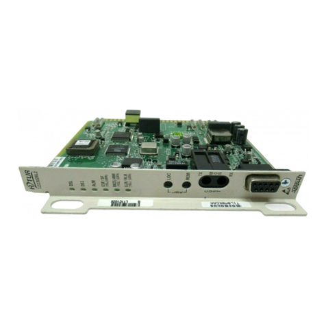
The ADTRAN All-Rate Extended Range D4-OCU DP is
interchangeable with the following AT&T units:
• Subrate OCU DP (J98726DB)
• 56 kbps OCU DP (J98726DE)
• All Rate OCU DP (J98726DJ)
The unit is also interchangeable with all previous and
current ADTRAN units including the following:
• All-Rate OCU DP (1102005A)
• All-Rate with 38.4/64 kbps OCU DP (1102006A)
• All-Rate OCU DP (1104005L9)
2. INSTALLATION
After unpacking the unit, immediately inspect it for
possibleshippingdamage. Ifdamageisdiscovered,file
aclaimimmediatelywiththecarrierandcontactADTRAN
Customer Service (see subsection 7).
The D4-OCU DP plugs directly into a WECO®, or
equivalent,D4channelbank, ADTRANGeneralPurpose
Communication (GPC) shelves, or ADTRAN ACT-1241
channel bank. No installation wiring is required.
A sixteen-position rotary switch on the faceplate and an
internalten-positionslideswitch(SW1)mustbesetprior
to installing the unit.
Sixteen-Position Rotary Faceplate Switch
The settings for the sixteen-position rotary switch select
loop rates of 2.4, 4.8, 9.6,19.2, 38.4, 56, SW56, or 64
kbps,andSecondaryChannel(SC). Settheswitchfunctions
as illustrated in Figure 2.
When 64 kbps is selected, normal loopbacks
are automatically disabled. Only latching
loopbackmaybeusedat thisrate.WhenSW56
is selected as the operating rate, SW1-1 must
remain off.
________________________________________
SLC is a registered trademark of AT&T
WECO is a registered trademark of AT&T
Internal Switch Option Settings
The location of the ten-position slide switch is illustrated
in Figure 3. The option settings are provided in Table B.
SW1 is a ten-position slide switch which enables or
disables error correction, bank type, zero code
suppression,latching loopback,hardwareA/B signaling,
quality monitoring, and extended transmit range.
If more than one bank type is selected (on), the OCU DP
will not function.
There are restrictions in the deployment of
38.4, 56, and 64 kbps with error correction in
aD4bank.Whenthedataportisconfiguredfor
no error correction, a single timeslot is used
andtheunitmaybelocatedinanychannelslot
oftheD4bank.With38.4,56and64kbpserror
correction selected, the dataport generates a
parity byte for each data byte, thus occupying
twotimeslots. If thestandardD4 38.4,56 and
64kbpserrorcorrectionoptionisselected,the
parity byte is inserted into the timeslot
immediately following the data. The specific
designoftheD4commonequipmentinteracts
with the error correcting schemes and yields
the following deployment restrictions on a
38.4, 56 and 64 kbps dataport with error
correction:
a. All D4 Modes: Dataport may not be located
in channel slot 24.
b. D4 Modes 1, 2: Data and parity must be
confinedto groupsof sixchannelslots(i.e.,
slots 1-6, 7-12, 13-18, or 19-24.)
Figure 2. Rate Option Switch
Shown with 9.6 kbps Secondary Channel
selected. Two positions do not have rates
associatedwiththem. TheD4-OCUDPwillnot
function when these switch positions are set.
9.6
9.6
19.2
19.2
38.4
38.4
56 56
64
4.8
4.8
2.4
2.4
SW56
SC
No rate selection
No rate selection
