manuals.online logo
Brands
  1. Home
  2. •
  3. Brands
  4. •
  5. ADTRAN
  6. •
  7. Transceiver
  8. •
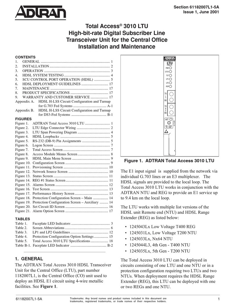
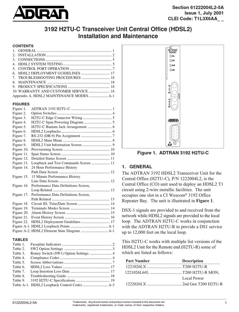
  9. ADTRAN T200 H2TU-R User manual

ADTRAN T200 H2TU-R User manual

C A U T I O N !
SUBJECT TO ELECTROSTATIC DAMAGE
OR DECREASE IN RELIABILITY.
HANDLING PRECAUTIONS REQUIRED.
A complete Installation and Maintenance Practice (P/N 61223HDSL2L2-5) can be found at www.adtran.com. Enter the desired P/N in the search field.
HDSL2
T200 H2TU-R
P/N 1223026L2
CLEI: T1L8MOKC_ _
T200 HDSL2 Remote Transceiver Unit, Span Powered
TX
RX
REM
LOC
L
B
K
1223026L2
DSL
DS1
ALM
(GRN)
SF
(YEL)
ESF/
(GRN)
AMI
(YEL)
B8ZS
/
(GRN)
RLB
(YEL)
LLB
/
URH T
C
U
S
R
S
2
3
2
T
M
O
N
*61223026L2-22B*
CARD EDGE PINOUTS
RS-232 DB-9 CONNECTOR
Used to access performance monitoring data, perform loopbacks, and provision units
via VT100 emulation applications, such as HyperTerminal - Private Edition.
♦There are two types of terminal emulation modes:
♦Manual Emulation Mode: Press the space bar three times to manually update the
screen. Print Screen and Log File commands are available in this mode.
♦Real-Time Emulation Mode: The default mode. Print Screen and Log File
commands are not available in this mode. Cursor placement and screen
highlighting are enabled.
Use CTRL+T to toggle between the two terminal emulation modes.
♦Provision terminal port for VT100 as follows:
♦Data Rate: 1.2 to 19.2 kbps
♦Asynchronous Data Format: Eight data bits, no parity (none), one stop bit
♦When using a PC with terminal software, disable any power saving programs.
COMPLIANCE
WARNING: Up to –200 VDC may be present on telecommunications wiring.
This product is intended to be installed in Restricted Access Areas only and in
equipment with a Type “B” or “E” enclosure.
This product meets all requirements of Bellcore GR-1089-CORE (Class A2) and
ANSI T1.418-2002, and is NRTL listed to the applicable UL standards.
Pin Designation Description
1CH GND Chassis ground
5DS1-T1 DS1 receive out tip (to customer interface)
7H1-T HDSL2 Loop tip (facility)
11 CH GND Chassis ground
12 GND Ground for protection switching
13 H1-R HDSL2 Loop ring (facility)
15 DS1-R1 DS1 receive out ring (to customer interface)
20 VCC +5 VDC for protection switching
27 CH GND Chassis ground
40 PROT-1 Control line for protection switching
49 DS1-R DS1 transmit in ring (from customer interface)
55 DS1-T DS1 transmit in tip (from customer interface)
Code Input Output
Power Code C C
Telecommunication Code (TC) X X
Installation Code (IC) A –
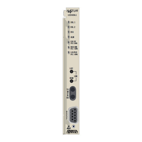
LED STATUS
PUSHBUTTON LOOPBACK FUNCTIONS
♦LOC - Initiates a bidirectional loopback of the H2TU-R toward the network and
customer
♦REM - Initiates a bidirectional loopback at the H2TU-C toward the network and
customer
DS1 BRIDGING (BANTAM) JACKS
If the DS1 test set is optioned for MONITOR, the monitor jacks provide a nonintrusive
tap onto the signal line.
♦TX - Monitors the data stream being received from the customer equipment
♦RX - Monitors the data stream being transmitted to the customer equipment
POWERING MODES
This T200 H2TU-R is span powered only. If a locally powered H2TU-R is required,
order P/N 1223024L2.
Label Status Description
DSL !Green
!Red
!Flashing
Good signal margin on the loop (> 2 dB margin above 10−7
BER)
Poor signal margin on the loop (≥ 10−7 BER)
Error detected at H2TU-C or H2TU-R (the color of this LED
will match the color representing the signal margin of the
loop)
DS1 !Green
!Red
Customer-side DS1 signal is present and synchronized
Customer-side DS1 signal not detected from customer or is
of a format not matching the HDSL2 circuit provisioning
ALM "Off
!Red
!Yellow
No alarm condition detected
Local alarm condition (H2TU-R) detected
Remote alarm condition (H2TU-C) detected
ESF/SF "Off
!Green
!Yellow
Unit is Provisioned for Unframed operation
Unit is Provisioned for DS1 SF framing mode
Unit is Provisioned for DS1 ESF framing mode
B8ZS/AMI !Green
!Yellow
Unit is Provisioned for AMI coding
Unit is Provisioned for B8ZS coding
LLB/RLB "Off
!Green
!Yellow
Unit is not in loopback or armed state
Active remote bidirectional loopback at the H2TU-C
Unit is in bidirectional loopback at the H2TU-R
61223026L2-22B
0410
PRICING AND AVAILABILITY 800.827.0807
TECH SUPPORT 800.726.8663
RETURN FOR REPAIR 256.963.8722
www.adtran.com
61223026L2-22B
Warranty: ADTRAN will replace or repair this product within the warranty period if it does not meet its published specifications or fails while in service.
Warranty information can be found at www.adtran.com/warranty.
T200 HDSL2 Remote Transceiver Unit, Span Powered
TROUBLESHOOTING HDSL2
This ADTRAN HDSL2 unit is equipped with troubleshooting-at-a-glance LEDs (identified on the reverse side of
this document) that provide customers with a simple means of identifying the location of certain faults.
Additionally, screens available via the craft interface simplify the trouble isolation process. These screens and their
associated benefits are described below.
Troubleshooting Screen
Available via the Main Menu (Option 12) - provides ADTRAN contact information and access to the
Troubleshooting Guidance and General Information screens.
Troubleshooting Guidance Screens
Available via the Troubleshooting screen (Option 1) - detects and displays errors and/or alarms at any of the
monitored inputs (DSX1, DS1 and HDSL). Guidance on the fault(s) detected includes possible cause(s) and
suggested actions, including those shown below:
DSX-1/DS1:
LOS Loss of signal (Red Alarm) at the DSX-1/DS1 receiver
CLK T1 receive clock is out of range
RAI Remote Alarm Indication (Yellow Alarm) detected at DSX-1/DS1 receiver
AIS Alarm Indication Signal (Blue Alarm) detected at DSX-1/DS1 receiver
ERR Errors recorded at DSX-1/DS1 receiver
Facility:
GROUND Ground Fault Interrupt on span voltage (facility pair grounded)
SHORT Short circuit (or low impedance) between facility pairs
OPEN Open circuit between facility pairs
DSL:
LOS Loss of HDSL sync
MARG Margin has exceeded the alarm threshold
ATTEN Attenuation has exceeded the alarm threshold
ERR Errors recorded at the HDSL receiver
HIST Performance History of the DSL units
General Information Screen
Available via the Troubleshooting screen (Option 2) - a reference page which displays the minimum acceptable
signal margin, maximum attenuation, and other deployment parameters for this HDSL2 circuit. A sample display of
this screen is shown below:
HDSL2 Loop Guidelines for optimum operation
-------------------------------------------
Non-loaded cable pair
Single bridge tap < 2 kft
Total bridge taps < 2.5 kft
Bridge tap within 1000 ft of transceiver may affect performance
Impulse noise < 50 dBrnF (F filter)
Wideband noise < 31 dBrnF (F filter)
Power influence ≤80 dBrnC
Longitudinal Balance ≥60 dB (If using Wideband test at 196 Khz ≥40dB)
Foreign DC Voltage (t-r, t-g, r-g) < 3 VDC
Loop Resistance ≤775 ohms
Margin ≥6 dB
Attenuation ≤28 dB
Along with the Troubleshooting screens, the Detailed Status screen and Performance History screen, available via
the craft access terminal, provide both real-time and historical view of this circuit.
FEATURES
TScan
This module is equipped to function with Central Office units (H2TU-C) having the TScan™feature. TScan allows
for remote retrieval of circuit diagnostics and performs advanced fault location. For more information about TScan
refer to the Installation and Maintenance practice.
Bad Splice Detection
The Runtime TScan splice detection feature is an ADTRAN proprietary non-intrusive method for detection of
anomalies (poor splice connections) in the copper plant.
Data transmission transceivers, especially echo-cancelled technologies, such as HDSL2 (or HDSL4) are subject to
degraded performance in the presence of deteriorating splice connections. This deterioration is often undetected by
normal testing methods. Often, these splices present no problem for the data transmission equipment until the point
at which oxidation within the splice itself causes a rapid impedance change. Such a change in impedance may cause
errors, signal margin fluctuation, and/or a retrain of the DSL transceivers. To address the difficulty in identifying
deteriorating splice connections, ADTRAN has developed the splice detection feature, which non-intrusively
monitors the cable pair during runtime for the presence of deterioration.
The screen below, accessed from the troubleshooting screen, shows a suspect splice 250 feet from the H2TU-C.
Fault Bridging
Fault Bridging is a feature that minimizes downtime due to an intermittent impairment (GFI, short, micro-
interruption, bad splice, noise burst, etc.) that appears on the cable pair.
The bridging feature allows the DSL transceivers to maintain synchronization during such an interruption, thus
avoiding a 25 to 30 second retrain. Depending on the type of impairment, interruptions as long in duration as 200 ms
can be bridged.
Fast Retrain
Fast Retrain is an ADTRAN proprietary feature that minimizes downtime due to an intermittent impairment (bad
splice, noise burst, etc.) which due to its duration cannot be bridged.
When such impairments occur after HDSL synchronization has been achieved, the fast retrain feature will be
invoked to restore service within 5 to 7 seconds. This short retrain time allows for reduced downtime compared to
the traditional 25 to 30 second retrain duration.
NOTE: Fast-Retrain capable units must be installed on both ends of the HDSL2 circuit for this feature to
function properly. Also, if there is a failure, for any reason, of a Fast Retrain attempt then the
traditional (25-30 second) retrain will be initiated.
Circuit ID: 06/06/04 09:29:45
Press ESC to return to previous menu
* Note: Chronic Circuit Results are only valid after all other circuit *
* qualification tests have been performed and failed to show a trouble !! *
Splice Detector Version 1 Result Definitions:
---------------------------------------------
NTF - No Trouble Found yet.
LOS - Unit not in sync.
Number - Distance from Reference point (in ft.) of suspect splice.
Reference Splice Detection Version Result Shown
Point Results Number for date
--------- ---------------- ------- MM/DD/YY
H2TUC 250 01 --------
H2TUR NTF -- 06/06/04
(B)Back
Other manuals for T200 H2TU-R

5

This manual suits for next models

1

Other ADTRAN Transceiver manuals

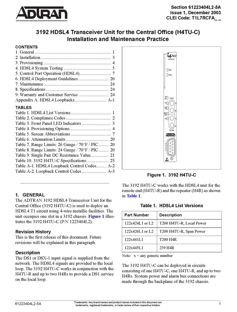
ADTRAN HTU-C NB Instruction Manual

ADTRAN

ADTRAN HTU-C NB Instruction Manual

ADTRAN SFP+ Combo PON D1 OLT User manual

ADTRAN

ADTRAN SFP+ Combo PON D1 OLT User manual

ADTRAN 3192 User manual

ADTRAN

ADTRAN 3192 User manual

ADTRAN 220 HTU-C Instruction Manual

ADTRAN

ADTRAN 220 HTU-C Instruction Manual

ADTRAN 11.3G XFP User manual

ADTRAN

ADTRAN 11.3G XFP User manual

ADTRAN T200 FNID Instruction Manual

ADTRAN

ADTRAN T200 FNID Instruction Manual

ADTRAN HDSL2 DDM+ H2TU-C User manual

ADTRAN

ADTRAN HDSL2 DDM+ H2TU-C User manual

ADTRAN Combo PON D2 SFP+ User manual

ADTRAN

ADTRAN Combo PON D2 SFP+ User manual

ADTRAN DDM Plus HTU-C Instruction Manual

ADTRAN

ADTRAN DDM Plus HTU-C Instruction Manual

ADTRAN 3060 Instruction Manual

ADTRAN

ADTRAN 3060 Instruction Manual

ADTRAN T200 H4TU-R Instruction Manual

ADTRAN

ADTRAN T200 H4TU-R Instruction Manual

ADTRAN QSFP+ User manual

ADTRAN

ADTRAN QSFP+ User manual

ADTRAN QSFP28 100G SR4 User manual

ADTRAN

ADTRAN QSFP28 100G SR4 User manual

ADTRAN 40 G ER4 QSFP+ User manual

ADTRAN

ADTRAN 40 G ER4 QSFP+ User manual

ADTRAN 3192 H4TU-C Instruction Manual

ADTRAN

ADTRAN 3192 H4TU-C Instruction Manual

ADTRAN 1442140G2 User manual

ADTRAN

ADTRAN 1442140G2 User manual

ADTRAN 3192 HDSL4 Instruction Manual

ADTRAN

ADTRAN 3192 HDSL4 Instruction Manual

ADTRAN JOBAid HDSL2 User manual

ADTRAN

ADTRAN JOBAid HDSL2 User manual

ADTRAN HTU-C M Instruction Manual

ADTRAN

ADTRAN HTU-C M Instruction Manual

ADTRAN T200 H4TU-R User manual

ADTRAN

ADTRAN T200 H4TU-R User manual

ADTRAN 3192 H2TU-C Instruction Manual

ADTRAN

ADTRAN 3192 H2TU-C Instruction Manual

ADTRAN 1442482F7 User manual

ADTRAN

ADTRAN 1442482F7 User manual

ADTRAN T200 H2TU-R Instruction Manual

ADTRAN

ADTRAN T200 H2TU-R Instruction Manual

ADTRAN HDSL4 T200 H4TU-R User manual

ADTRAN

ADTRAN HDSL4 T200 H4TU-R User manual

Popular Transceiver manuals by other brands

EMS HSD series user guide

EMS

EMS HSD series user guide

Kenwood TK-705D instruction manual

Kenwood

Kenwood TK-705D instruction manual

Yaesu FTA-720 operating manual

Yaesu

Yaesu FTA-720 operating manual

Kenwood TK-390 Service manual

Kenwood

Kenwood TK-390 Service manual

Comtech EF Data CSAT-5060 Installation and operation manual

Comtech EF Data

Comtech EF Data CSAT-5060 Installation and operation manual

Nokia NME-3 Series installation instructions

Nokia

Nokia NME-3 Series installation instructions

Yaesu FT+850 operating manual

Yaesu

Yaesu FT+850 operating manual

PNI ESCORT HP 62 user manual

PNI

PNI ESCORT HP 62 user manual

Delta Electronics LCP-1250RJ3SR-S Specification sheet

Delta Electronics

Delta Electronics LCP-1250RJ3SR-S Specification sheet

Northern Airborne Technology NTX403 Series Installation and operation manual

Northern Airborne Technology

Northern Airborne Technology NTX403 Series Installation and operation manual

Midland M-5 manual

Midland

Midland M-5 manual

Realistic TRC-490-18 owner's manual

Realistic

Realistic TRC-490-18 owner's manual

Clarion JC-212 Service manual

Clarion

Clarion JC-212 Service manual

Kenwood TH-D7A Sercie manual

Kenwood

Kenwood TH-D7A Sercie manual

Altera Stratix V GT Reference manual

Altera

Altera Stratix V GT Reference manual

Standart Horizon HX320E owner's manual

Standart Horizon

Standart Horizon HX320E owner's manual

Novus NVPT-111VTP-II user manual

Novus

Novus NVPT-111VTP-II user manual

Venus SW-3B quick start guide

Venus

Venus SW-3B quick start guide

manuals.online logo
manuals.online logoBrands
  • About & Mission
  • Contact us
  • Privacy Policy
  • Terms and Conditions

Copyright 2025 Manuals.Online. All Rights Reserved.