manuals.online logo
Brands
  1. Home
  2. •
  3. Brands
  4. •
  5. Advantech
  6. •
  7. Computer Hardware
  8. •
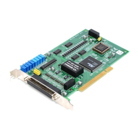
  9. Advantech PCE-3029 Installation and operation manual

Advantech PCE-3029 Installation and operation manual

Other manuals for PCE-3029

1

This manual suits for next models

1

Other Advantech Computer Hardware manuals

Advantech SOM-4463D-S8B2E User manual

Advantech

Advantech SOM-4463D-S8B2E User manual

Advantech ECU-479 Series User manual

Advantech

Advantech ECU-479 Series User manual

Advantech ECU-P1522LPE Installation and operation manual

Advantech

Advantech ECU-P1522LPE Installation and operation manual

Advantech PCM-3643 User manual

Advantech

Advantech PCM-3643 User manual

Advantech HPC-6240 User manual

Advantech

Advantech HPC-6240 User manual

Advantech SOM-MZ10 Installation and operation manual

Advantech

Advantech SOM-MZ10 Installation and operation manual

Advantech PCLD-8751 User manual

Advantech

Advantech PCLD-8751 User manual

Advantech MIC-300 Installation and operation manual

Advantech

Advantech MIC-300 Installation and operation manual

Advantech USB-4750 User manual

Advantech

Advantech USB-4750 User manual

Advantech PCL-746+ User manual

Advantech

Advantech PCL-746+ User manual

Advantech MIO-5377 User manual

Advantech

Advantech MIO-5377 User manual

Advantech UNO-3300G Series User manual

Advantech

Advantech UNO-3300G Series User manual

Advantech PCA-6275 User manual

Advantech

Advantech PCA-6275 User manual

Advantech PCM-4153 User manual

Advantech

Advantech PCM-4153 User manual

Advantech RSB-4221 User manual

Advantech

Advantech RSB-4221 User manual

Advantech PCM-3641P Installation and operation manual

Advantech

Advantech PCM-3641P Installation and operation manual

Advantech PCA-6108P6 Installation and operation manual

Advantech

Advantech PCA-6108P6 Installation and operation manual

Advantech AIMB-588 User manual

Advantech

Advantech AIMB-588 User manual

Advantech MIC-75M20 Installation and operation manual

Advantech

Advantech MIC-75M20 Installation and operation manual

Advantech PCIE-1803 User manual

Advantech

Advantech PCIE-1803 User manual

Advantech SNMP-1000-E2B1E Safety guide

Advantech

Advantech SNMP-1000-E2B1E Safety guide

Advantech PCA-6176 Series User manual

Advantech

Advantech PCA-6176 Series User manual

Advantech PCA-6157 User manual

Advantech

Advantech PCA-6157 User manual

Advantech PCA-6654 User manual

Advantech

Advantech PCA-6654 User manual

Popular Computer Hardware manuals by other brands

Toshiba TOSVERT VF-MB1/S15 IPE002Z Function manual

Toshiba

Toshiba TOSVERT VF-MB1/S15 IPE002Z Function manual

Shenzhen MEITRACK MVT380 user guide

Shenzhen

Shenzhen MEITRACK MVT380 user guide

TRENDnet TEW-601PC - SUPER G MIMO WRLS PC CARD user guide

TRENDnet

TRENDnet TEW-601PC - SUPER G MIMO WRLS PC CARD user guide

StarTech.com CF2IDE18 instruction manual

StarTech.com

StarTech.com CF2IDE18 instruction manual

Texas Instruments LMH0318 Programmer's guide

Texas Instruments

Texas Instruments LMH0318 Programmer's guide

Gateway 8510946 user guide

Gateway

Gateway 8510946 user guide

Devon IT TC2D Quick setup guide

Devon IT

Devon IT TC2D Quick setup guide

Krüger & Matz Air Shair2 owner's manual

Krüger & Matz

Krüger & Matz Air Shair2 owner's manual

Crystalio VPS-2300 quick guide

Crystalio

Crystalio VPS-2300 quick guide

MYiR FZ3 user manual

MYiR

MYiR FZ3 user manual

Protech Systems BC-K200 Quick reference guide

Protech Systems

Protech Systems BC-K200 Quick reference guide

Miranda DENSITE series DAP-1781 Guide to installation and operation

Miranda

Miranda DENSITE series DAP-1781 Guide to installation and operation

Sierra Wireless Sierra Wireless AirCard 890 quick start guide

Sierra Wireless

Sierra Wireless Sierra Wireless AirCard 890 quick start guide

Leadtek Killer Xeno Pro Quick installation guide

Leadtek

Leadtek Killer Xeno Pro Quick installation guide

Star Cooperation FlexTiny 3 Series Instructions for use

Star Cooperation

Star Cooperation FlexTiny 3 Series Instructions for use

Hotone Ampero user manual

Hotone

Hotone Ampero user manual

Connect Tech Xtreme/104-Express user manual

Connect Tech

Connect Tech Xtreme/104-Express user manual

Yealink WF50 user guide

Yealink

Yealink WF50 user guide

manuals.online logo
manuals.online logoBrands
  • About & Mission
  • Contact us
  • Privacy Policy
  • Terms and Conditions

Copyright 2025 Manuals.Online. All Rights Reserved.

PCE-3029/PCE-4129 Startup Manual 1
Before you begin installing your card, please make sure that
the following items have been shipped:
1. 1 x PCE-3029 or 4129 PICMG 1.3 System Host Board
2. 1 x CD with utility
3. 1 x PCE-3029/PCE-4129 Startup Manual
4. 1 x Serial ATA HDD data cable
5. 1 x Serial ATA HDD power cable
6. 1 x 2-port COM cable kit
7. 1 x 4-port USB 2.0 cable kit
8. 1 x 2-port USB 3.0 cable kit
9. 1 x Power converter (Connecting from peripheral power
connector on power supply to PWR1 on board)
10. 1 x Keyboard and mouse Y cable
11. 1 x Jumper package
12. 1 x Warranty card
If any of these items are missing or damaged, please con-
tact your distributor or sales representative immediately.
Note 1: For detailed contents of PCE-3029/PCE-4129,
please refer to information on the enclosed CD-
ROM (in PDF format).
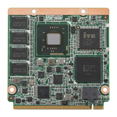
PCE-3029/PCE-4129 LGA1151 Intel®Xeon®,
Core™ i7/i5/i3/Celeron®/Pentium®PICMG1.3 Half-size
System Host Board with DDR4/Dual GbE LAN
Startup Manual
General
• CPU: LGA1151-socket Core™ i7/i5/i3, Pentium® and
Xeon® E3-1200v5 series processors
Note: Only PCE-4129 supports Intel® Xeon® processors.
• L2 cache: Please refer to CPU specication for detailed
information.
• BIOS: AMI SPI BIOS (128 Mb SPI)
• System chipset: Intel® C236 (PCE-4129); Intel® H110
(PCE-3029)
• System memory:
- PCE-4129: Up to 32 GB in two 260-pin SODIMM sock-
ets. Supports dual-channel DDR4 1866/2133 SDRAM
with or without ECC function.
- PCE-3029: Up to 32 GB in two 260-pin SODIMM sock-
ets. Supports dual-channel DDR4 1866/2133 SDRAM
without ECC function.
• SATA hard disk drive interface: PCE-3029 sup-
ports three SATA 3.0 ports without RAID function, and
PCE-4129 supports four SATA 3.0 ports with SW RAID
0,1,5,10.
• Serial ports: Two RS-232 serial ports
• Keyboard/mouse connector: Supports one external
6-pin header
• Watchdog timer: Programmable 1~255 sec
• USB: USB 3.0 x 3, USB 2.0 x 7
• GPIO: One programmable 8-bit GPIO pin-header
Display
• Chipset: Intel®HD Graphics embedded in the processor
Ethernet Interface
• Chipset supports:
-
LAN 1: Intel
®
I219V (PCE-3029) and I219LM (PCE-4129).
- LAN 2: Intel
®
I210AT (PCE-3029) and I210AT (PCE-4129).
• Connection: 2 x on-board RJ-45 connectors with LED
indicators
Mechanical and Environmental
• Dimensions: (L x W): 167.64 x 126.39 mm
• Power supply voltage: +3.3 V, +5 V, +12 V, 5 V
SB
• Power requirements:
PCE-3029:
Intel® Core™ i7-6700 (3.4GHz), DDR4 2133 8GB * 2
Voltage 12V 5V 3.3V 5VSB -12V -5V
Current (A) 4.6 0.01 0.32 0.08 0 0
Specications
Packing List
For more information on this and other Advantech
products, please visit our website at:
http://www.advantech.com
http://www.advantech.com/eplatform
For technical support and service, please visit our
support website at:
http://support.advantech.com.tw/support/default.
aspx
This manual is for the PCE-3029/PCE-4129 Series
Rev. B3.
Part No. 2001302911
Printed in China
2nd Edition
October 2022
2 PCE-3029/PCE-4129 Startup Manual
PCE-4129:
E3-1225 v5 (3.30GHz), DDR4 2133 8GB *2
Voltage 12V 5V 3.3V 5VSB -12V -5V
Current (A) 4.6 0.01 0.32 0.08 0 0
• Operating temperature: 0 ~ 60 °C (depending on CPU)
• Weight: 0.33 kg (weight of board)
The board has a number of jumpers that allow you to congure
your system to suit your application. The table below lists the
function of each of the jumpers and connectors.
Connectors
Label Function
LPT1 Parallel port, supports SPP/EPP/ECP
mode
LAN1 PCE-3029: Intel® I219V
PCE-4129: Intel® I219LM
LAN2 PCE-3029: Intel® I210AT
PCE-4129: Intel® I210AT
VGA1 VGA connector
KBMS1 External keyboard/mouse connector
COM12 Box header for RS-232*2
FP1 HDD LED, power LED, SNMP SM_Bus,
reset, power on/o󰀨
JCASE1 Case open
CPUFAN1 CPU FAN connector (4-pin)
LANLED1 LAN1/2 LED connector
HDAUD1 HD audio extension module connector
USB1 USB port 1 (USB 3.0 port)
USB23 USB port 2, 3 (USB 3.0 port)
USB45 USB port 4, 5 (USB 2.0)
USB67 USB port 6, 7 (USB 2.0)
USB89 USB port 8, 9 (USB 2.0)
USB11 Type A connector on board (USB 2.0)
SATA0 Serial ATA1 (SATA 3.0)
SATA1 Serial ATA2 (SATA 3.0)
SATA2 Serial ATA3 (SATA 3.0)
SATA3 Serial ATA4 (PCE-4129: 3.0)
CPU1 CPU Socket
DIMMA1 Memory connector channel A
DIMMB1 Memory connector channel B
GPIO1 GPIO pin header
LPC1 Low pin count module expansion pin-
header
PWR1 12 V, 5 V power connector
DVI1
DVI connector
DP1
Display pin header to stack board
(Display type depends on optional stack
board)
EXPCIE1 Mini PCIe pin header to stack board
MINIPCIE MSATA
M-SATA (default) or Mini PCIe connec-
tor (optional for PCE-4129)
Jumpers
Label Function
JCMOS1 CMOS clear
JWDT1+JOBS1 Hardware monitor alarm+watchdog
timer output selection
JME1 Enable ME
JCMOS1: Clear CMOS
Closed Pins Result
1-2 Keep CMOS (Default)
2-3 Clear CMOS
JOBS1+JWDT1: Hardware monitor alarm+watchdog
timer output selection
Function Jumper Setting
2-3 Enable watchdog timer (Default)
4-5 Enable Hardware monitor alarm
(Default)
JME1: Enable ME
Closed Pins Result
1-2 Enable ME
(Default)
2-3 Disable ME
1 2 3 4 5
123
Jumpers and Connectors
Specications
(Cont.)
Jumpers and Connectors (Cont.)
PCE-3029/PCE-4129 Startup Manual 3
The drivers for the PCE-3029 are located on the software
installation CD. Please click through the folder and follow
the on-screen instructions to install them.
Caution! The computer is supplied with a battery-powered
real-time clock circuit. There is a danger of
explosion if the battery is incorrectly replaced.
Replace only with the same or equivalent type
recommended by the manufacturer. Discard
used batteries according to the manufacturer’s
instructions.
This device complies with the requirements in Part 15 of
the FCC rules. Operation is subject to the following two
conditions:
1. This device may not cause harmful interference;
2. This device must accept any interference received,
including interference that may cause undesired opera-
tion.
Software Installation
Declaration of Conformity
Board Layout
Board Layout: Jumper and Connector Locations
DIMM B1
DIMM A1
PWR1 FP1 USB45
USB89
USB11
CPU FAN1
USB67
USB1
LAN2
LAN1
BIOS SPI1
VGA1
DVI1
PCH: C236
DP1
JCASE1
LPC1
GPIO1
LGA1151
USB23
SATA0 SATA1
SATA3 SATA2
EXPCIE1
LAN LED1
KBMS1
HDAUD1
COM12
JWDT1 JOBS1
JCOMS1
JME1
4 PCE-3029/PCE-4129 Startup Manual
To power on PCE-3029/PCE-4129 with backplanes, please ensure that the below connectors and jumpers are correctly con-
nected and chosen.
How to Power on PCE-3029/PCE-4129
PWR1
Cable: 1703040100
PSON1
123
123
PSON1: ATX/AT Mode Selection
Jumper Setting Function
1-2 AT mode
2-3 (Default) ATX mode