vii ARK-3390 User Manual
Contents
Chapter 1 General Introduction ...........................1
1.1 Introduction ...............................................................................................2
1.2 Product Feature ........................................................................................2
1.3 Chipset......................................................................................................3
1.3.1 Functional Specification................................................................3
1.4 Mechanical Specifications.........................................................................5
Figure 1.1 ARK-3390 Dimensions...............................................5
1.4.1 Dimensions...................................................................................5
1.4.2 Weight...........................................................................................5
1.5 Electrical Specifications ............................................................................6
1.5.1 Power supply Voltage...................................................................6
1.5.2 Power supply Current ...................................................................6
1.5.3 RTC Battery..................................................................................6
1.6 Environmental Specifications....................................................................6
1.6.1 Operating temperature..................................................................6
1.6.2 Relative Humidity..........................................................................6
1.6.3 Vibration During Operation ...........................................................6
1.6.4 Shock During Operation................................................................6
Chapter 2 H/W Installation....................................7
2.1 Introduction ...............................................................................................8
2.2 Jumpers ....................................................................................................8
2.2.1 Jumper Description.......................................................................8
2.2.2 Jumper and Connector Location...................................................9
2.3 Connectors..............................................................................................11
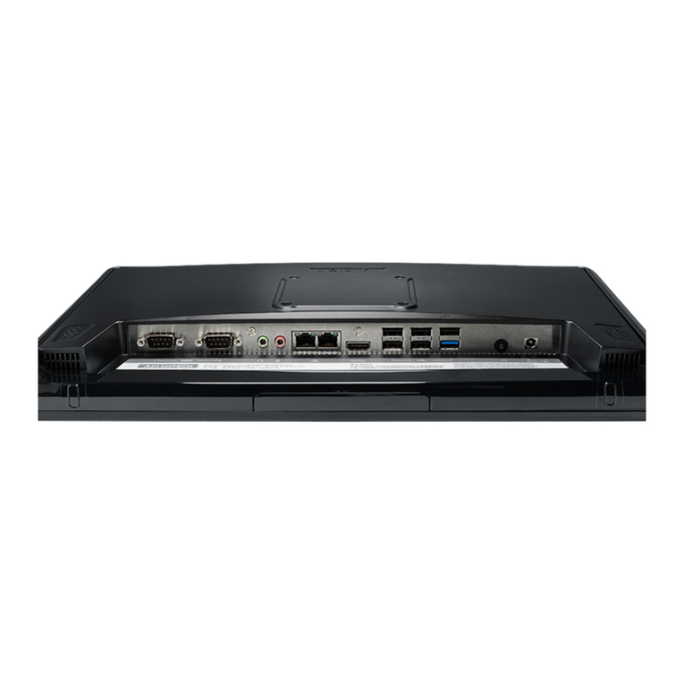
Figure 2.1 ARK-3389 IO connectors drawing............................11
2.3.1 ARK-3390 External I/O Connectors............................................12
Figure 2.2 COM connector ........................................................12
Table 2.1: COM Standard Serial Port Pin Assignments............12
Figure 2.3 DIO connector ..........................................................13
Table 2.2: Table 2.2: DVI-D Connector Pin Assignments ........13
Figure 2.4 Ethernet connector...................................................13
Table 2.3: RJ-45 Connector Pin Assignments...........................13
Figure 2.5 Audio connector........................................................14
Table 2.4: Audio Connector Pin Assignments...........................14
Figure 2.6 DIO connector ..........................................................14
Table 2.5: DIO Connector Pin Assignments..............................14
Figure 2.7 USB connector .........................................................15
Table 2.6: USB Connector.........................................................15
Figure 2.8 Power Button............................................................15
Figure 2.9 LED Indicators..........................................................15
Figure 2.10 Power Input Connector............................................15
Table 2.7: Power connector Pin Assignments...........................16
2.4 Installation...............................................................................................16
2.4.1 HDD Installation..........................................................................16
Figure 2.11Unscrew the HDD door screws ................................16
Figure 2.12Assemble HDD and HDD frame by 4 Screws ..........17
Figure 2.13Screw on the HDD damper screws to assemble the
HDD door and HDD frame........................................17
Figure 2.14Connect the HDD cables..........................................18
2.4.2 Memory Installation.....................................................................19
Figure 2.15Install the memory module into the SO-DIMM socket at
the bottom of the Main board....................................19
