ix MIC-7420 User Manual
Contents
Chapter 1 Overview...............................................1
1.1 Introduction ............................................................................................... 2
1.2 Specification.............................................................................................. 2
1.3 Environment .............................................................................................. 2
Table 1.1: Environment ............................................................... 2
1.4 Dimensions ............................................................................................... 3
Figure 1.1 MIC-7420 Dimension.................................................. 3
Chapter 2 Industrial Motherboard .......................5
2.1 Introduction ............................................................................................... 6
2.2 System View and LED Indicator................................................................ 6
2.2.1 System View ................................................................................. 6
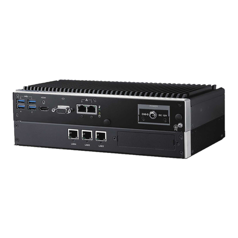
Figure 2.1 Front View .................................................................. 6
Figure 2.2 Rear View ................................................................... 6
2.2.2 System Status LED Indicator ........................................................ 6
2.2.3 Network Interface LED Indicator ................................................... 7
2.2.4 Serial Port Status LED Indicator ................................................... 7
2.3 Jumpers and Connectors .......................................................................... 7
2.3.1 Jumper Description ....................................................................... 7
2.3.2 Jumper and Connector Location................................................... 8
Figure 2.3 Jumper and Connector Location on Main Board ........ 8
Table 2.1: Jumpers...................................................................... 8
Table 2.2: JCMOS1: Clear CMOS Settings................................. 9
Table 2.3: PSON1: Start-up Mode Selection............................... 9
Table 2.4: VCCGPIO1: GPIO Voltage Selection ......................... 9
2.4 I/O Connector.......................................................................................... 10
2.4.1 COM Connector .......................................................................... 10
Table 2.5: COM Connectors...................................................... 10
2.4.2 DVI-D Connector......................................................................... 10
Table 2.6: DVI-D Connector ...................................................... 10
2.4.3 DVI-I Connector .......................................................................... 11
Table 2.7: DVI-I Connector........................................................ 11
2.4.4 USB 2.0 Connector ..................................................................... 11
Table 2.8: USB2.0 Pin Assignment ........................................... 11
2.4.5 USB 3.0 Connector ..................................................................... 12
Table 2.9: USB 3.0 Pin Assignment .......................................... 12
2.4.6 Audio-in Connector ..................................................................... 12
2.4.7 LAN Connector ........................................................................... 13
Table 2.10: LAN Connector ......................................................... 13
Chapter 3 System Installation............................15
3.1 Introduction ............................................................................................. 16
3.1.1 Installing mainboard mini-PCIe and M.2 cards ........................... 16
Figure 3.1 Installing M.2 and mini-PCIe..................................... 16
3.1.2 Installing the HDD Module .......................................................... 16
Figure 3.2 Installing HDD Module.............................................. 17
3.1.3 Installing the Top Cover .............................................................. 18
Figure 3.3 Installing the Top Cover............................................ 18
3.1.4 Installing Ears and Handles ........................................................ 19
Figure 3.4 Installing the Foot Stand........................................... 19
3.1.5 Installing the add-on card............................................................ 19
