
9© 2015 OJ Electronics A/S - EHT Haustechnik GMBH
Es empfiehlt sich, Kabel und Fühler in einem im Boden eingelas-
senen, nicht leitenden Installationsrohr anzubringen. Mit ver-
schlossenem Rohrende sollte das Rohr so hoch wie möglich in der
Estrichschicht eingebettet sein. Alternativ kann der Fühler direkt im
Boden eingebettet werden. Das Fühlerkabel ist in einem separaten
Rohr oder getrennt von Leistungskabeln zu verlegen.
Der Bodenfühler muss zwischen den Heizkabelschleifen zentriert
werden.
Das Fühlerkabel kann mit einem separaten Zweileiterkabel bis zu
100 m verlängert werden. Freie Leiter in einem z. B. das Boden-
heizkabel mit Strom versorgenden Mehrleiterkabel dürfen nicht
verwendet werden. Die Schaltspitzen einer derartigen Stromversor-
gung können Interferenzen auslösen die eine optimale Thermo-
statfunktion behindern. Wird ein abgeschirmtes Kabel verwendet,
darf die Abschirmung nicht geerdet werden. Das Zweileiterkabel
ist in einem separaten Rohr oder getrennt von Leistungskabeln zu
verlegen.
Montage eines Thermostats mit eingebautem Fühler
Der Raumfühler wird zur Regelung der Komforttemperatur in
Räumen eingesetzt. Der Thermostat ist auf der Wand ca. 1,5 m
über dem Boden und freie Luftzirkulation um ihn gestattend zu
montieren. Zugluft und direkte Sonneneinstrahlung oder andere
Wärmequellen müssen vermieden werden.
ABB. 4 – ÖFFNEN DES THERMOSTATGEHÄUSES
1. Den Schiebeschalter nach unten in Position Aus „0“ schieben.
2. Zum Lösen der Frontabdeckung NUR einen kleinen Schrau-
bendreher benutzen. Diesen in den Schlitz an der Unterseite
der Frontabdeckung einstecken, nach oben drücken und die
Frontabdeckung festhalten.
3. Danach vorsichtig die Frontabdeckung entfernen, zuerst von
unten am Thermostat und dann von oben.
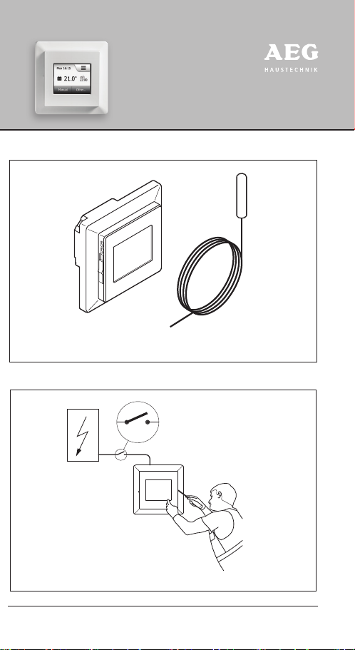
ABB. 5 – ANSCHLÜSSE
Die Leiter gemäß Schaltplan anschließen. Die Leiterdrähte müssen
wie folgt angeschlossen werden:
Klemme 1: Nullleiter (N)
Klemme 2: Phase (L)
Klemme 3-4: Ausgang, max. 16A
Klemme X: Nicht benutzen
FRTD 903 TC Deutsch
Klemme 5-6: Externer Bodenfühler
ABB. 6 + 7 – MONTAGE DES THERMOSTATS
1. Den Thermostat in der Wanddose montieren.
2. Den Rahmen anpassen und den Deckel vorsichtig auf den Ther-
mostat aufsetzen – beginnend mit dem oberen Teil des Deckels
und dann dessen unteren Teil. Bitte beachten, dass sich sowohl
der Schiebeschalter am Deckel als auch der zugehörige Stift im
Thermostat in unterster Position befinden.
3. Den Deckel mit leichtem, gleichmäßigem Druck auf dem
Gehäuse einrasten. Achtung! Nicht auf die Ecken der Display-
Abdeckung oder auf das Display drücken.
KEINESFALLS den Thermostat bei den vier Befestigungsschellen
auf der Rückseite önen.
ABB. 8 – BEDIENUNG DES THERMOSTATS
Ein EIN/AUS-Schalter befindet sich auf der linken Seite des Ther-
mostats: Stellung oben ist EIN – Stellung unten ist AUS.
Der resistive Touchscreen erfordert ein weiches Antippen mit der
Fingerspitze um die Berührung zu registrieren.
Erste Einstellungen:
Zur ersten Inbetriebnahme des Thermostats den Betriebsschalter
in Position Ein „I“ schieben. Der Installationsassistent auf dem
Touchscreen führt Sie durch das Setup von:
1. Region
2. Sprache
3. Datum
4. Uhrzeit
5. Bodentyp
Programmierung
Siehe Benutzerhandbuch:
http://www.aeg-haustechnik.de/fachpartner/produkte/gaw/fuss-
bodenheizungen/
FRTD 903 TC Deutsch


 User manual")


