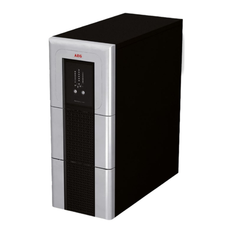
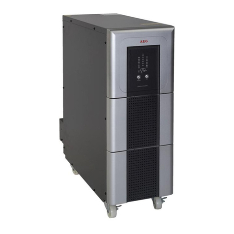
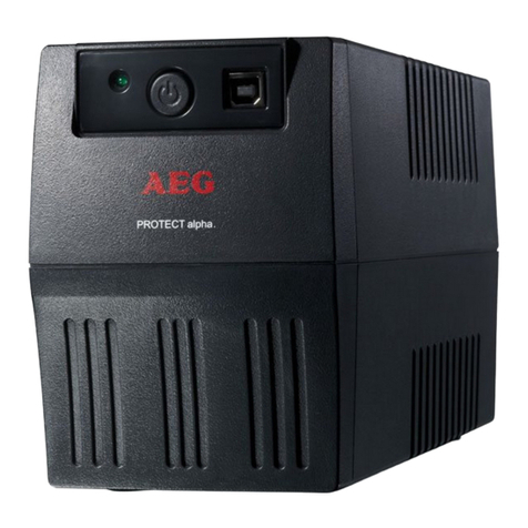
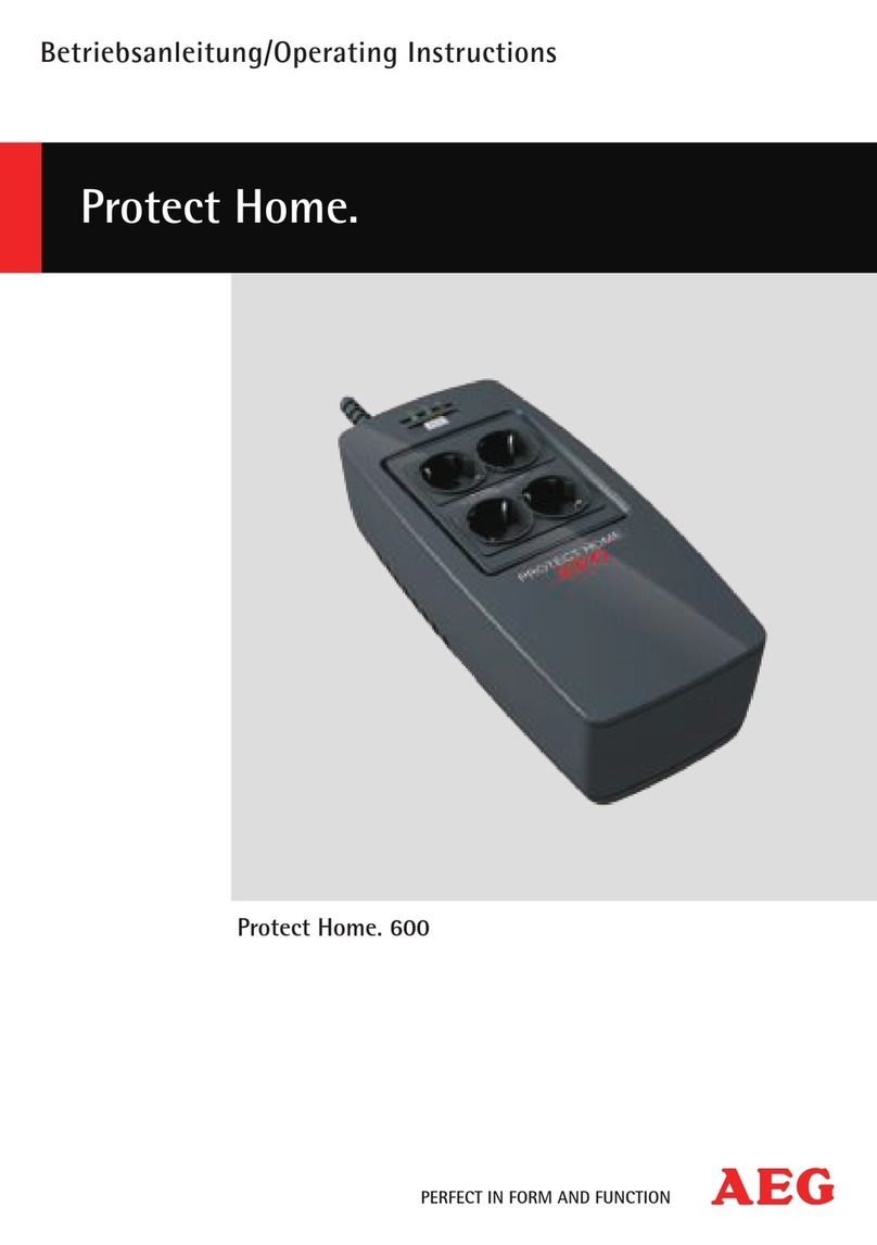
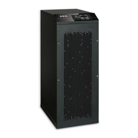
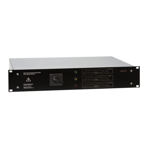
AEG Protect A Series User manual

Protect A 500 LCD
Protect A 700 LCD
Protect A 1200 LCD
Protect A 1600 LCD
PROTECT A
User Manual

2
Status
StatusStatus
Status
Change
ChangeChange
Change
Date
DateDate
Date
Name
NameName
Name
00 Created 29.01.2019 G rtan
REVISION

3
Thank y u f r purchasing the AEG PS UPS Pr tect A LCD fr m AEG P wer
S luti ns.
Safety inf rmati n and perating instructi ns are included in this manual. T
ensure c rrect use f the UPS, please read this manual th r ughly bef re
perating it. Use this manual pr perly.

4
Warranty
WarrantyWarranty
Warranty
& Service
& Service & Service
& Service Inf rmati n:
Inf rmati n:Inf rmati n:
Inf rmati n:
Thanks f r buying this UPS pr duct.
Please f ll w the instructi ns in the pr duct manual and if
applicable the s ftware installati n manual, t have the maximum
use f y ur pr duct.
Installing the s ftware:
Installing the s ftware:Installing the s ftware:
Installing the s ftware:
If y ur pr ducts c mes with s ftware y u will find a CD R m in
the b x c ntaining the s ftware.
Please f ll w the instructi ns when installing the s ftware.
Y u can d wnl ad the s ftware, manual and sh rt reference manual
at the f ll wing site: www.ups-s ftware-d wnl ad.c m.
Pr blem s lving:
Pr blem s lving:Pr blem s lving:
Pr blem s lving:
Please check the chapter in y ur manual (hardware and
s ftware) n pr blem s lving.
If this n t s lve y ur pr blem please c ntact y ur reseller f r advice.
Service and Maintenance:
Service and Maintenance:Service and Maintenance:
Service and Maintenance:
If the pr duct requires service r maintenance, n matter it is under r
ut f warranty peri d always c ntact y ur reseller f r the
pr cedures. In any case always make sure that service r
maintenance n the pr duct are perf rmed by a qualified technician.

5
1. NOTES ON THESE OPERATING .............................................................................. 6
1.1 Duty t Pr vide Inf rmati n .............................................................................. 6
1.2 Please Read These Instructi ns Carefully Pri r t
C mmissi ning!............................................................................................................. 6
1.3 Validity................................................................................................................................... 6
1.4 Warranty and Liability............................................................................................. 6
1.5 Handling .............................................................................................................................. 7
1.6 C pyright ............................................................................................................................ 7
2. SYSTEM OVERVIEW ............................................................................................................ 8
2.1 Brief Overview ................................................................................................................ 8
2.2 Principle f Operati n ............................................................................................. 9
3. SAFETY ........................................................................................................................................... 11
3.1 General Safety Instructi ns ............................................................................... 11
3.2 Safety Instructi ns f r Pr tect A .................................................................. 11
3.3 Technical Data .............................................................................................................14
4. SET-UP ........................................................................................................................................... 17
4.1 Unpacking and Inspecti n ................................................................................ 17
4.2 Installati n Site ............................................................................................................ 18
4.3 Fr nt Panel...................................................................................................................... 18
4.4 Back Panel ....................................................................................................................... 19
4.5 Display................................................................................................................................20
5. INSTALLATION AND INITIAL SETUP.............................................................. 23
5.1 Check ................................................................................................................................... 23
5.2 Placement and St rage C nditi ns ......................................................... 23
5.3 C nnect t Utility and Charge ...................................................................... 23
5.4 C nnect the L ads.................................................................................................. 24
5.5 C nnect 1000Mb Ethernet f r Surge Pr tecti n........................ 25
5.6 C nnect USB Cable ................................................................................................ 25
5.7 Turn On/Off the Unit ............................................................................................ 25
6. SOFTWARE INSTALLATION ON YOUR PC ................................................ 26
7. SMART BATTERY FUNCTION ................................................................................ 27
8. TROUBLESHOOTING ...................................................................................................... 28
9. MAINTENANCE ..................................................................................................................... 29
9.1 Battery Replacement ............................................................................................ 29
10. STORAGE AND DISPOSAL .......................................................................................... 31
CONTENT
S

6
1.1
Duty t Pr vide Inf rmati n
These perating instructi ns will help y u t install and perate the
Uninterruptible P wer Supply (UPS), Pr tect A 500 LCD, Pr tect A
700 LCD, Pr tect A 1200 LCD and Pr tect A 1600 LCD - referred t
as Pr tect A in this d cument - safely and pr perly, and f r its
intended purp se. These perating instructi ns c ntain imp rtant
inf rmati n f r av iding dangers.
1.2
Please Read These
Instructi ns Carefully Pri r t
C mmissi ning!
These perating instructi ns are a c mp site part f Pr tect A.
The wner f this unit is bliged t c mmunicate the full c ntent f
these perating instructi ns t all pers nnel transp rting r starting
the Pr tect A r perf rming maintenance r any ther w rk n the
unit, with ut the inf rmati n having t be requested.
1.3
Validity
These perating instructi ns c mply with the current technical
specificati ns f Pr tect A at the time f publicati n. The c ntents d
n t c nstitute subject matter f the c ntract, but
serve f r inf rmati n purp ses nly.
1.4
Warranty and Liability
We reserve the right t alter any specificati ns given in these
perating instructi ns, especially with regard t technical data and
perati n, pri r t start-up r as a result f service w rk. Claims in
c nnecti n with supplied g ds must be submitted within ne week
f receipt, al ng with the packing slip. Subsequent claims cann t be
c nsidered.
The warranty d es n t apply f r damage caused by n nc mpliance
with these instructi ns (such damage als includes damage t the
warranty seal). AEG will accept n liability f r c nsequential damage.
AEG will rescind all bligati ns such as warranty agreements, service
c ntracts, etc. entered int by AEG r its representatives with ut
pri r n tice in the event f maintenance and repair w rk being
1.
NOTES ON THESE OPERA
TING
INSTRUCTIONS

7
carried ut with anything ther than riginal AEG parts r spare parts
purchased fr m AEG.
1.5
Handling
Pr tect A is designed and c nstructed s that all necessary steps f r
start-up and perati n can be perf rmed with ut any internal
manipulati n f the unit. Maintenance and repair w rk may nly be
perf rmed by trained and qualified pers nnel.
Illustrati ns are pr vided t clarify and facilitate certain steps.
If danger t pers nnel and the unit cann t be ruled ut in the
case f certain w rk, it is highlighted acc rdingly by pict graphs
explained in the safety regulati ns f chapter 3.
1.6
C pyright
© C pyright 2018 AEG P wer S luti ns GmBH, Warstein-Belecke,
Germany. All rights reserved.
This d cument must n t be repr duced, either in wh le r in part,
with ut the express permissi n f AEG P wer S luti ns GmBH.
AEG is a registered trademark used under license fr m AB Electr lux.
This pr
This prThis pr
This pr duct c mplies with the safety and envir nmental regulati ns
duct c mplies with the safety and envir nmental regulati ns duct c mplies with the safety and envir nmental regulati ns
duct c mplies with the safety and envir nmental regulati ns
in EU.
in EU.in EU.
in EU.
If the time arises t thr w away y ur pr duct, please recycle all the
c mp nents p ssible.
Batteries and rechargeable batteries are n t t be disp sed in y ur
d mestic waste! Please recycle them at y ur l cal recycling p int.
T gether we can help t pr tect the envir nment.

8
Pr tect A is an u
uu
uninterruptible p
pp
p wer s
ss
supply (UPS) f r essential l ads
such as PCs, w rkstati ns, relatively small-scale telec mmunicati n
equipment and similar devices.
The Pr tect A series is a c mpact, interactively perating step wave
UPS available with n minal p wer utput ratings 500, 700, 1200 and
1600 VA.
This d cument describes all types.
2.1 Brief Overview
LCD display, a pushbutt n switch and fast charging USB p rt are
l cated n the fr nt f the UPS f r straightf rward m nit ring and
perati n. The display unit with rec gnisable ic n functi ns clearly
signals the particular perating c nditi n: n rmal perati n, battery
discharge, battery status, fault.
The c nnecti ns f r the mains and the l ads are l cated n
the rear f the Pr tect A, as are the c mmunicati n interfaces and
c nnecti ns f r teleph ne lines. Imp rtant UPS data is m nit red
permanently and transferred t the c mputer via USB r the RS232
interface and using the C mpuWatch r WinP wer s ftware.
Features f Pr tect A:
•VI (line – interactive) pr tecti n techn l gy
•Aut matic v ltage regulati n against mains v ltage deviati ns
(AVR)
•Micr pr cess r c ntr l f r high reliability and efficiency
•DC c ld start functi n as well as aut restart while AC is in
rec very
•M dern battery management with integrated pr tecti n against
exhaust. discharge and verl ading
•User-friendly graphic LCD display with ptimum legibility
•Intelligent m nit ring system with USB and RS232 interfaces f r
fax, m dem and ph ne
•RJ45 (in/ ut) 1000Mb Ethernet surge pr tecti n
•Pr vides DC 5.1V 2.0Amp USB charger n fr nt panel
•C mpuWatch and WinP wer s ftware f r shutd wn, status
messages and measurement values f r all maj r perating
systems (incl. Wind ws, Mac, Linux)
2.
SYSTEM OVERVIEW

9
•C mpact design / with ut fan n all units except Pr tect A 1600
LCD which has a fan n the back f the unit
•Fully c mpliant with generat r input
2.2 Principle f Operati n
The UPS is c nnected t a sh ckpr f s cket between the public
utility’s mains and the l ads t be pr tected.
Under n rmal perating c nditi ns, i.e. if Pr tect A is supplied with
mains v ltage, the battery charger will ensure that the battery is
always c mpletely charged.
During this perating status, the l ads c nnected t Pr tect A are
supplied with v ltage via mains filters which pr vide effective
pr tecti n against mains v ltage peaks and high-frequency faults.
In case f sustained mains under v ltage r verv ltage within
defined ranges, the aut matic v ltage regulat r (AVR) further
stabilises the l ad v ltage. As a result, v ltage fluctuati ns in the
public utility’s mains are reduced t a level which is acceptable f r the
l ads. This is perf rmed with ut rec urse t the internal energy
st rage, s mething which in turn has a p sitive effect n battery
availability.
Pr tect A UPS bl ck diagram
The static bypass switch is activated in the event f a mains failure.
The inverter then takes ver the v ltage supply f the c nnected
l ads, in rder t prevent the risk f data l ss r damage t the l ads.

10
Pr tect A supplies v ltage until the battery is discharged r y ur IT
system has been shut d wn and switched ff pr perly.
The standby time mainly depends n the c nnected l ads. If the
mains p wer supply is back t n rmal values, the UPS will
aut matically switch back the l ads t mains supply. The battery
charger will then recharge the battery.
F r safety reas ns (as required by German standards, VDE), the
mains input in the unit will be disc nnected by a tw -p le switch in
the event f a mains failure. Energy backfeed t the mains and
v ltage supply t the pins f the mains c nnect r are thus reliably
av ided.
Furtherm re, additi nal measures ensure effective pr tecti n f r the
data/netw rk interface.

11
3.1 General Safety Instructi ns
Read these perating instructi ns carefully pri r t c mmissi ning f
Pr tect A UPS and bserve the safety instructi ns!
Only use the unit if it is in a technically perfect c nditi n and always
in acc rdance with its intended purp se, while being aware f safety
and danger aspects, and in acc rdance with the perating
instructi ns! Immediately eliminate any faults that c uld be
detrimental t safety.
The f ll wing pict grams are used in these perating instructi ns t
identify dangers and imp rtant inf rmati n:
3.2 Safety Instructi ns f r Pr tect A
This chapter c ntains imp rtant instructi ns f r Pr tect A. These
must be f ll wed during assembly, perati n and maintenance f the
uninterruptible p wer supply and the batteries.
The UPS is live, and the v ltage can be danger us. The unit may nly
be pened by trained and qualified pers nnel. Repairs may nly be
carried ut by qualified cust mer service staff!
The utput may be live, even if the UPS is n t c nnected t the
mains supply, as the UPS has its wn internal p wer supply (battery)!
3.
SAFETY

12
F r health and safety reas ns, the unit must be earthed c rrectly!
Pr tect A may nly be perated with r c nnected t a 220 / 230 /
240 VAC mains with pr tective gr unding using a mains c nnecti n
cable with PE c nduct r (included in the delivery) that has been
tested in acc rdance with German standards (VDE).
Risk f burning!
Risk f burning!Risk f burning!
Risk f burning!
The battery has p werful sh rt-circuit currents. Inc rrect c nnecti n
r is lati n faults can lead t melting f the plug c nnecti ns,
sparking p tential and severe burns!
The unit has a warning signal that s unds when the battery v ltage
f Pr tect A is exhausted r when the UPS is n t w rking in its
n rmal m de.
Observe the f ll wing safety instructi ns t ensure permanent
perati nal safety f and safe w rk with the UPS:
•D n t dismantle the UPS! (The UPS d es n t c ntain any parts that
require regular maintenance. Bear in mind that the warranty will be
invalidated if the unit is pened!)
•D n t install the unit in direct sunshine r in cl se pr ximity f
heaters!
•The unit is designed t be installed inside in heated r ms. Never
install the UPS in the vicinity f water r in an excessively damp
envir nment!
•C ndensati n may ccur if the UPS is br ught fr m a c ld
envir nment int the r m where it is t be installed. The UPS must
be abs lutely dry pri r t startup. As a result, leave it t acclimatise
f r at least tw h urs.
•Never c nnect the mains input and the UPS utput!
•Ensure that n fluids r f reign b dies can penetrate the UPS!

13
•D n t bl ck the air vents f the unit! Make sure, f r example, that
children d n t insert any bjects in the ventilati n penings!
•D n t c nnect h useh ld appliances such as hairdryers t the UPS!
•The mains c nnecti n sh uld be near the unit and easily accessible
t facilitate disc nnecting the AC input r pulling ut the plug!
•During perati n, d n t disc nnect the mains c nnecti n cable fr m
the UPS r fr m the s cket utlet in the building (sh ckpr f s cket),
therwise the pr tective gr unding f the UPS and all the l ads
c nnected t it will be cancelled.
Danger! Electric sh cks!
Danger! Electric sh cks!Danger! Electric sh cks!
Danger! Electric sh cks!
Even after the mains v ltage has been disc nnected, the c mp nents
within the UPS remain c nnected t the battery and can thus cause
electric sh cks. It is theref re imperative t disc nnect the battery
circuit bef re carrying ut any maintenance r repair w rk!
If it is necessary t replace the battery r carry ut maintenance w rk,
this must be d ne by r under the supervisi n f a specialist familiar
with batteries and the necessary safety precauti ns! Only auth rized
Only auth rized Only auth rized
Only auth rized
pers ns are all wed in the
pers ns are all wed in thepers ns are all wed in the
pers ns are all wed in the vicinity f the batteries!
vicinity f the batteries! vicinity f the batteries!
vicinity f the batteries!
When replacing the battery, the f ll wing must be bserved: Only
ever use an identical, maintenance-free sealed lead battery with the
same data as the riginal battery.
Danger! Expl sive!
Danger! Expl sive!Danger! Expl sive!
Danger! Expl sive!
Never thr w batteries int pen fire. Never pen r damage batteries.
(Electr lyte may leak ut and damage skin and eyes. It may be t xic!)
Batteries can cause electric sh cks and high sh rt-circuit currents.
Theref re, take the f ll wing safety precauti ns when w rking with
batteries:
•Take ff watches, rings and ther metallic bjects!
•Only use t ls with insulated handles!
F r pers nal safety reas ns, never switch n the main switch when
the mains c nnect r f Pr tect A is disc nnected!

14
3.3 Technical Data
Type rating
Type ratingType rating
Type rating
Pr tect A 500 LCD 500 VA / 300 W
Pr tect A 700 LCD 700 VA / 420 W
Pr tect A 1200 LCD 1200 VA / 720 W
Pr tect A 1600 LCD 1600 VA / 960 W
UPS input
UPS inputUPS input
UPS input
N minal c nnecti n v ltage 230 Vac
V ltage range with ut battery 170 Vac t 280 Vac
Frequency (aut matic detecti n) 50 / 60 Hz
C nnecti n N n-heating appliance
c nnect r IEC 320 C 14
UPS utput
UPS utputUPS utput
UPS utput
Rated utput v ltage 230 Vac
Rated utput v ltage in ±10 %
battery perati n
Frequency in battery perati n 50 Hz / 60 Hz ± 1 Hz
N minal utput current 2.2 A (Pr tect A 500 LCD)
3.0 A (Pr tect A 700 LCD)
5.2 A (Pr tect A 1200 LCD)
7.0 A (Pr tect A 1600 LCD)
Change ver time in the event 2-6 ms (Pr tect A 500
f mains failure (typical)
LCD and Pr tect A 700
LCD) 4-8 ms (Pr tect A
1200 LCD and Pr tect A
1600 LCD)
Type f v ltage wave M dified sine wave
C nnecti n 4* IEC utlet (Pr tect A
500 LCD/700 LCD)6* IEC
utlet (Pr tect A 1200
LCD/1600 LCD)
Pr tecti n against ver- Yes
temperature and sh rt circuit

15
Battery
BatteryBattery
Battery
Aut n my time at n minal l ad 1 min
Exhaustive discharge pr tecti n/ Yes
pr tecti n against excess l ad
Charging time 4h
(t 90% f rated capacity)
Type Sealed,maintenance-free
Battery size and quantity 12V / 7Ah x 1 (Pr tect A
500 LCD)
12V / 9Ah x 1 (Pr tect A
700 LCD)
12V / 7Ah x 2 (Pr tect A
1200 LCD)
12V / 9Ah x 2 (Pr tect A
1600 LCD)
C mmunicati n
C mmunicati nC mmunicati n
C mmunicati n
Interfaces USB and RS232
Shutd wn s ftware F r all c mm n perating
systems, e.g. Wind ws,
Linux, Mac, Unix, FreeBSD,
N vell, Sun
General data
General dataGeneral data
General data
Inherent n ise (1m distance) < 40 dB(A) (Pr tect A
500/700/1200 LCD)
< 45 dB(A) (Pr tect A
1600 LCD)
Operating temperature range 0 °C t 40 °C
Humidity 0 t 90 %
(with ut c ndensati n)
Installati n height Up t 1000m at n minal
utput
H using c l ur Silver/black
Dimensi ns (DxWxH) and 290 x 100 x 143 mm /
weight 4.4 kg (Pr tect A 500 LCD)
290 x 100 x 143 mm /
5.2 kg (Pr tect A 700 LCD)
360 x 139 x 195 mm /
9.7 kg (Pr tect A 1200 LCD)
360 x 139 x 195 mm /
10.7 kg (Pr tect A 1600 LCD)

16
C ling type Increase natural c ling
with additi nal fan f r
Pr tect A 1600 LCD
St rage temperature range -15 °C t +50 °C
(UPS electr nics)
UPS with integrated battery 0 °C t +40 °C
C nf rmity CE
Directives
DirectivesDirectives
Directives
Pr tect A pr duct line meets the pr duct standard EN 62040-3 : 2011.
The CE mark n the unit c nfirms c mpliance with the EC utline
directives f r 2014 / 30 / EU EMC guideline and 2014 / 35 / EU L w
v ltage guideline and in c nf rmity with related standards EN
62040-2:2006 and EN 62040-1:2008+A1:2013.

17
4.1 Unpacking and Inspecti n
The unit has been c mpletely checked and inspected. Alth ugh the
device has been packed and shipped with the usual degree f care,
damage during transp rt cann t be ruled ut c mpletely.
Claims f r damage during transp rt must always be made with the
transp rt c mpany!
Check the shipping c ntainer f r damage n arrival. If necessary, ask
the transp rt c mpany t check the g ds and make a rec rd f the
damage in the presence f the transp rt c mpany empl yee and
rep rt the damage t the AEG representative r dealer within eight
days f delivery.
Check the c ntent is c mplete:
Check the c ntent is c mplete:Check the c ntent is c mplete:
Check the c ntent is c mplete:
•package: UPS Unit x 1
•Start-up manual x 1
•Warranty card x 1
•USB cable x 1
•RJ45 cable x 1
•Input p wer c rd x 1
•Output p wer c rd x 1
Please c ntact y ur distribut r in case f any discrepancy.
The riginal packaging pr vides effective pr tecti n against
mechanical sh cks and sh uld be retained s the unit can be
transp rted safely later n.
Please keep the plastic packaging bags away fr m babies and
children in rder t safeguard against suff cati n accidents.
4.
SET-UP

18
4.2 Installati n Site
Pr tect A is designed t be installed in a pr tected envir nment.
When installing the unit, pay attenti n t such fact rs as sufficient
ventilati n and suitable ambient c nditi ns.
Pr tect A is air/fan-c led. D n t bstruct the air vents!
The UPS sh uld preferably be perated at r m temperature
(between 15 °C and 25 °C).
Install the UPS in a r m that is dry, relatively dust-free and free f
chemical vap urs.
Make sure that n magnetic st rage media are st red and/ r
perated cl se t Pr tect A.
Check the nameplate t make sure the v ltage and frequency data
c rresp nd t the values applicable t y ur l ads.
4.3 Fr nt Panel
①
P wer ON/OFF
②
LCD Indicati ns
③
USB charger 5V 2A max
1
2
3
3
1
2

19
4.4 Back Panel
1. USB P rt
2. RJ45 LAN/m dem/ ph ne line
pr tecti n
3. RS232
4. AC Input
5. Bypass & Surge(Pr tect A
500/700)
2* Bypass & Surge(Pr tect A
1200/1600)
6. 3* IEC utlet (Pr tect A
500/700)
4* IEC utlet (Pr tect A
1200/1600)
7. Fan
Pr tect A 500 LCD / Pr tect A 700 LCD
Pr tect A 1200 LCD
Pr tect A 1600 LCD
1
2
3
4
5
6
4
3
7
5
2
1
6

20
4.5 Display
N te: If I/P-V<40V, input v ltage
will display “000”
When LCD starts t w rk, it will
display all inf rmati n f r 3
sec nds.
When in n rmal m de, it will
display as bel w.
When in AVR m de, it will
display as bel w.
And the mark will flicker every 1
sec nd.
When in battery m de, it will
display as bel w.
And the mark will flicker every 1
sec nd.
This manual suits for next models
4
Table of contents
Other AEG UPS manuals

AEG
AEG Protect D Series User manual

AEG
AEG Protect Home User manual

AEG
AEG PROTECT D LCD+ User manual

AEG
AEG PROTECT 1 LCD User manual

AEG
AEG IST7 User manual

AEG
AEG protect d. 1000 User manual

AEG
AEG Protect A. 1000 User manual

AEG
AEG PROTECT C Series User manual

AEG
AEG Protect alpha. 1200 User manual

AEG
AEG Protect D Series User manual

AEG
AEG PROTECT C. 10000 User manual

AEG
AEG 80 / 120 kVA User manual

AEG
AEG Protect C.R User manual

AEG
AEG Protect D. 6000 (BP) User manual

AEG
AEG PROTECT 1 Series User manual

AEG
AEG PROTECT B. 2000 User manual

AEG
AEG Protect 5.31 User manual

AEG
AEG Protect alpha 450 User manual

AEG
AEG MBS 6000 User manual

AEG
AEG Protect 1. M User manual