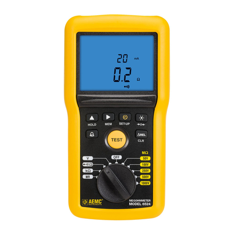
AEMC 1030 User manual

DIGITAL / ANALOG
MEGOHMMETERS
1030
1040
1045
ENGLISH User Manual

Statement of Compliance
Chauvin Arnoux®, Inc. d.b.a. AEMC®Instruments
certifies that this instrument has been calibrated
using standards and instruments traceable to
international standards.
We guarantee that at the time of shipping your
instrument has met its published specifications.
An NIST traceable certificate may be
requested at the time of purchase, or obtained
by returning the instrument to our repair and
calibration facility, for a nominal charge.
The recommended calibration interval for this
instrument is 12 months and begins on the date of
receipt by the customer. For recalibration, please
use our calibration services. Refer to our repair
and calibration section at www.aemc.com.
Serial #: ________________________________
Catalog #: 2116.89/2116.92/2116.93
Model #: 1030/1040/1045
Please fill in the appropriate date as indicated:
Date Received: _________________________________
Date Calibration Due: _______________________
Chauvin Arnoux®, Inc.
d.b.a AEMC®Instruments
www.aemc.com

Table of Contents
1. INTRODUCTION ........................................................................ 3
1.1 International Electrical Symbols.....................................................4
1.2 DenitionofMeasurementCategories...........................................4
1.3 ReceivingYourShipment...............................................................4
1.4 OrderingInformation ......................................................................5
1.4.1 AccessoriesandReplacementParts ................................5
2. PRODUCT FEATURES ............................................................... 6
2.1 Description .....................................................................................6
2.2 ControlFeatures ............................................................................7
2.2.1 Model 1030........................................................................7
2.2.2 Model 1040........................................................................8
2.2.3 Model 1045........................................................................9
2.3 DisplayFeatures ..........................................................................10
2.3.1 LCDDisplaySymbols......................................................10
2.3.2 AnalogBargraph .............................................................10
2.3.3 DigitalDisplaySymbols...................................................10
2.4 ControlFeatures .......................................................................... 11
2.4.1 YellowPushButton.......................................................... 11
2.4.2 ALARMButton(Models1040/1045)................................ 11
2.4.3 CursorButton(Models1040/1045) ................................. 11
2.4.4 ScrollCursorButton(Models1040/1045) .......................12
2.4.5 BacklightButton(Models1040/1045) .............................12
2.4.6 TIMERPushButton(Model1045) ..................................12
2.5 MeasurementFunctions ..............................................................12
2.5.1 InsulationResistanceTesting ..........................................12
2.5.2 ContinuityTesting ............................................................14
2.5.3 ResistanceMeasurement(Models1040/1045)...............14
2.6 SpecialFunctions.........................................................................15
2.6.1 TurningON/OFF-BatteryLifeIndication ........................15
2.6.2 AutoOFFFunction ..........................................................15
2.6.3 BatteryAutoTest .............................................................16
2.6.4 Buzzer .............................................................................16
2.6.5 AlarmSetpoints(Models1040/1045) ..............................17

2.6.6 MeasurementLeadResistanceCompensation
(Models1040/1045)....................................................18
2.6.7 Timer (Model1045) .....................................................19
3. SPECIFICATIONS .................................................................... 20
3.1 ElectricalSpecications ...............................................................20
3.1.1 ReferenceConditions......................................................20
3.1.2 VoltageDetection ............................................................20
3.1.3 InsulationResistanceTesting ..........................................20
3.1.4 Continuity ........................................................................21
3.1.5 Resistance
(Model1040/1045)............................................21
3.1.6 Timer (Model1045) ..............................................................22
3.1.7 PowerSupply ..................................................................22
3.2 EnvironmentalSpecications.......................................................22
3.2.1 InuencingParameters ...................................................22
3.2.2 Limits ...............................................................................23
3.3 MechanicalSpecications............................................................23
3.4 SafetySpecications....................................................................23
3.5 ApplicationExamples...................................................................24
3.5.1 InsulationMeasurementsonInstallations .......................24
3.5.2 InsulationMeasurementsonCables ...............................24
3.5.3 InsulationMeasurementsonMotors ...............................25
4. OPERATION............................................................................. 26
4.1 Operation .....................................................................................26
4.2 InsulationResistanceTesting ......................................................26
4.3 ContinuityMeasurements ............................................................27
4.4 ResistanceMeasurements(Models1040/1045) .........................28
5. MAINTENANCE ....................................................................... 29
5.1 BatteryReplacement ...................................................................29
5.2 FuseReplacement.......................................................................29
5.3 Cleaning.......................................................................................30
5.4 Storage ........................................................................................30
RepairandCalibration.................................................................................31
TechnicalandSalesAssistance ..................................................................31
Limited Warranty .........................................................................................32
WarrantyRepairs.........................................................................................32

MegohmmeterModels1030/1040/1045
3
CHAPTER 1
INTRODUCTION
Warning
Thesesafetywarningsareprovidedtoensurethesafetyof
personnelandproperoperationoftheinstrument.
• Readtheinstructionmanualcompletelyandfollowallsafety
informationbeforeoperatingthisinstrument.
• Safetyistheresponsibilityoftheoperator!
• Testsaretobecarriedoutonlyonnon-energizedcircuits!
Checkforlivecircuitsbeforemakingresistancemeasure-
ments(safetycheck).
• TheMegohmmeterModels1030,1040and1045are
sourcesofhighvoltage,asisthesampleconnectedto
them.Allpersonsperformingorassistinginthetestsmust
employallsafetyprecautionstopreventelectricalshockto
themselvesandtoothers.
• AEMC®considerstheuseofrubberglovestobean
excellentsafetypracticeeveniftheequipmentisproperly
operatedandcorrectlygrounded.
• Whentestingcapacitancesamples,makesurethatthey
havebeenproperlydischargedandthattheyaresafe
totouch.Dielectricinsulationsamplesshouldbeshort-
circuitedforatleastvetimestheamountoftimetheywere
energized.
• Megohmmetersshouldneverbeusedinanexplosiveenvi-
ronment.
• Usetheleadssuppliedwiththemegohmmeters.Iftheyare
defectiveorworn,replacebeforetesting.
• Thisinstrumentcanbeusedoninstallationsratedfor300V,
CategoryII(CATII).

4
MegohmmeterModels1030/1040/1045
1.1 International Electrical Symbols
This symbol signifies that the instrument is protected by double or rein-
forced insulation.
This symbol on the instrument indicates a WARNING and that the operator
must refer to the user manual for instructions before operating the
instrument. In this manual, the symbol preceding instructions indicates that
if the instructions are not followed, bodily injury, installation/sample and
product damage may result.
Risk of electric shock. The voltage at the parts marked with this symbol may
be dangerous.
In conformity with WEEE 2002/96/EC
1.2 Definition of Measurement Categories
CAT I: Formeasurementsoncircuits not directlyconnectedtotheAC
supply wall outlet such as protected secondaries, signal level,
andlimitedenergycircuits.
CAT II: For measurements performed on circuits directly connected to
the electrical distribution system. Examples are measurements
onhouseholdappliancesorportabletools.
CAT III: For measurements performed in the building installation at
the distribution level such as on hardwired equipment in xed
installationandcircuitbreakers.
CAT IV: For measurements performed at the primary electrical supply
(<1000V) such as on primary overcurrent protection devices,
ripplecontrolunits,ormeters.
1.3 Receiving Your Shipment
Uponreceivingyourshipment,makesurethatthecontentsareconsistent
withtheorderinginformation.Notifyyourdistributorofanymissingitems.
Iftheequipmentappearstobedamaged,leaclaimimmediatelywiththe
carrierandnotifyyourdistributoratonce,givingadetaileddescriptionof
anydamage.Savethedamagedpackingcontainertosubstantiateyour
claim.Donotuseaninstrumentthatappearstobedamaged.

MegohmmeterModels1030/1040/1045
5
1.4 Ordering Information
Megohmmeter Model 1030................................................ Cat. #2116.89
Megohmmeter Model 1040................................................ Cat. #2116.92
Megohmmeter Model 1045................................................ Cat. #2116.93
All models include a soft carrying pouch, two 1.5m test leads (red and black), 2 alligator clips
(red and black), 1 black test probe, 6 batteries, and user manual.
Megohmmeter Model 1040 Field Kit ................................ Cat. #2117.30
Megohmmeter Model 1045 Field Kit ................................ Cat. #2117.31
Each kit is delivered with a eld case, two 1.5m test leads (red and black), 2 alligator clips
(red and black), 1 black test probe, 1 remote test probe, 6 batteries, and user manual.
1.4.1 Accessories and Replacement Parts
RemoteTestProbe.............................................................. Cat. #2118.97
SoftCarryingPouch ............................................................ Cat. #2119.02
Setof5Fuses,FastActing,600V,
0.63A1/4x11/4"(6.3x32mm)..........................................Cat. #2970.78
FieldCase(Waterproof) ...................................................... Cat. #2118.98
HandsFreeCarryingCase.................................................. Cat. #2118.99
ReplacementLeadSet
(2leads,probe,2alligatorclips).......................................... Cat. #2119.01
Order Accessories and Replacement Parts Directly Online
Check our Storefront at www.aemc.com/store for availability

6
MegohmmeterModels1030/1040/1045
CHAPTER 2
PRODUCT FEATURES
Theterm“continuity”isusedtodenearesistancemeasurementwitha
testcurrentofatleast200mA(withthemeasuredresistancelowerthan
20Ω)in accordance with the VDE0413 and IEC 61557standards,and
todistinguishitfroma resistance measurement performedwithalower
unspeciedtestcurrent.
2.1 Description
The Megohmmeters Model 1030, 1040 and 1045 are battery powered
digital insulation resistance testers. They are designed to measure
insulationresistance,continuity,voltage,andtomeasureresistance.
These megohmmeters are used to verify the safety state of electrical
installations,motors,cablesandotherinsulatedproducts.Themeasure-
mentacquisition,processinganddisplayingtechnologyaremanagedby
amicroprocessor.
The Models 1030, 1040 and 1045 offer many features such as:
• Automaticdetectionofpotentiallydangerousvoltages
• Protectionagainstexternalvoltagesurges
• Enhancedoperatorsafetythroughautomaticdischargeofthe
testedsample
• Automaticshutdowntooptimizethebatterylife
• LargeLCDdisplaywitheasytoreadsymbolsandindicatorsand,
dependingonthemodel,brightblueelectroluminescentback-
lighting
• Alarmprogrammingforquicktests
• Leadresistancecompensationforaccuratecontinuitymeasure-
ments
• DisplayofthedurationofthemeasurementforeasyDARandPI
measurements

MegohmmeterModels1030/1040/1045
7
2.2 Control Features
2.2.1 Model 1030
®
INSTRUMENTS
M
Ω
- 250V
M
Ω
- 500V
20Ω
MEGOHMMETER
MODEL 1030
OFF
1
2
3
4
Figure 1
1. Safetyterminals,Ø4mm
(marked“+”onRedand“-”)
2. Liquidcrystaldisplay(LCD)
3. Yellowtestbutton
(usedtotestinsulationresistance)
4. 4positionrotaryswitch:
OFF,MΩ -250V,MΩ -500V,20Ω
5. Batterycompartmentandstand(notshowninthedrawing)

8
MegohmmeterModels1030/1040/1045
2.2.2 Model 1040
1
2
3
4
20
Ω
M
Ω
- 500V
MΩ- 1000V
400 k
Ω
OFF
ALARM
®
INSTRUMENTS
MEGOHMMETER
MODEL 1040
Figure 2
1. Safetyterminals,Ø4mm(marked“+”onRedand“-”).Notetheinput
fortheremotetestprobe(3-pointjack)nexttothe“-”terminal.
2. Backlightliquidcrystaldisplay(LCD)withprimary(large)display
andsecondary(small)displayforalarmandtimerfeatures.
3. Yellowtestbutton(totestinsulationresistance),ALARM,selection
andscrollcursors ,,and backlightbuttons.
4. 5positionrotaryswitch:
OFF,MΩ-500V,MΩ-1000V,400kΩ,20Ω
5. Batterycompartmentandstand(standnotshowninthedrawing).

MegohmmeterModels1030/1040/1045
9
2.2.3 Model 1045
ALARM
TIMER
®
INSTRUMENTS
400 k
Ω
M
Ω
- 250V
M
Ω
- 500V
MΩ- 1000V
MEGOHMMETER
MODEL 1045
OFF
20
Ω
1
2
3
4
Figure 3
1. Safetyterminals,Ø4mm(marked“+”onRedand“-”).Notetheinput
fortheremotetestprobe(3-pointjack)nexttothe“-”terminal
2. Backlightliquidcrystaldisplay(LCD)withprimary(large)displayand
secondary(small)displayforalarmandtimerfeatures
3. Yellowtestbutton(totestinsulationresistance),ALARM,selection
andscrollcursors ,,and backlightbuttons
4. 6positionrotaryswitch:
OFF,MΩ-250V,MΩ-500V,MΩ-1000V,400kΩ,20Ω
5. Batterycompartmentandstand(standnotshowninthedrawing)

10
MegohmmeterModels1030/1040/1045
2.3 Display Features
2.3.1 LCD Display Symbols
Timeractive(TIMERmode)
ALARM AlarmONorprogramminginprogress
>Alarmtriggeredabovesetpoint
<Alarmtriggeredbelowsetpoint
Dangeroustestvoltagegenerated
Seetheusermanual
> 25V Voltageatterminals(nongenerated)>25V
Ω
Compensatedleadresistance
Buzzeractive
AutoOffdisabled(noautomaticshutdown)
Batterystatus
Ω
and Flashing:incorrectcompensationofleadresistance
2.3.2 Analog Bargraph
Insulation>2GΩ
Insulation<50kΩ
2.3.3 Digital Display Symbols
BAT Batterieslow–mustbereplaced
OL OverRange-OverLoad
- - - Insulation<50kΩat250V,<100kΩat 500V
or<200kΩat 1000V

MegohmmeterModels1030/1040/1045
11
2.4 Control Features
2.4.1 Yellow Push Button
Theyellowbuttonisonlyusedtoinitiatethetestvoltagewhenmeasuring
insulationresistance.Itisnotusedforvoltage,resistance,orcontinuity
tests.
Inanyfunctionsetting(exceptOFF),themegohmmeterisinthevoltage
modeandworksasavoltagetestertodetectifanyvoltageispresenton
thetestedsample.Ifavoltagegreaterthan25Visdetected,theyellowtest
buttonisdisabledandinsulationtestingisnotpossible.
Theyellowtestbuttonisonlyactiveaslongasitispressed,(exceptionin
theTIMERmode-theModel1045-whererstpress=ON,secondpress
=OFF).
2.4.2 ALARM Button (Models 1040/1045)
TheALARMbuttonisusedtoturnthealarmONandOFFforinsulation,
resistance,andcontinuitymeasurements.
Itisalsousedwiththe and selectioncursorbuttonstoadjustthealarm
setpoints.
2.4.3 Cursor Button (Models 1040/1045)
Whenprogrammingthealarmsetpoints,the cursorbuttonmakesthe
followingsymbolsashasfollows:
• themeasurementunit(ifapplicable),
• thethousandsdigit,
• thehundredsdigit,
• thetensdigit,
• theunitsdigit,
• thedecimalpoint,
• thealarmtrigger(aboveorbelowthesetting),
• anditthenreturnstothemeasurementunits.

12
MegohmmeterModels1030/1040/1045
2.4.4 Scroll Cursor Button (Models 1040/1045)
When programming the alarm setpoints, the scroll cursor is used to
scrollthroughthepossiblevaluesforeachparameter,whichashes:
• MΩor GΩforinsulation,kΩor Ωforresistance,forthemeasure-
mentunits,
• 1,2,3or_forthethousandsdigit,
• 0,1,2,3,4,5,6,7,8and9forthehundreds,tensandunits,
• “-.---”or“--.--”or“---.-”or“----”forthedecimalseparator,
• >or<foraboveorbelowthresholdtrigger.
2.4.5 Backlight Button (Models 1040/1045)
The button turnsthebacklightonandoff.Thebacklightwillautomati-
callyturnoffafteroneminute.Itmayalsobeturnedoffbypressingthe
buttonagainatanytime.
2.4.6 TIMER Push Button (Model 1045)
Thisbuttonisusedtoturnonoroffthetimedinsulationresistancemea-
surement.Itmaybepressedeitherbeforetheyellowtestbutton,orduring
theinsulationresistancetest.Ifpressedduringatimedtestitwillstopthe
measurement.
2.5 Measurement Functions
2.5.1 Insulation Resistance Testing
TherotaryswitchMΩpositionsdeterminetheinsulationresistancetesting
voltage.
Tests are to be carried out on non-energized circuits only!
• Voltage Detection (Safety Check)
Thisisanautomaticsafetyfeature.AssoonastheswitchisturnedtoaMΩ
positionandbeforetheyellowtestbuttonispressed,themegohmmeter
enters a voltage detection mode. It measures any voltage between the
testleadsandthesample.Thisisasafetychecktoensurethatthetested
sampleisnotlive.

MegohmmeterModels1030/1040/1045
13
If the voltage detected is less than 25V,testingmaycontinue,butan
errormay occur.The lowerthetest voltage (250V,500V or 1000V) the
greatertheerror.
If the voltage is greater than 25V,“ and>25V”aredisplayed.
Insulation resistance testing is disabled. Pressing the yellow button will
onlycausethebuzzertoturnonandthe symboltoash.
Do not perform measurements if any voltage is present.
The warnings turn off only if the voltage at the terminals falls below
25V(removalofthetestleadsfromthesampleordisappearanceofthe
voltage),oriftheinstrumentisturnedOFF.
• Insulation Resistance Testing
AssoonastheswitchisturnedtoaMΩposition,themegohmmeterenters
avoltagedetectionmode(safetycheck).Itchecksifthereisanyvoltage
betweenthetestleadsandthesample.Thisisasafetychecktoensure
thatthetestedsampleisnotlive.(seeabove).
Insulationresistancetestingisinitiatedbypressingtheyellowtestbutton.
Thehightestvoltageisthengenerated.Theinsulationresistancevalueis
displayedontheanalogbargraph(logscale)andonthedigitaldisplay.
Ifthemeasuredinsulationresistanceisgreaterthan2GΩ(2000MΩ),the
OLsymbolisdisplayedonthedigitaldisplayinsteadofavalue,andifthe
measurementisgreaterthan2GΩ,the symbollightsupontheright-
handsideofthebargraph.Similarly,ifthemeasuredinsulationresistance
islessthan50kΩat250V,100kΩat500V,or200kΩat1000V,thedigital
measurementdisplayindicates“---”,andifthemeasurementislessthan
50kΩ,onlythe symbollightsupontheleft-handsideofthebargraph.
As soon as the yellow button is released the test voltage is stopped
(except in TIMER mode where it needs to be pressed again), and the
megohmmeter returns to the voltage test mode (safety check). It may
continue to display the voltage, due to the possibly charged sample.
The voltage may drop off more or less rapidly based on the sample
capacitance.
When the test voltage is generatedthe symbolisdisplayedtowarn
theuserthatthegeneratedtestvoltagemaybedangerous.

14
MegohmmeterModels1030/1040/1045
Note (Models 1040/1045):Aprogrammedalarmsettingmaybetriggered
(seepg17)duringthemeasurement.
Note (Model 1045):Themeasurementmaybetimed(see§2.6.7).
2.5.2 Continuity Testing
Tests are to be carried out on non-energized circuits only!
Continuity measurement corresponds to the “20Ω” rotary switch posi-
tion.ThemegohmmetertakesameasurementatI≥200mA,andtheΩ
symbolisdisplayed.WhentheALARMisactiveandthebuzzerturnedon,
thebuzzerwillsoundbeforethemeasurementvalueisdisplayed.Ifthe
resistanceisgreaterthan20Ω,OLisdisplayedonthedigitaldisplay.The
bargraphisnotactiveinthecontinuitymode.
Duringcontinuitytesting,thefuseischeckedautomaticallyafter
eachmeasurement.
Note (Models 1040/1045):Theresistanceofthemeasurementleadsmay
becompensated.Thealarm may be activeinthe continuity mode (see
§2.6.5).
Note (Model 1030):Inthecontinuitymode,aloweralarmpointof2Ωis
constantlyactive.Thebuzzerwillsound belowthisvalue.However,the
buzzermaybedisabledbypressingtheyellowbutton.
2.5.3 Resistance Measurement (Models 1040/1045)
Measurements to be carried out on non-energized circuits only!
Resistancemeasurementcorrespondstothe400kΩpositionoftherotary
switch.TheΩsymbolisdisplayedwiththekmultipliersymbolifneces-
sary.Themeasurementvalueisshownonthedigitaldisplay.
If the resistance is greater than 400kΩ, OL is displayed on the digital
display.Thebargraphisnotactiveinthecontinuitymode.
Thealarmmaybeactiveinresistancemeasurementmode.

MegohmmeterModels1030/1040/1045
15
2.6 Special Functions
2.6.1 Turning ON/OFF - Battery Life Indication
When you move the rotary switch from the OFF position to one of the
function positions, the battery voltage is applied to the circuit. The
instrumentturnson,andallofthedisplaylightsupatthesametimefor1
second.Thenfor2seconds,the symbolstayson,andthebargraph
and the digital display indicate the remaining battery life in percentage
(0to100%,e.g.0.95=95%).
Note, that this is approximate and based on a typical battery with total
voltagevaryingfrom6.7to10V.
Theinstrumentmaybeturnedoffatanytimebyturningtherotaryswitch
toOFF.Thiscutsoffthebatterypowersupplytothewholeinstrument.
2.6.2 Auto OFF Function
After5minuteswithoutanyoperationtotheinstrument(buttonpressed,
or on the remote control test probe, or turn of the rotary switch), the
instrumentautomaticallyentersastand-bymode.
To start up the instrument again do one of the following:
• Pressanyoneofthebuttons
• Turntheswitch
• Presstheyellowtestbuttonontheremotecontroltestprobe
TheAutoOFFisdisabledwhenmeasuringcontinuity,foraslongasthe
test current varies from zero (which means that a measurement is in
progress).
On the Model 1045, in the TIMER mode (see §2.6.7), the ve minutes
steadystatebeginsattheendofthemaximum15-minutemeasurement
period.
• Disabling/Enabling the Auto OFF (Models 1040/1045)
TodisabletheAutoOFF,keepthe buttonpresseddownwhenturning
ONtheinstrument.The symbolisthendisplayed,indicatingthatthe
AutoOFFfunctionhasbeendisabled.
ToenabletheAutoOFFfunction,turntheinstrumentoff(turntheswitchto
OFF)andthenturnitbackonagain.AutoOFFisthedefaultmode.

16
MegohmmeterModels1030/1040/1045
2.6.3 Battery Auto Test
Thebatterysupplyvoltageismeasuredautomaticallyeverysecond.The
batteryvoltagerangeforcorrectoperationis7Vto10V.
Therearefourpossiblecases:
• The voltage is correct: Nothingisdisplayed.
• The voltage < 7.1V:The symbolashes.Remainingbattery
lifeislimited.
• The voltage < 6.9V: The symbolremainslit.Measurement
accuracyisnolongerassured.Replacethebatteries.
• The voltage is close to 6.7V:Thedigitaldisplayindicates“BAT”
andthen,after5seconds,theshutdownbuzzersounds,andthe
AutoOFFfunctionisactivated.Theinstrumentshutsdown.
2.6.4 Buzzer
• The Different Sounds
Whenthe symbolisdisplayed,thebuzzerisactiveandgivesoutdiffer-
entsounds,dependingontheoperationorwarning.
• Short buzz (65 ms at 2kHz):
- pushonabutton
- autoOFF
- leadresistancecompensation
- after30s,1minand10minduringTIMEDinsulationresis-
tancemeasurement(Model1045)
• Continuous buzz (at 2kHz):
- measurementislowerthantheminimumsetpoint
- measurementishigherthanthemaximumsetpoint
• Short, higher buzz (65 ms at 4kHz):
- whenadisabled(inactive)buttonispressed
(excepttheyellowtestbutton)
• Repeated high buzzes (at 4kHz):
- thedetectedvoltage(safetycheck)atthesampleisgreater
than25V,andtheuserpressestheyellowtestbutton

MegohmmeterModels1030/1040/1045
17
• Disabling/Enabling the Buzzer
Model 1030: to disable the buzzer, turn the rotary switch to continuity
measurement(20Ω),andthenpresstheyellowtestbutton.Thebuzzer
soundsandthebuzzersymbolturnsoff.Toenablethebuzzer,pressthe
yellowtestbuttonagain,orturnswitchtoOFFandthenbackonagain.
Buzzeronisthedefaultmode.
Models 1040 and Model 1045: todisablethebuzzer,keeptheALARM
buttonpresseddownandturntheinstrumentON.Thebuzzersymbolisoff
(notlit).Toenablethebuzzer,turnswitchtoOFFandthenbackonagain.
Buzzeronisthedefaultmode.
2.6.5 Alarm Setpoints (Models 1040/1045)
Alarmsetpointsarefullyprogrammableforeachfunction.Therecanbe
analarmsetpointforeachmeasurementfunction.Thesetpointscanbe
upperorlowerthresholds.Theycanbeactiveorinactive,andwillbekept
inmemoryevenaftertheinstrumenthasbeenturnedoff.
• Programming of the Alarm Setpoints
To program the setpoint press the ALARM button until the “ALARM”
symbolisdisplayedandbeepsasecondtime(thesetpointunitwillblink,
e.g.MΩ).Thevalueofthesetpointcorrespondingtotheselectedrangeis
indicatedonthesmalldigitaldisplay.
The display indicates the following default setpoints settings:
• >0.25MΩfortheMΩ-250Vposition
• >0.50MΩfortheMΩ-500Vposition
• >1.00MΩfortheMΩ-1000Vposition
• <10.00kΩforthe400kΩposition
• <2.00Ωforthe20Ωposition
Thesetpointsmaybeprogrammedusingthecursorbuttons(see§2.4.3).
Duringprogramming,themegohmmetercontinuesmeasuring.
Tosavethesetpointsintomemory,quittheprogrammingmodebyanother
longpressontheALARMbuttonuntilthesecondbeep.
There are limitations on the value of the setpoints.Iftheprogrammed
setpoint is too high, it is corrected when it is stored into memory: the
maximumrangevaluewillbeentered.Forexample,forcontinuitymea-
surements, a 30.00Ω setpoint will be stored as 20.00Ω (max value for
continuity).
If the setpoint has been improperly input, it is also corrected when it is
storedintomemory:Forexample,002MΩwillbecome2.00MΩ.

18
MegohmmeterModels1030/1040/1045
• Turning the Alarm ON and OFF
TheAlarmcanbeturnedONbyashortpressontheALARMbutton.The
buzzerbeepsandtheALARM symbol, the < or > symbol, and the pro-
grammedsetpointvalueisthendisplayedonthedigitalsetpointdisplay.
TheAlarmcanbeturnedOFFbyasecondshortpress(andonebeep)on
theALARMbutton.TheALARMsymbol,the<or>symbol,andthealarm
setpointwilldisappear.
• Triggering the Alarm
Whena setpoint is reached andthealarm is turned on, the buzzerwill
soundcontinuouslyandtheALARMandthesettingswillash.
Forexample,when measuringcontinuitywithasetpoint withavalueof
>10Ω,theinstrumentdisplays“ALARM>10.00Ω”whenthealarmison.
Ifthemeasurementexceeds10.00Ω,acontinuousbeepwillbetriggered
andthealarmdisplaywillash.
Similarly,ifwhenmeasuringinsulationwithasetpointvalueof<10MΩ,the
instrumentdisplays“ALARM<10.00MΩ”.Ifthemeasurementfallsbelow
thisvalue,acontinuousbeepwillbetriggeredandthealarmdisplaywill
ash.
2.6.6 Measurement Lead Resistance Compensation
(Models 1040/1045)
Testleadresistancemaybeimportantinacontinuitymeasurement,and
removing this resistance improves the measurement accuracy of low
resistances. The lead resistance compensation feature is only active in
thecontinuitymeasurementmode(20Ω).
To compensate (offset) the test leads resistance, short-circuit the leads
andpressthe buttonforashorttime(longpress).Whenthecompensa-
tionhasbeenrecorded,thedisplayindicates0.00andthebuzzersounds.
Fromthismomenton,themeasurementsdisplayedwillbeautomatically
reducedbythevaluerecordedandthe
Ω
symbolwilldedisplayed.
To delete the compensated lead resistance, remove the test leads and
pressthe buttonforashorttime(longpress).Whentheleadcompen-
sationiscancelled,the
Ω
symbolgoesout.Notethatthemaximum20Ω
continuity measurement range is reduced by the stored compensation
value.
Other manuals for 1030
1
This manual suits for next models
2
Table of contents
Other AEMC Multimeter manuals