AEMC 5231 User manual

DIGITAL MULTIMETER
with Non-Contact Detection
5231
ENGLISH User Manual

Statement of Compliance
Chauvin Arnoux®, Inc. d.b.a. AEMC®Instruments
certifies that this instrument has been calibrated
using standards and instruments traceable to
international standards.
We guarantee that at the time of shipping your
instrument has met its published specifications.
An NIST traceable certificate may be
requested at the time of purchase, or obtained
by returning the instrument to our repair and
calibration facility, for a nominal charge.
The recommended calibration interval for this
instrument is 12 months and begins on the date of
receipt by the customer. For recalibration, please
use our calibration services. Refer to our repair
and calibration section at www.aemc.com.
Serial #: ________________________________
Catalog #: 2125.64
Model #: 5231
Please fill in the appropriate date as indicated:
Date Received: _________________________________
Date Calibration Due: _______________________
Chauvin Arnoux®, Inc.
d.b.a AEMC®Instruments
www.aemc.com

Digital Multimeter Model 5231
1
Table of Contents
1. INTRODUCTION............................................................................... 3
1.1 International Electrical Symbols................................................4
1.2 DenitionofMeasurementCategories .....................................4
1.3 Receiving Your Shipment..........................................................5
1.4 OrderingInformation.................................................................5
1.4.1 Accessories and Replacement Parts............................5
2. PRODUCT FEATURES ...................................................................... 6
2.1 Description................................................................................6
2.2 Control Features .......................................................................7
2.3 Display Features.......................................................................8
2.4 Button Functions.......................................................................8
2.5 Rotary Functions.......................................................................9
3. OPERATION .................................................................................. 10
3.1 Turning the Multimeter ON......................................................10
3.2 Turning the Multimeter OFF....................................................10
3.3 Activating/Deactivating Auto-OFF...........................................10
3.4 Auto and Manual Range Selection .........................................10
3.5 Non-Contact Voltage (NCV)....................................................11
3.6 Voltage Measurement.............................................................11
3.7 Resistance Measurement .......................................................12
3.8 Continuity Test ........................................................................13
3.9 Diode Test...............................................................................14
3.10 Current Measurement Using a Clamp-on Probe ....................15
4. MAINTENANCE ............................................................................. 16
4.1 Warning...................................................................................16
4.2 Battery Replacement ..............................................................16
4.3 Cleaning..................................................................................16

2
Digital Multimeter Model 5231
5. SPECIFICATIONS........................................................................... 17
Repair and Calibration...........................................................................19
Technical and Sales Assistance ............................................................19
Limited Warranty ...................................................................................20
Warranty Repairs...................................................................................20

Digital Multimeter Model 5231
3
CHAPTER 1
INTRODUCTION
Warning
This device complies with safety standard IEC-61010-1 (Ed
2–2001)forvoltagesupto1000VCATIIIor600VCATIV,atan
altitudebelow 2000m,indoors,with apollutionlevel ofnotmore
than 2.
Failure to observe the safety instructions may cause an electric
shock,re,explosion,ordestructionoftheinstrumentandofthe
installations.
• Donotusetheinstrumentinanexplosiveatmosphereorin
thepresenceofammablegasesorfumes.
• Donotusetheinstrumentonnetworksofwhichthevoltage
orcategoryexceedsthosementioned.
• Donotexceedtheratedmaximumvoltagesandcurrents
between terminals or with respect to earth/ground.
• Donotusetheinstrumentifitappearstobedamaged,
incomplete,ornotproperlyclosed.
• Beforeeachuse,checktheconditionoftheinsulationonthe
leads,housing,andaccessories.Anyelementofwhichthe
insulationisdeteriorated(evenpartially)mustbesetasidefor
repair or scrapped.
• Useleadsandaccessoriesratedforvoltagesandcategories
atleastequaltothoseoftheinstrument.
• Observetheenvironmentalconditionsofuse.
• Donotmodifytheinstrumentanddonotreplacecomponents
with “equivalents”. Repairs and adjustments must be done by
approvedqualiedpersonnel.
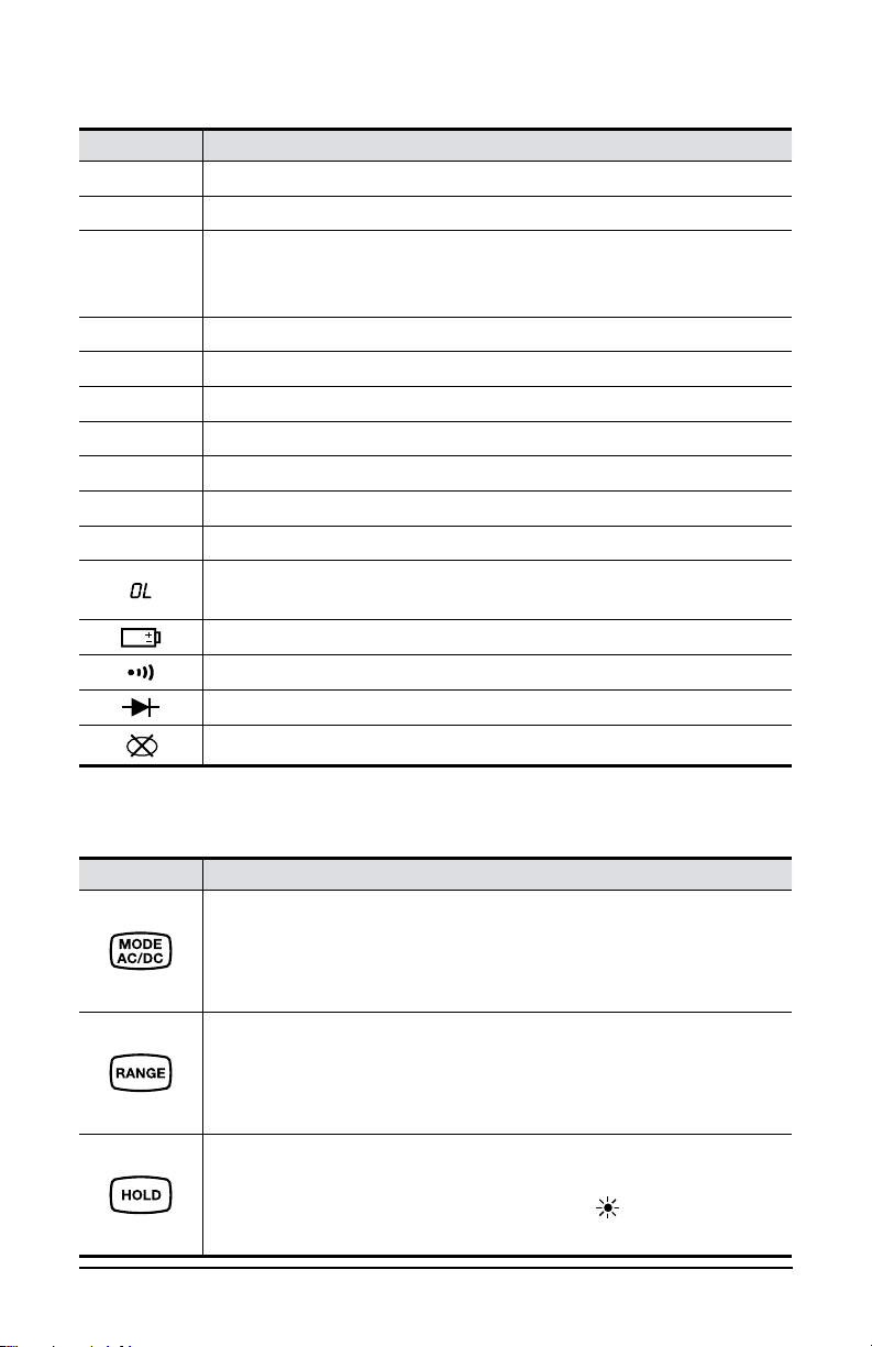
• Replace the battery as soon as the symbol appears
onthedisplayunit.Disconnectallleadsbeforeopeningthe
battery compartment cover.
• Use personal protective equipment when conditions require.
• Keepyourhandsawayfromunusedterminalsoftheinstrument.
• Whenhandlingprobesorcontacttips,keepyourngers
behind the guards.

4
Digital Multimeter Model 5231
1.1 International Electrical Symbols
Signifies that the instrument is protected by double or reinforced insulation.
This symbol on the instrument indicates a WARNING that the operator must
refer to the user manual for instructions before operating the instrument. In
this manual, the symbol preceding instructions indicates that if the instructions
are not followed, bodily injury, installation/sample and/or product damage may
result.
Compliance with the Low Voltage & Electromagnetic Compatibility European
directives (73/23/CEE & 89/336/CEE)
AC – Alternating current
AC or DC – Alternating or direct current
Risk of electric shock. The voltage at the parts marked with this symbol may be
dangerous.
Important instructions to read and understand completely.
Important information to acknowledge.
Ground/Earth symbol
In conformity with WEEE 2002/96/EC
1.2 Definition of Measurement Categories
CAT I: For measurements on circuits not directly connected to the AC
supplywalloutletsuchasprotectedsecondaries,signallevel,and
limited energy circuits.
CAT II: For measurements performed on circuits directly connected to
the electrical distribution system. Examples are measurements on
household appliances or portable tools.
CAT III:
Formeasurementsperformedinthebuildinginstallationatthedistri-
butionlevelsuchasonhardwiredequipmentinxedinstallationand
circuit breakers.
CAT IV: For measurements performed at the primary electrical supply
(<1000V)suchasonprimaryovercurrentprotectiondevices,ripple
controlunits,ormeters.

Digital Multimeter Model 5231
5
1.3 Receiving Your Shipment
Uponreceivingyourshipment,makesurethatthecontentsareconsistent
withthepackinglist.Notifyyourdistributorofanymissingitems.Iftheequip-
mentappearstobedamaged,leaclaimimmediatelywiththecarrierand
notifyyourdistributoratonce,givingadetaileddescriptionofanydamage.
Save the damaged packing container to substantiate your claim
.
1.4 Ordering Information
Multimeter Model 5231......................................................Cat. #2125.64
Includes set of two 5 ft color-coded leads (red/black) with needle tip {CAT IV 1000V
15A), soft carrying case and a user manual.
1.4.1 Accessories and Replacement Parts
Case - Replacement Carrying Pouch ................................. Cat. #2125.87
Lead-ReplacementSetof2,5ftColor-Coded(Red/Black)
with needle tip {CAT IV 1000V 15A) ..................................Cat. #2152.21
Order Accessories and Replacement Parts Directly Online
Check our Storefront at www.aemc.com for availability

6
Digital Multimeter Model 5231
CHAPTER 2
PRODUCT FEATURES
2.1 Description
TheModel5231isaTRMSdigitalmultimeter,speciallydesignedtocom-
binethevariousfunctionsand measurements ofthe following electrical
quantities:
• Non-contactdetectionofpresenceofnetworkvoltage
(NCVfunction)
• AC voltmeter with low input impedance (voltage measurements
forelectricityandelectricalengineering)
• AC/DC voltmeter with high input impedance
(voltagemeasurementsforelectronics)
• Ohmmeter
• Continuity test with buzzer
• Diode test
• Ammeter (measurement using current clamp-on probe)

Digital Multimeter Model 5231
7
2.2 Control Features
AUTO
mVA
MkΩ
AC DC
HOLD
0600
100 500
200 400300
P
2
1
3
4
5
Figure 2-1
1. NCV detection sensor (see § 3.5)
2. Analog and digital display (see § 2.3)
3. Function buttons (see § 2.4)
4. Rotary switch (see § 2.5)
5. Positive (Red) input and COM (Black) input

8
Digital Multimeter Model 5231
2.3 Display Features
Icon Function
AC Alternating Current
DC Direct Current
AUTO
The Automatic Range symbol indicates that the
instrument will automatically adjust to the correct
measurement range when taking the measurement
HOLD Freezes the display of the measurement
mPrefix “mili”
VVoltage
AAmpere
MPrefix “Mega”
kPrefix “kilo”
WOhm
The Overload symbol is displayed when the signal measured exceeds
the range of the device
Low Battery
Continuity Beeper Enabled
Diode Test
P
Auto Power OFF function activated
2.4 Button Functions
Button Function
• Measurement type selection
NOTE: The DC mode is activated by default
• Activates/Deactivates the Auto-OFF function at start-up
(see § 3.3)
• Allows manual selection of a measurement range
(short press)
• Returns to Auto-Range mode (long press > 2s)
NOTE: Continuity and Diode modes are not Auto-ranging
• Freezes/Unfreezes the display of the measured value
(short press)
• Activates/Deactivates the display backlight
(long press > 2s)

Digital Multimeter Model 5231
9
2.5 Rotary Functions
Range Function
OFF Powers down the multimeter
Low impedance AC voltage measurement
AC or DC voltage measurement (V)
AC or DC voltage measurement (mV)
Resistance measurement
Continuity test
Diode test
Current measurement with AC or DC clamp, ratio 1mV/A
NCV (Non-contact Voltage) + Partial OFF mode of the multimeter
(NCV function active)

10
Digital Multimeter Model 5231
CHAPTER 3
OPERATION
3.1 Turning the Multimeter ON
Turntheswitchtotheappropriatefunction.Allsegmentsofthedisplaywill
lightforafewseconds.Thescreencorrespondingtothechosenfunction
willthenappear.Themultimeterisnowreadyformeasurements.
3.2 Turning the Multimeter OFF
Toturnthemeteroffmanually,turntheswitchtoOFF.Ifleftunusedfor
15minutes,themeterwillturnoffautomatically.At14minutes,vebeeps
warnthatthemeterisabouttobeturnedoff.Toturnbackon,pressany
button on the unit.
NOTE: The position does not completely turn the multimeter off.
It remains active for non-contact detection of the presence of network
voltage (NCV).
3.3 Activating/Deactivating Auto-OFF
Bydefault,Auto-OFFisactivatedandthe
P
symbol is displayed.
A long press on the buttonduringstart-up,whileturningtheswitch
toanyrange,deactivatestheAuto-OFFfunction.The
P
symbol is not
displayed.
3.4 Auto and Manual Range Selection
By default, the meter is in auto-range. This is indicated by the AUTO
symbolonthedisplay.Whileon,theinstrumentwillautomaticallyadjustto
the correct measurement range when taking the measurement.
TochangetherangeselectiontoManual,pressthe button.

Digital Multimeter Model 5231
11
3.5 Non-Contact Voltage (NCV)
• Turn the rotary switch to the NCV position.
• Move the Model 5231 (NCV detection sensor) close to the
potentiallyliveconductor(s)(presenceofphase).
Ifanetworkvoltageof90Vorgreaterispresent,theback-lightinglightsup
red,otherwise,itremainsoff.
3.6 Voltage Measurement
The Model 5231 measures AC voltage at low input impedance (VLOWZ),
DC and AC voltages.
• Set the switch to , ,or . When set to the
device is in AC mode only.
• For or ,selectACorDCbypressing .Bydefault
the meter is in DC mode.
• Insert the red lead to the red “+” input jack and the black lead to
the black “COM” input jack.
• Connect the test probe tips to the sample under test.
Figure 3-1

12
Digital Multimeter Model 5231
3.7 Resistance Measurement
WARNING: When making a resistance measurement, make sure that
the power is off (de-energized circuit). It is also important that all
capacitors in the measured circuit be fully discharged.
• Turn the rotary switch to the position.
• Insert the red lead to the red “+” input jack and the black lead to
the black "COM" input jack.
• Connect the test probe tips to the sample under test.
Figure 3-2

Digital Multimeter Model 5231
13
3.8 Continuity Test
WARNING: When making a resistance measurement, make sure that
the power is off (de-energized circuit).
• Turn the rotary switch to the position.
• Press the button. The symbol is displayed.
• Insert the red lead to the red “+” input jack and the black lead to
the black "COM" input jack.
• Connect the test probe tips to the sample under test.
• The buzzer sounds when the circuit to be checked is DC or has
aresistanceoflessthan100Ω±3Ω.
Figure 3-3

14
Digital Multimeter Model 5231
3.9 Diode Test
WARNING: When making a diode measurement, make sure that the
power is off (de-energized circuit).
• Turn the rotary switch to the position.
• Press the button twice. The symbol is displayed.
• Insert the red lead to the red “+” input jack and the black lead to
the black “COM” input jack.
• Connect the test probe tips to the sample under test.
Figure 3-4

Digital Multimeter Model 5231
15
3.10 Current Measurement Using a Clamp-on Probe
• Turn the rotary switch to the position.
• Select AC or DC by pressing the button.Bydefaultthe
meterisinACmode.Dependingontheselection,thescreen
displays AC or DC.
• Insert the current probe’s red lead to the red “+” input jack and
the black lead to the black “COM” input jack.
• Clamp the current probe around the current carrying conductor
to be tested.
Figure 3-5

16
Digital Multimeter Model 5231
CHAPTER 4
MAINTENANCE
4.1 Warning
• Removethetestleadsfromanyinputbeforeopeningthecase.Donot
operate the instrument without a battery case cover.
• To avoid electrical shock, do not attempt to perform any servicing
unlessyouarequaliedtodoso.
• If the meter is not going to be used for a long period of time, take
out the batteries. Do not store the meter in high temperatures or high
humidity.
• Toavoidelectricalshockand/ordamagetotheinstrument,donotget
waterorotherforeignagentsintotheprobe.
4.2 Battery Replacement
• Thebatterieswillneedtobereplacedwhenthe symbol appears
on the display.
• The meter must be in the OFF position and disconnected from any
circuit or input.
• Usingascrewdriver,unscrewthefourscrewsofthebatterycompart-
mentcoveronthebackofthehousing.
• Replacetheoldbatterywithonenew9Vbattery,observingthepolarity.
• Replacethebatterycompartmentcoverandtightenthescrews.
4.3 Cleaning
• DisconnectallleadsfromtheinstrumentandsettheswitchtoOFF.
• To clean the instrument, wipe the case with a damp cloth and mild
detergent. Do not use abrasives or solvents. Dry thoroughly before
use.
• Donotgetwaterinsidethecase.Thismayleadtoelectricalshockor
damage to the instrument.

Digital Multimeter Model 5231
17
CHAPTER 5
SPECIFICATIONS
Reference Conditions: Accuracy given @ 23°C ± 2°C; Relative Humidity 45 to 75%; Supply Voltage 8.5V ± 0.5V
ELECTRICAL
DC (mVDC) 60mV 600mV
Resolution 0.01mV 0.1mV
Accuracy (±) 1% + 12cts 0.6% + 2cts
Input Impedance 10MW
DC (VDC) 600mV 6V 60V 600V 1000V
Resolution 0.1mV 0.001V 0.01V 0.1V 1V
Accuracy (±) 06% + 2cts 0.1% + 2cts 0.15% + 2cts
Input Impedance 10MW
AC (mVAC TRMS) 60mV 600mV
Resolution 0.01mV 0.1mV
Accuracy (±)
40 to 60Hz 1% + 12cts 1 % + 3cts
Accuracy (±)
60Hz to 1kHz 1% + 12cts 2% + 3cts
Input Impedance 10MW
AC (VAC TRMS) 6V 60V 600V 1000V
Resolution 0.001V 0.01V 0.1V 1V
Accuracy (±)
40 to 60Hz 1% + 3cts 2% + 3cts
Accuracy (±)
60Hz to 1kHz 2.5% + 3cts 2% + 3cts 2.5% + 3cts
Input Impedance 10MW
AC (VAC LowZ TRMS)* 6V 60V 600V 1000V
Resolution 0.001V 0.01V 0.1V 1V
Accuracy (±)
40 to 60Hz 2% + 1ct
Input Impedance 270kW
*NOTE: A low input impedance serves to eliminate the effects of interference voltages due to the
supply network, and makes it possible to measure an AC voltage with a minimum of error.

18
Digital Multimeter Model 5231
ELECTRICAL
Resistance 600W6kW60kW600kW6MW60MW
Resolution 0.1W0.001kW0.01kW0.1kW0.001MW0.01MW
Accuracy (±) 2% + 2cts 0.3% + 4cts 0.5% + 20cts
Continuity Test 600W
Resolution 0.1W
Measurement
Current < 0.35mA
Accuracy (±) Audible signal < 100W+ 3W
Diode Test 2.8V
Resolution 0.001V
Open-circuit
Voltage < 2.8V
Measurement
Current < 0.9mA
Accuracy (±) 1% + 2cts
AC/DC Current (with clamp having a ratio of 1mV/1A)
Range 600A
Resolution 0.1A
Accuracy (±) 40Hz to 1kHz; 2.0% + 2cts*
Power 9V (6LR61) alkaline battery
Battery Life > 100 hours
Auto Power OFF Automatic shut down after 15 minutes of no use
ENVIRONMENTAL
Operating Temp. 32° to 122°F (0° to 50°C)
Storage Temp. -4° to 158°F (-20° to 70°C)
Operating RH ≤90% at 104°F (40°C)
Storage RH ≤50% at 140°F (60°C)
MECHANICAL
Dimension 6.1 x 2.95 x 2.17" (155 x 75 x 55mm)
Weight 11 oz (320g) with battery
Measurement
Acquisition 3 times per second
Bargraph 61 segments, refresh interval 30ms
SAFETY
Safety Rating IEC/EN 61010-1, 1000V CAT III, 600V CAT IV; Pollution Degree 2
Double Insulated Yes
Electro-magnetic
Compatibility EN-61326/A2:2001
Drop Test 1m (in accordance with standard IEC-68-2-32)
Case Protection IP54 as per EN 60529
CE Yes
*Not including current clamp sensor accuracy
Table of contents
Other AEMC Multimeter manuals