AEMC 401 User manual

401
CLAMP-ON METER
User ManualENGLISH

2

3
CONTENTS
RECEIVING YOUR SHIPMENT...........................................................................7
ORDERING INFORMATION................................................................................7
1 PRESENTATION..........................................................................................8
1.1 THEROTARYSWITCH...................................................................................9
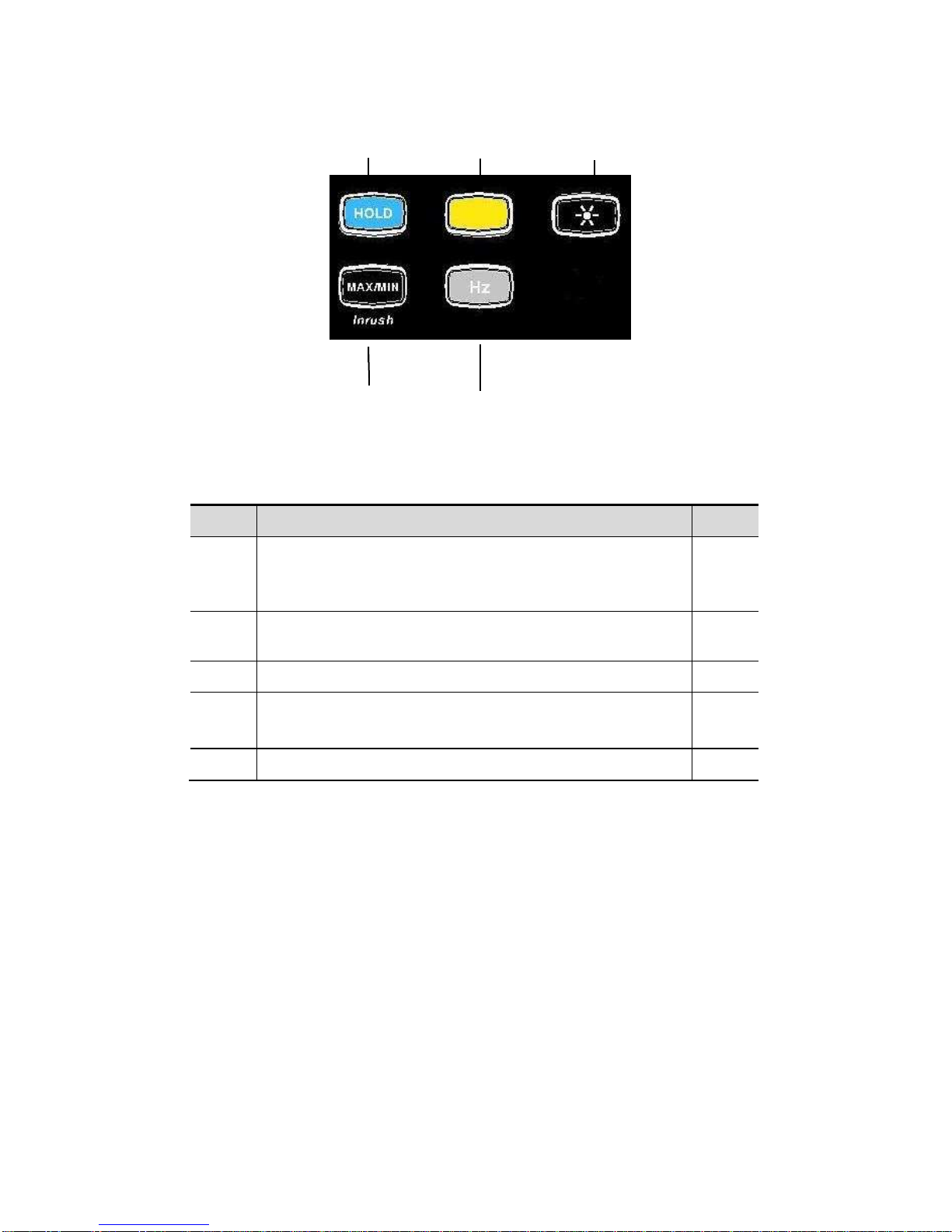
1.2 THEFUNCTIONBUTTONS..........................................................................10
1.3 THEDISPLAY ................................................................................................11
1.3.1 Display Symbols ...........................................................................11
1.3.2 Measurement Capacity Exceeded (OL)........................................12
1.4 THETERMINALS...........................................................................................12
2 THE BUTTONS........................................................................................... 13
2.1 BUTTON.................................................................................................13
2.2 (YELLOW)BUTTON(SECOND FUNCTION)..............................................14
2.3 BUTTON................................................................................................14
2.4 BUTTON..............................................................................................15
2.4.1 Normal Mode ................................................................................15
2.4.2 The MAX/MIN Mode + Activation of the HOLD Mode................... 16
2.4.3 Access to the True Inrush™Mode ( set to )................16
2.5 BUTTON................................................................................................17
2.5.1 Normal Mode ................................................................................17
2.5.2 The Hz Function + Activation of the HOLD Mode .........................17
3 USE............................................................................................................. 18
3.1 INSTALLINGTHEBATTERIES ....................................................................18
3.2 TURNINGTHECLAMP-ONMETERON......................................................18
3.3 TURNINGTHECLAMP-ONMETEROFF....................................................18
3.4 CONFIGURATION.........................................................................................19
3.4.1 Configuring the Maximum Resistance for Continuity ....................19
3.4.2 Auto Power OFF...........................................................................19
3.4.3 Configuring the Threshold for True InRush™Measurement.........19
3.4.4 Changing the Default Temperature Unit .......................................20
3.4.5 Default Configuration.................................................................... 21
3.5 VOLTAGEMEASUREMENT(V)...................................................................21
3.6 CONTINUITYTEST .................................................................................22
3.6.1 Lead Resistance Compensation...................................................22
3.7 RESISTANCEMEASUREMENT..............................................................23
3.8 DIODETEST ............................................................................................23
3.9 CURRENTMEASUREMENT(A)..................................................................24
3.9.1 AC Measurement..........................................................................24
3.10 STARTINGCURRENTOROVERCURRENT(True InRush™)
MEASUREMENT.......................................................................................................25
3.11 FREQUENCYMEASUREMENT(HZ)...........................................................25

4
3.11.1 Frequency Measurement (V) ........................................................ 25
3.11.2 Frequency Measurement (A) ........................................................ 26
3.12 TEMPERATUREMEASUREMENT..............................................................27
3.12.1 Measurement without External Sensor.........................................27
3.12.2 Measurement with External Sensor..............................................27
4 SPECIFICATIONS ...................................................................................... 28
4.1 REFERENCECONDITIONS.........................................................................28
4.2 SPECIFICATIONSUNDERTHEREFERENCECONDITIONS..................28
4.2.1 DC Voltage Measurement.............................................................28
4.2.2 AC Voltage Measurement.............................................................29
4.2.3 AC Current Measurement.............................................................29
4.2.4 True Inrush™Measurement.........................................................30
4.2.5 Continuity Measurement...............................................................30
4.2.6 Resistance Measurement .............................................................30
4.2.7 Diode test......................................................................................31
4.2.8 Frequency Measurements ............................................................ 31
4.2.9 Temperature Measurement...........................................................32
4.3 ENVIRONMENTALCONDITIONS ...............................................................32
4.4 MECHANICALSPECIFICATIONS ...............................................................33
4.5 POWERSUPPLY...........................................................................................33
4.6 COMPLIANCEWITHINTERNATIONALSTANDARDS..............................33
4.7 ENVIRONMENTALVARIATIONS................................................................34
5 MAINTENANCE.......................................................................................... 35
5.1 WARNING ......................................................................................................35
5.2 CLEANING .....................................................................................................35
5.3 REPLACEMENTOFTHEBATTERIES........................................................35
6 REPAIR AND CALIBRATION .................................................................... 36
7 TECHNICAL AND SALES ASSISTANCE.................................................. 36
8 LIMITED WARRANTY................................................................................ 37
9 WARRANTY REPAIRS .............................................................................. 37

5
Thank you for purchasing a Model 401 Clamp-on Meter.
For best results from your instrument and for your safety, read the enclosed
operating instructions carefully and comply with the precautions for use. These
products must be only used by qualified and trained users.
Meanings of the symbols used on the device
CAUTION - Risk of Danger!
Indicates a WARNING and that the operator
must refer to the user manual for instructions before operating the instrument
in all cases where this symbol is marked.
Risk of electric shock. The voltage at
the parts marked with this symbol may
be dangerous.
Refers to a type A current sensor. This symbol signifies that application
around and removal from HAZARDOUS LIVE conductors is permitted.
1.5 V battery
The CE marking indicates compliance with European directives
Double insulation or reinforced insulation
In the European Union, this product is subject to a separate collection system
for recycling electrical and electronic components In accordance with directive
WEEE 2002/96/EC
AC – Alternating current
AC and DC – Alternating and direct current
Ground/Earth

6
PRECAUTIONS FOR USE
This device complies with safety standards IEC-61010-1 and 61010-2-032 for voltages of
1000V in category IV at an altitude of less than 2000m, indoors, with a degree of pollution
not exceeding 2.
These safety instructions are intended to ensure the safety of persons and proper operation
of the device.
The operator and/or the responsible authority must carefully read and clearly
understand the various precautions to be taken in use.
If this instrument is used other than as specified, the protection it provides may be
compromised, thereby endangering you.
Do not use the instrument in an explosive atmosphere or in the presence of flammable
gases or fumes.
Do not use the instrument on networks of which the voltage or category exceeds those
mentioned.
Do not exceed the rated maximum voltages and currents between terminals or with
respect to earth.
Do not use the instrument if it appears to be damaged, incomplete, or not properly
closed.
Before each use, check the condition of the insulation on the leads, housing, and
accessories. Any element of which the insulation is deteriorated (even partially) must
be set aside for repair or scrapped.
Use leads and accessories rated for voltages and categories at least equal to those of
the instrument. If not, an accessory of a lower category lowers the category of the
combined Clamp + accessory to that of the accessory.
Observe the environmental conditions of use.
Do not modify the instrument and only use factory replacement parts. Repairs and
adjustments must be done by approved qualified personnel.
Replace the batteries as soon as the symbol appears on the display of the unit.
Disconnect all leads before opening the battery compartment cover.
Use personal protective equipment when conditions require.
Keep your hands away from the unused terminals of the instrument.
When handling the test probes, alligator clips, and clamp ammeters, keep your fingers
behind the physical guard.
As a safety measure, and to avoid repeated overloads on the inputs of the device,
configuration operations should only be performed when the device is disconnected
from all dangerous voltages.

7
MEASUREMENT CATEGORIES
Definitions of the measurement categories :
CAT II: Circuits directly connected to the low-voltage installation.
Example: power supply to household electrical appliances and portable tools.
CAT III: Power supply circuits in the installation of the building.
Example: distribution panel, circuit-breakers, fixed industrial machines or
devices.
CAT IV: Circuits supplying the low-voltage installation of the building.
Example: power lines, meters, and protection devices.
RECEIVING YOUR SHIPMENT
Upon receiving your shipment, make sure that the contents are consistent with the
packing list. Notify your distributor of any missing items. If the equipment appears
to be damaged, file a claim immediately with the carrier and notify your distributor
at once, giving a detailed description of any damage. Save the damaged packing
container to substantiate your claim.
ORDERING INFORMATION
Clamp-on Meter Model 401.......................................................... Cat. #2139.20
Includes set of 2 color-coded silicone insulated test leads, test probes and alligator clips,
K-thermocouple with 4mm integrated adapter, soft carrying case, 4x1.5V AA batteries and
user manual.
Replacement Parts:
K-thermocouple with 4mm Integrated Adapter................................................Cat. #2139.71
Soft Carrying Case.........................................................................................Cat. #2139.72
Set of 2 Color-coded Silicone Test Leads, Test Probes & Alligator Clips ........Cat. #2152.05

8
1
3
4
5
6
2
7
1 PRESENTATION
The Clamp-on Meter Model 401 is a professional electrical measuring instrument
that combines the following functions:
Current measurement
Measurement of True InRush™current / overcurrent
Voltage measurement
Frequency measurement
Continuity test with buzzer
Resistance measurement
Diode test
Temperature measurement
Item Designation See §
1Jaws with centering marks
(see connection principles) 3.5 to
3.12
2 Physical Guard -
3 Rotary Function Switch 1.1
4 Function Buttons 2
5 Backlit Display 1.3
6 Input Terminals 1.4
7 Trigger -
Figure 1: Clamp-on Meter Model 401

9
1.1 THE ROTARY SWITCH
The rotary switch has five positions. To access the , , , , functions,
set the switch to the desired function. The functions are described in the table
below.
Figure 2: The Function Rotary Switch
Item Function See §
1 OFF mode – Turns the clamp-on meter off 3.3
2 AC, DC voltage measurement (V) 3.5
3 Continuity test
Resistance measurement
Diode test
3.6
3.7
3.8
4 AC current measurement (A) 3.9
5 Temperature measurement (°C/°F) 3.12
1
2
3
4
5

10
1.2 THE FUNCTION BUTTONS
1 2 3
4 5
Figure 3: The Function Buttons
Item Function See §
1 Holds the last value on the display
Lead resistance compensation in the continuity and
ohmmeter functions
2.1
3.6.1
2 Selects the type of measurement and configuration
functions (AC, DC) 2.2
3 Enables/disables display backlighting 2.3
4 Enables/disables the MAX/MIN mode
Enables/disables the True InRush™mode 2.4
5 Performs Frequency measurements (Hz) 2.5

11
1.3 THE DISPLAY
7
Figure 4: The Display
Item Function See §
1 Mode selection display 2
2 Display of the measurement value and unit 3.5 to 3.12
3 Display of the MAX/MIN modes 2.4
4 Type of measurement (AC or DC) 2.2
5 Selected resistance measurement display 1.1
6 Low battery indication 5.3
7 Temperature unit display 3.4.4
1.3.1 Display Symbols
Symbol Designation
AC Alternating current or voltage
DC Direct current or voltage
Storage of the values and display hold
Max Maximum DC or RMS value
Min Minimum DC or RMS value
VVolt
Hz Hertz
AAmpere
1
2
3
4
6
5

12
°C/°F Temperature unit Celsius or Fahrenheit
Ohm
mMilli- prefix
kKilo- prefix
Lead resistance compensation
Continuity test
Diode test
Auto Power Off disabled
Low battery indicator
1.3.2 Measurement Capacity Exceeded (OL)
The OL (Over Load) symbol is displayed when the display capacity is exceeded.
1.4 THE TERMINALS
The terminals are used as follows:
1 2
Figure 5: The Terminals
Item Function
1COM (Black) Input Terminal Jack
2+ Positive (Red) Input Terminal Jack

13
2 THE BUTTONS
The buttons respond differently to short, long, and sustained presses.
In this section, the icon represents the possible positions of the switch for the
button’s functionality.
2.1 BUTTON
This button is used to:
Store and look up the last values acquired specific to each function (V, A,
, T°) according to the specific modes previously activated (MAX/MIN, Hz).
The present display is then maintained while the detection and acquisition
of new values continues.
Perform automatic lead resistance compensation (see § 3.6.1).
Successive
presses on Function
First press: Holds the display of the last value
displayed
Second press: Returns to normal display mode
(the value of each new measurement is
displayed)
long
(> 2 sec) Performs automatic lead resistance
compensation (see 3.6.1)
See § 2.4.2 and § 2.5.2 for the button functionality in combination with the
and buttons.

14
2.2 (YELLOW) BUTTON (SECOND FUNCTION)
This button is used to select the type of measurement (AC, DC) and the second
functions marked in yellow next to the relevant positions of the switch.
It can also be used to modify the default values in the configuration mode
(see § 3.4).
NOTE: This button is invalid in the MAX/MIN and HOLD modes.
Successive
presses on Function
- Selects AC or DC. Depending on your
choice, the screen displays AC or DC
- Cycles through the continuity , and
diode test modes and returns to the
continuity test
- Selects °C or °F as the temperature unit
2.3 BUTTON
Successive
presses on Function
- Enables/disables the backlighting of the
display
NOTE: The backlighting is automatically disabled at the end of 2 minutes.

15
2.4 BUTTON
2.4.1 Normal Mode
This button activates the detection of the MAX and MIN values of the
measurements made. Max and Min are the extreme mean values in DC and the
extreme RMS valuesin AC.
NOTE: In this mode, the Auto Power Off function of the device is automatically
disabled. The symbol is displayed on the screen.
Successive presses on Function
short
First press: Activates detection of the
MAX/MIN values
Second press: Displays the MAX or MIN
value successively
Third press: Returns to the display of the
present measurement without exiting from
the mode (the values already detected are
not erased)
NOTE: The MAX and MIN symbols are
both displayed, but only the symbol of the
measurement selected blinks.
Example: If MIN has been selected, MIN
blinks and MAX is lit steadily.
long (> 2 sec)
- Exits the MAX/MIN mode. The values
previously recorded are then erased.
NOTE: If the HOLD function is activated, it
is not possible to exit from the MAX/MIN
mode. The HOLD function must first be
disabled.
NOTE : ΔREL function can be used with the functions of the MAX/MIN mode.

16
2.4.2 The MAX/MIN Mode + Activation of the HOLD Mode
Successive presses on Function
short
- Displays the MAX/MIN values detected
before the button was pressed.
- When the button is pressed, the last
value is held on the display.
NOTE: The HOLD function does not interrupt the acquisition of new MAX, MIN values
2.4.3 Access to the True Inrush™Mode ( set switch to )
This button allows measurement of the True Inrush™current (starting current, or
overcurrent in steady-state operation).
Successive presses on Function
long (>2 sec)
-First press: Enters the True InRush™
mode
- "Inrh" is displayed for 3s (the
backlighting blinks)
- The triggering threshold is displayed for
5s (the backlighting is steady)
- "------" is displayed and the "A" symbol
flashes (backlighting turns off)
- After detection and acquisition, the
InRush current measurement is
displayed, after the calculations stage "--
----" (backlighting off)
NOTE: The A symbol flashes to indicate
"surveillance" of the signal.
-Second press: Exits the True InRush™
mode (return to simple current
measurement)
short (<2 sec)
Note: A short press
is functional only if a True
InRush value has been
detected.
- Displays the PEAK+ value of the current
- Displays the PEAK- value of the current
- Displays the RMS True InRush™
current
NOTE: The A, AC and PEAK values flash
during this sequence.

17
2.5 BUTTON
This button is used to display the frequency measurements of a signal.
NOTE: This button is not functional in the DC mode.
2.5.1 Normal Mode
Successive
presses on Function
Displays:
- The frequency of the signal measured
- The present voltage (V) or current (A)
measurement
2.5.2 The Hz Function + Activation of the HOLD Mode
Successive
presses on Function
- Holds the last frequency reading
- Successively displays the last held frequency,
then the voltage or the current
-NOTE: Pressing the button a second
time returns to realtime measurement
updates.

18
3 USE
3.1 INSTALLING THE BATTERIES
Insert the batteries supplied with the device as follows:
1. Using a screwdriver, unscrew the battery compartment cover (item 1)
from the back of the housing.
2. Insert the 4x1.5V AA batteries supplied (item 2), observing polarities.
3. Close the battery compartment cover and screw it onto the housing.
Figure 6 : The Battery Compartment
3.2 TURNING THE CLAMP-ON METER ON
With the rotary switch set in the OFF position, turn the switch to the
desired function. The display lights (all symbols) for a few seconds (see
§1.3), then the screen of the function chosen is displayed.
The clamp-on meter is now ready to make measurements.
3.3 TURNING THE CLAMP-ON METER OFF
The clamp-on meter can be turned off in two ways:
Manually - Turn the switch to the OFF position.
Automatically - After ten minutes with no activity, the instrument will turn
OFF. Thirty (30) seconds before the device is switched off, an audible
signal sounds intermittently. To re-activate the device, press any button
or turn the rotary switch.
1
2

19
3.4 CONFIGURATION
As a safety measure, and to avoid repeated overloads on the inputs of the
device, configuration operations should only be performed when the device is
disconnected from all dangerous voltages.
3.4.1 Configuring the Maximum Resistance for Continuity
To configure the maximum resistance allowed for a continuity:
1. With the switch in the OFF position, hold the (yellow) button down
while turning the switch to until the "full screen" display ends and a
beep is emitted. The display will indicate the value below which the
buzzer is activated and the symbol is displayed. The value stored by
default is 40. The possible values range between 1and 999.
2. To change the threshold, press the (yellow) button. The right-hand
digit flashes; each press on the (yellow) button increments it. To
shift to the next digit, apply a long press (>2s) to the (yellow)
button.
When the desired value is displayed, turn the switch to another setting. The
detection threshold chosen is stored and a double beep is emitted.
3.4.2 Auto Power OFF
The Auto Power OFF feature is enabled by default. To disable it, perform the
following:
1. In the OFF position, hold the button down while turning the switch
to until the "full screen" display ends and a beep is emitted. The
symbol is displayed.
2. When the button is released, the device is in the voltmeter function
in the normal mode.
3. To return to Auto Power OFF, turn the clamp-on meter OFF and then
back ON again.
3.4.3 Configuring the Current Threshold for True InRush™
Measurement
To configure the triggering current threshold of the True InRush™measurement:
1. In the OFF position, hold the button down while turning the switch
to until the "full screen" display ends and a beep is emitted. The
display will indicate the percentage overshoot to apply to the measured
current to determine the measurement triggering threshold.
The value stored by default is 10%, representing 110% of the
established current measured. The possible values are 5%, 10%, 20%,
50%, 70%, 100%, 150%, and 200%.

20
2. To change the threshold, press the (yellow) button. The value
flashes; each press on the (yellow) button displays the next value.
To record the chosen threshold, apply a long press (>2s) on the
(yellow) button. A confirmation beep is emitted.
When the desired value is displayed, turn the switch to another setting. The
chosen threshold is stored and a double beep is emitted.
NOTE: The starting (InRush) current measurement triggering threshold is fixed at
1% of the least sensitive range. This value is 1% of 99.99A or 1A. This threshold
is not adjustable.
3.4.4 Changing the Default Temperature Unit
To program the measurement unit, °C or °F:
1. In the OFF position, hold the (yellow) button down while turning
the switch to until the "full screen" display ends and a beep is
emitted. The display will indicate the currently assigned unit (°C or °F).
The default unit is °C.
2. Pressing the (yellow) button toggles between °C and °F.
When the desired unit is displayed, turn the switch to another setting. The unit
chosen is stored and a double beep is emitted.
NOTE: Pressing the (yellow) button during an active temperature
measurement will toggle between °C and °F.
Table of contents
Other AEMC Multimeter manuals
Popular Multimeter manuals by other brands

VOLTCRAFT
VOLTCRAFT VC-13 operating instructions

Tektronix
Tektronix TEKTOOLS DMM155 instructions

Hioki
Hioki 3280-10F user manual

Agilent Technologies
Agilent Technologies 34450A 5 Digit Multimeter user guide

Agilent Technologies
Agilent Technologies 3458A Calibration manual

Hanna Instruments
Hanna Instruments HI98199 instruction manual