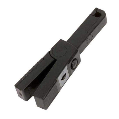
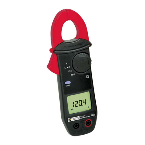
AEMC F03 User manual

F03
ENGLISH User Manual
CLAMP-ON MULTIMETER

Statement of Compliance
Chauvin Arnoux®, Inc. d.b.a. AEMC®Instruments
certifies that this instrument has been calibrated
using standards and instruments traceable to
international standards.
We guarantee that at the time of shipping your
instrument has met its published specifications.
An NIST traceable certificate may be
requested at the time of purchase, or obtained
by returning the instrument to our repair and
calibration facility, for a nominal charge.
The recommended calibration interval for this
instrument is 12 months and begins on the date of
receipt by the customer. For recalibration, please
use our calibration services. Refer to our repair
and calibration section at www.aemc.com.
Serial #: ________________________________
Catalog #: 2129.52
Model #: F03
Please fill in the appropriate date as indicated:
Date Received: _________________________________
Date Calibration Due: _______________________
Chauvin Arnoux®, Inc.
d.b.a AEMC®Instruments
www.aemc.com

Table of Contents
1. INTRODUCTION............................................................................... 3
1.1 International Electrical Symbols................................................3
1.2 DenitionofMeasurementCategories .....................................4
1.3 ReceivingYourShipment..........................................................4
1.4 OrderingInformation.................................................................4
1.4.1 AccessoriesandReplacementParts............................4
2. PRODUCT FEATURES ...................................................................... 5
2.1 Description................................................................................5
2.3 RotarySwitchFunctions ...........................................................7
2.4 CommandButtons ....................................................................7
2.5 HoldButtonPrimaryFunctions .................................................7
2.5.1 DisplayLock ................................................................7
2.5.2 PreselectingMin/MaxMode ........................................7
2.5.3 AutomaticCompensationforLeadResistance............8
2.5.4
AutomaticCompensationofCurrent
MeasurementZero .....................................................8
2.6 HoldButtonSecondaryFunctions(WithRotarySwitch) ..........8
2.6.1 DisableAuto-OffFunction.............................................8
2.6.2 ActivatetheV-LiveFunction ........................................8
2.6.3 DisplayingtheInternalSoftwareVersion .....................9
2.7 YellowButtonPrimaryFunctions ..............................................9
2.7.1 ManualSelectionOfAC/DCMode ..............................9
2.7.2 PossibleSelectionsInContinuityFunction..................9
2.7.3 Setting(°C/°F)whenMeasuringTemperature ............9
2.8 YellowButtonSecondaryFunctions(WithRotarySwitch) .......9
2.8.1 ModicationofAudioIndicationThresholdin
ContinuityTest .............................................................9
2.8.2 Selecting°Cor°FastheDefaultSetting....................10
2.8.3 DefaultConguration ..................................................10
2.9 Min/MaxButtonFunctions ...................................................... 11
2.10 Button.............................................................................11

2.11 LiquidCrystalDisplay .............................................................11
2.11.1 DigitalDisplay .............................................................11
2.11.2 SymbolDisplay ...........................................................12
2.12Buzzer.....................................................................................13
3. SPECIFICATIONS........................................................................... 14
3.1 ReferenceConditions .............................................................14
3.2 ElectricalSpecications ..............................................14
3.2.1 Voltage( ) ..............................................................14
3.2.2 Continuity().......................................... 15
3.2.3 Resistance (Ω)............................................................15
3.2.4 Semi-ConductorTest( ) ..........................................15
3.2.5 Current( ) ..............................................................16
3.2.6 Temperature(T°).........................................................16
3.2.7 PowerSupply..............................................................17
3.3 MechanicalSpecications ......................................................17
3.4 SafetySpecications ..............................................................18
3.5 VariationsinOperatingRange................................................19
4. OPERATION .................................................................................. 21
4.1 VoltageMeasurement-().................................................21
4.2 AudioContinuityTest- ( )...................................................21
4.2.1LeadResistanceCompensation(Ωzero)...............................22
4.3 ResistanceMeasurement-(Ω)...............................................22
4.4 Semi-ConductorTest- ( )....................................................22
4.5 CurrentMeasurements-()...............................................23
4.5.1 CorrectionoftheCurrentMeasurementZero
(DCZero)....................................................................23
4.6 TemperatureMeasurement-(T°) ...........................................23
4.6.1 WithoutaSensor ........................................................23
4.6.2 WithaSensor .............................................................23
MAINTENANCE ................................................................................... 24
5.1 ChangingtheBattery ..............................................................24
5.2 Cleaning..................................................................................24
5.3 Storage ...................................................................................24

Clamp-onMultimeterModelF03
3
CHAPTER 1
INTRODUCTION
Warning
• Never use on circuits with a voltage higher than 600V and an
overvoltagecategoryhigherthanCat.III.
• UseininsideenvironmentswithPollutionDegree2;Temperature
0°Cto+50°C;70%RH.
• Only use accessories compliant with safety standards
(NFEN61010-2-031)600VminandovervoltageCat.III.
• Neveropentheclampbeforedisconnectingallpowersources.
• Neverconnecttothecircuittobemeasurediftheclamp is not
properlyclosed.
• Before any measurement, check the proper positioning of the
cablesandswitch.
• Whenmeasuringcurrent,checkforproperalignmentofthecon-
ductorinrelationtothemarkersandproperclosingofthejaws.
• Always disconnect the clamp from any power source before
changingthebattery.
• Donotperformresistancetests,continuitytestsorsemi-conduc-
tortestsonacircuitunderpower.
1.1 International Electrical Symbols
This symbol signifies that the instrument is protected by double or reinforced
insulation.
This symbol on the instrument indicates a WARNING and that the operator must refer
to the user manual for instructions before operating the instrument. In this manual,
the symbol preceding instructions indicates that if the instructions are not followed,
bodily injury, installation/sample and product damage may result.
Risk of electric shock. The voltage at the parts marked with this symbol may be
dangerous.
This symbol refers to a type A current sensor. This symbol signifies that application
around and removal from HAZARDOUS LIVE conductors is permitted.
In conformity with WEEE 2002/96/EC

4
Clamp-onMultimeterModelF03
1.2 Definition of Measurement Categories
Cat. I: Formeasurements oncircuitsnot directlyconnectedto theAC
supply wall outlet such as protected secondaries, signal level,
andlimitedenergycircuits.
Cat. II: For measurements performed on circuits directly connected to
the electrical distribution system. Examples are measurements
onhouseholdappliancesorportabletools.
Cat. III: For measurements performed in the building installation at
the distribution level such as on hardwired equipment in xed
installationandcircuitbreakers.
Cat. IV: For measurements performed at the primary electrical supply
(<1000V) such as on primary overcurrent protection devices,
ripplecontrolunits,ormeters.
1.3 Receiving Your Shipment
Uponreceivingyour shipment, make surethatthecontents are consis-
tentwiththe packing list. Notifyyourdistributorof any missing items.If
theequipmentappearstobedamaged,leaclaimimmediatelywiththe
carrierandnotifyyourdistributoratonce,givingadetaileddescriptionof
anydamage.Savethedamagedpackingcontainertosubstantiateyour
claim.
1.4 Ordering Information
Clamp-on Multimeter Model F03 ......................................Cat. #2129.52
Includes multimeter, set of red and black leads with probe tips, 1 K-type thermocouple
adapter, 9V battery, carrying pouch and user manual.
1.4.1 Accessories and Replacement Parts
Replacementsetofleads,redandblackwithprobetips .... Cat. #2118.92
GeneralCanvasPouch(4.25x8.5x2”) ............................. Cat. #2119.75
Always use accessories adapted to the voltage and overvoltage cat-
egory of the circuit to be measured (per NF EN 61010).

Clamp-onMultimeterModelF03
5
CHAPTER 2
PRODUCT FEATURES
2.1 Description
TheClamp-onMultimeterModelF03emphasizesreliabilityandsimplicity
ofusetorespondtotheneedsofpowerprofessionals.
Features:
TRMSmeasurement
Acompactunit,integratingthecurrentsensorfor
intensitymeasurementswithoutbreakingthetest
circuit
Outstandingergonomicfeatures:
●
automaticselectionofthetypeofsignaltobe
measured,ACorDC
●
automaticselectionofACorDCmeasurement
●
automaticselectionofmeasurementranges
●
programmableaudiovoltageindication(V-Live)
●
“over-range”indication
●
backlightingofthedigitaldisplay
●
powerauto-off
●
MIN-MAX-PEAKvaluerecordingfunction
●
correctionofdifferencesinDCmeasurement
(DCzero)
●
automaticcompensationofmeasurementlead
resistance (Ωzero)
CompliancewithIECelectricalsafetystandardsand
CEmarkings
Lightandruggedconstructionforelduse

6
Clamp-onMultimeterModelF03
2.2 Model F03 Callouts
1
2
3
4
Jaws CommandButtons
5-wayRotarySwitch LiquidCrystalDisplay

Clamp-onMultimeterModelF03
7
2.3 Rotary Switch Functions
OFF Deactivationoftheclamp,activationisensuredby
selectionofotherfunctions
MeasurementofDCandACvoltages(rmsvalue)
Continuitymeasurement.Testresistanceandsemi-conductor
bypressingtheyellowbutton.
MeasurementofDCandACamperes(rmsvalue)
T° Measurementoftheinternalorexternaltemperature,accord-
ingtothepresenceorabsenceofasensor,in°Cor°F
2.4 Command Buttons
Thebuttonsarecapableof3typesofaction:
Short pressure: <1.3s,validifthebuttonpressureisdetected.
Long pressure: >1.3s,givesaccesstoameasurementoroperating
mode.Holdingorreleasingthebuttonhasnoeffect.
Held pressure: Givesaccesstoameasurementoroperatingmode
andremainsinthismodeaslongaspressureisheld.Releasingthe
buttonreturnsyoutothepreviousmode.
2.5 Hold Button Primary Functions
2.5.1 DISPLAY LOCK
Short-press the HOLD button to freeze/lock the display. Press
againtounlock.
2.5.2 PRESELECTING MIN/MAX MODE
Short-presstheHOLDbutton,thentheMIN/MAXbuttontoprese-
lecttheMIN/MAXmode.PresstheHOLDbuttonagaintomake
theMIN/MAXmodeeffective.
(e.g., use this function to preselect the MIN/MAX mode to prevent
unwanted or mistaken integration of MIN/MAX values.)

8
Clamp-onMultimeterModelF03
2.5.3 AUTOMATIC COMPENSATION FOR LEAD RESISTANCE
PresstheHOLDbuttonwhenthecontinuitytest( )ormeasure-
mentresistancefunction(Ω)isselected.
When the button is released and the display shows zero, the
correction value is put into memory.
If the value measured is higher than 2Ω, this correction is
stoppedandthevalueinmemoryisresettozero.
NOTE: ThiscorrectionisprohibitedinMIN/MAXmode.
2.5.4
AUTOMATIC COMPENSATION OF CURRENT
MEASUREMENT ZERO
PresstheHOLDbuttonwhenthecurrentmeasurementfunction
()isselected.
When the button is released and the display shows zero, the cor-
rection value is put into memory.
If the value measured is higher than 6A, this correction is
stoppedandthevalueinmemoryisresettozero.
2.6 Hold Button Secondary Functions (with rotary switch)
2.6.1 DISABLE AUTO-OFF FUNCTION
WhilepressingdowntheHOLDbutton,turntherotaryswitchfrom
theOFFpositiontothe position.
The unit emits a double beep, then the symbol ashes.
Theselectedcongurationisputintomemorywhenthebuttonis
released(the symbolremainslitcontinuously).
AutomaticstopisreactivatedwhenswitchreturnstoOFF position.
2.6.2 ACTIVATE THE V-LIVE FUNCTION
While pressing down the HOLD button, bring the rotary switch
fromtheOFF positiontothe position.
The unit emits a double beep, then the Vand symbol ashes.
The selected conguration is put into memory when the button
is released (the V symbol becomes xed and the symbol
ashes).
ProceedinthesamewaytodeactivatetheV-Livefunction(the
symboldisappearswhenthebuttonisreleased).

Clamp-onMultimeterModelF03
9
2.6.3 DISPLAYING THE INTERNAL SOFTWARE VERSION
While pressing down the HOLD button, bring the rotary switch
fromtheOFFpositiontotheAposition.
The unit beeps, the software version is displayed in the form
UX.XX for 2 seconds, then all the segments of the display are
shown.
2.7
Yellow Button Primary Functions
2.7.1 MANUAL SELECTION OF AC/DC MODE
Bydefault,theclampswitchestoACorDCmodeautomatically
(AC/DCsymbolashes)fortheAandVfunctions.Whenthemode
ismanuallyselected,theAC/DCsymbolisxed.
Useaseriesofshortpressesontheyellow buttontomanually
selectAC/DCmeasurement,andtoreturntoautomaticmode.
NOTE:
Manual selection is not possible in MIN/MAX or HOLD
mode.
2.7.2 POSSIBLE SELECTIONS IN CONTINUITY FUNCTION
Bydefault,theclampisinthecontinuityfunction( ).
Toselectresistancemeasurement(Ω),semi-conductortestfunc-
tion ( ),andtoreturntothecontinuityfunction( ),perform a
series of short presses on the yellow button.
2.7.3 SETTING (°C / °F) WHEN MEASURING TEMPERATURE
Short-pressthe yellow buttontoselect°Cor°F.The selection
madewillnotbesavedwhentheclampisturnedoff.
2.8
Yellow Button Secondary Functions (with rotary switch)
2.8.1 MODIFICATION OF AUDIO INDICATION THRESHOLD IN
CONTINUITY TEST
Whilepressingdowntheyellow button,bringtherotaryswitch
fromtheOFFpositiontothe position.
The unit beeps, the Ωand symbols appear, along with the
threshold value (40.0 by default).

10
Clamp-onMultimeterModelF03
Adjustmentisthenpossiblefrom1Ωto 40Ωbypressingtheyellow
button(shortpressure:progressionof1Ωby 1Ω;pressandhold:
progressionof10Ωby 10Ω).
Once the value is chosen, activate the rotary switch to memo-
rize.
2.8.2 SELECTING °C OR °F AS THE DEFAULT SETTING
To set either °C or °F as the default,presstheyellow button
downandturntherotaryswitchtotheT°position.
The instrument beeps twice, then the T° symbol lights up and the
°F symbol ashes if the instrument was previously in °C or the °C
symbol ashes if the was in °F.
Theconguationchosenissavedwhenthekeyisreleased.
2.8.3 DEFAULT CONFIGURATION
While pressing down the yellow button, turn the rotary switch
fromtheOFFpositionto position.
The unit emits a double beep, then all the segments of the digital
display and the symbol ashes.
Thedefaultcongurationissetwhenthebuttonisreleased(the
displaynolongerashesandthe symboldisappears).
The default conguration is:
• Audioidenticationthreshold:40Ω
• Auto-off:ON
• V-Livefunction:none
• Unitfortemperaturemeasurement:notcontrolled

Clamp-onMultimeterModelF03
11
2.9 MIN/MAX Button Functions
MIN/MAXoperatesbyend-aroundshiftonshortpressure:
MIN/MAX V and A Functions Other functions
1stpress PEAKvalue MAXvalue
2ndpress MAXvalue MINvalue
3rdpress MINvalue ReturntoMAXvalue
4thpress ReturntoPEAKvalue –
AlongpressonthebuttonwillquittheMIN/MAXmode.
NOTE:InMIN/MAXmode,theAuto-offfunctionoftheunitisunavail-
able ( symbollit).
2.10 Button
Short pressure:Displaybacklightcommand.
Auto-offafter2minutes.
Held pressure:Displayofestimatedremainingbatterypower,inhours.
2.11 Liquid Crystal Display
The liquid crystal display includes the digital display of the measured
values,therelatedunitsandsymbols.
2.11.1 DIGITAL DISPLAY
4digits,9999counts,3decimalpoints,+and-signs(DCandpeakmea-
surement)
+ OL : Positivevaluerangeexceedance(>3999cts)
- OL : Negativevaluerangeexceedance
OL : Unsignedvaluerangeexceedance
- - - - : Indeterminatevalue(middlesegments)

12
Clamp-onMultimeterModelF03
2.11.2 SYMBOL DISPLAY
Flashing:powerlimitedtoapproximately1hour
Steady:batterydrained,operationandaccuracyareno
longerguaranteed
Constantoperation(noautomaticshutdown)
Fixed:Continuitymeasurement
Flashing:V-Livefunctionselected
HOLDFunctionactive
PEAK ONinVandAinMIN/MAXmodeifthemeasurementof
thepeakvalueisselected
MAX IndicatesthedisplayofamaximumvalueinMIN/MAXmode
MIN IndicatesthedisplayofaminimumvalueinMIN/MAXmode
AC Fixed:measurementinACmanualmode
Flashing:measurementinACautomaticmode
DC Fixed:measurementinDCmanualmode
Flashing:measurementinDCautomaticmode
T° Temperaturemeasurement
INT Measurementoftemperaturewhentheterminalsarenot
connected,orthethermocoupleconnectedisfaulty.
EXT Measurementoftemperaturewhenthethermocoupleis
connected
Semi-conductortestonpositionΩ

Clamp-onMultimeterModelF03
13
2.12 Buzzer
Differenttonesareemittedaccordingtothefunctiongiventothebuzzer:
• Short and medium sound:validbutton
• Short and high-pitched sound:prohibitedbutton
• Short and low-pitched sound:exitMIN/MAXmode
• 2 short, high-pitched sounds:validationofaconguration
parameter
• Short and medium sound every 400 ms:voltagemeasuredis
higherthantheunit’sguaranteedsafetyvoltage
• 5 short and medium recurring sounds:automaticshutdownof
theinstrument
• Continuous medium sound: measured continuity value lower
thanprogrammedthreshold,short-circuitconnectionduringsemi-
conductortest
• Modulated medium continuous sound: value measured in
volts,higherthan45VpeakwhentheV-Livefunctionisselected

14
Clamp-onMultimeterModelF03
CHAPTER 3
SPECIFICATIONS
3.1 Reference Conditions
23°C±3°K;RHof45to75%;batterypowerat8.5V±5V;frequencyrange
ofappliedACsignal45to65Hz;positionofconductorcenteredinclamp
jaws;conductordiameter.20";noelectricaleld;noexternalACmagnetic
eld.
3.2 ElectricalSpecications
3.2.1 Voltage ( )
Range 40V 400V 600V*
MeasuringRange** 0.2Vto39.99V 40.0Vto399.9V 400to600V
400to900Vpeak
Accuracy 1%ofReading
+5cts
1%ofReading
+2cts
1%ofReading
+2cts
Resolution 10mV 0.1V 1V
InputImpedance 1MΩ
Overload Protection 600VAC/DC
*In DC, the display indicates +OL above +600V and -OL above -600V (900V in PEAK mode).
In AC, the display indicates OL over 600Vrms (900V in PEAK mode).
**In AC if the value of the voltage measured is <0.15V the display indicates 0.00.
MIN/MAX Mode:
Accuracy:sameasprevioustable+0.2%ofReading
CaptureTime:100mstypical
PEAK Mode:
Accuracy:sameasprevioustable+2%ofReading
CaptureTime:500µstypical(2.5msmax)
Detection Threshold Accuracy (V-Live Mode):
45Vpeak±2V

Clamp-onMultimeterModelF03
15
3.2.2 Continuity ( )
Range 400Ω
MeasuringRange 0.0 to 399.9Ω
Accuracy* 1%ofReading+2cts
Resolution 0.1Ω
OpenCircuitVoltage ≤3.2V
MeasuringCurrent 320µA
Overload Protection 500VACor750VDCorpeak
*with compensation for measurement lead resistance
MIN/MAX Mode:
Accuracy:sameasprevioustable+0.2%ofReading
CaptureTime:100mstypical
3.2.3 Resistance (Ω)
Range 400Ω4000Ω
MeasuringRange 0.0 to 399.9Ω400 to 3999Ω
Accuracy* 1%ofReading+2cts
Resolution 0.1Ω1Ω
OpenCircuitVoltage ≤3.2V
MeasuringCurrent 320µA 40µA
Overload Protection 500VACor750VDCorpeak
*With compensation for measurement cable resistance
MIN/MAX Mode:
Accuracy:sameasprevioustable+0.2%ofReading
CaptureTime:100mstypical
3.2.4 Semi-Conductor Test ( )
Display Range 4V
MeasuringRange 0to3.199V
Accuracy 1%ofReading+2cts
Resolution 1mV
MeasuringCurrent* 2mA to 4mA
Overload Protection 500VACor750VDCorpeak
*Per the voltage measured

16
Clamp-onMultimeterModelF03
MIN/MAX Mode:
Accuracy:sameasprevioustable+0.2%ofReading
CaptureTime:100mstypical
3.2.5 Current ( )
Display Range 40A 400A 600A*
MeasuringRange** 0.20 to 39.99A 40.0 to 399.9A 400to600Apeak
Accuracy*** 1.5%ofReading+10cts 1.5%ofReading+2cts
Resolution 10mA 100mA 1A
*In DC, the display indicates +OL above +400A and -OL above -400A (600A in PEAK mode).
In AC, the display indicates OL over 400Arms (900V in PEAK mode).
**In AC, if the value of the current measured is <0.15A, the display shows 0.00.
***With correction of zero in DC
MIN/MAX Mode:
Accuracy:sameasprevioustable+0.2%ofReading
CaptureTime:100mstypical
PEAK Mode:
Accuracy:sameasprevioustable+0.2%ofReading+0.5A
CaptureTime:500µstypical(2.5msmax)
3.2.6 Temperature (T°)
Function Internal Temperature External Temperature
Typeofsensor Intergratedcircuit Kcouple
Displayrange 400°C
400°F
400°C
400°F
4000°C
4000°F
Measuringrange -10.0°Cto
+50.0°C
-50.0°Cto
+399.9°F
+400°Cto
+1000°C
+15.0°Fto
+120.0°F
-50.0°Fto
+399.9°F
+400°Fto
+1832°F
Accuracy ±1.5°C
±2.7°F
1%ofR±1.5°C
1%ofR±2.7°F
1%ofR±1.5°C
1%ofR±2.7°F
Resolution 0.1°C
0.2°F
1°C
1°F
Detectionofsensorcutoff –INTsymbollitinsteadofEXT
Thermaltimeconstant 0.7min/°C Accordingtothesensormodel
Note: The accuracy stated for external temperature measurement does
not include the accuracy of the K couple.

Clamp-onMultimeterModelF03
17
MIN/MAX Mode:
Accuracy:sameasprevioustable+0.2%ofReading
CaptureTime:100mstypical(every800ms)
3.2.7 Power Supply
Battery: Standard9Valkaline(typeIEC6LF22,6LR61orNEDA1604)
Charge life: 75hor25,000x10smeasurements
Low Battery indicator:
Flashing:Chargelife<1h
Fixed:Changebattery
Auto-off:10minuteswithnoactionontherotaryswitchorthebuttons
3.3 Mechanical Specifications
Temperature:
0
10
20
30
40
50
60
70
80
90
-50 -40-30 -101080706050403020-20 90
➂➂
➁
➀
0
Temperature in °C
Relative humidity in % RH
Operating Temperature:32to122°F(0to50°C);90%RH
Storage Temperature:-40to158°F(-40to70°C);90%RH
Altitude:
Operation:≤2000m
Storage:≤12,000m
Dimensions:2.76x7.6x1.46"(70x193x37mm)
Weight: 9.17oz(260g)
Clamp Tightening Capacity: ≤1.00”(≤26mm)
1.ReferenceRange
2.OperatingRange
3.StorageRange(withoutbattery)

18
Clamp-onMultimeterModelF03
3.4 Safety Specifications
Electrical Safety
(as per EN 61010-1 ed. 95 and 61010-2-032, ed. 93)
• DualInsulation
• CategoryIII
• PollutionDegree2
• RatedVoltage600V(RMSorDC)
Electric Shocks
(test as per IEC 1000-4-5)
• 6kVinRCDmodeonthevoltmeterfunction,aptitudecriterionB
• 2kVinducedonthecurrentmeasurementcable,aptitudecriterion
B
Electromagnetic Compatibility
(as per EN 61326-1 ed. 97 + A1)
Emission:classB
Immunity:
• Electrostaticdischarges:
4kVoncontact,aptitudecriterionB
8kVintheair,aptitudecriterionB
• Radiatedeld:10V/m,aptitudecriterionB
• FastTransients:1kV,aptitudecriterionB
• Conduitinterference:3V/m,aptitudecriterionA
Mechanical Resistance
• Freefall1m (test as per IEC 68-2-32)
• Impacts:0.5J(test as per IEC 68-2-27)
• Vibrations:0.75mm (test as per IEC 68-2-6)
Auto Power OFF (per UL94)
• HousingV0;JawsV0;DisplaywindowV2
Table of contents
Other AEMC Multimeter manuals