5. DESCRIPTION
OF COMPONENTS
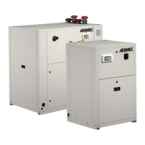
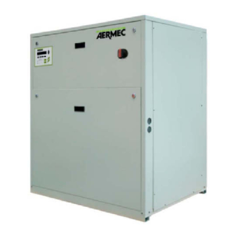
5.1. STRUCTURE
BASEAND SUPPORT STRUCTURE
Made up from hot galvanised sheet steel
elements with suitable thickness. All parts
painted with polyester powder paints (RAL
9002), resistant to atmospheric agents.
Realised in a way to allow total accessibility
to the components internal components. All
panels are covered with sound-absorbent
material with suitable thickness.
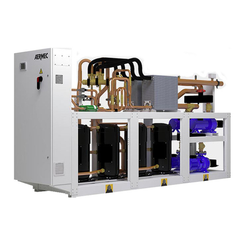
5.2. COOLING CIRCUIT
COMPRESSOR
High efficiency scroll hermetic compressors
(mounted on anti-vibration supports),
activated by a 2-pole electric motor with
internal heat protection.
DISCHARGE CHECK VALVE
CONDENSER EXCHANGE
Plate type (AISI 316). It is insulated externally
with closed cell material to reduce thermal
dispersions.
EVAPORATOR EXCHANGE
Plate type (AISI 316). It is insulated externally
with closed cell material to reduce thermal
dispersions.
Unit with (AISI 316) heat plate, insulated
externally with closed cell material to reduce
heat loss.
Hot gas By-pass valve injection, hot gas device
injection upstream of the evaporator.
DEHYDRATOR FILTER
Mechanical dehydrator filter realised in
ceramics and hygroscopic material, able to
withhold impurities and any traces of humidity
present in the cooling circuit.
LIQUID SIGHT GLASS
MECHANICAL THERMOSTATIC VALVE
The mechanical valve, with external equaliser
positioned at the evaporator inlet, modulates
the flow of gas to the evaporator, according
to the heat load, in order to ensure a correct
heating level of the intake gas.
The valve modulates the flow of gas to the
evaporator, according to the heat load, in order
to ensure a correct heating level of the intake
gas.
5.3. HYDRAULIC CIRCUIT
WRL STANDARD VERSION
(SUPPLIED AS STANDARD)
WATER FILTER
Equipped with steel filtering mesh; prevents
the heat exchangers from clogging.
FLOW SWITCH
It checks that here is water circulation.
Adversary, it blocks the unit.
bar/87PSI
Equipped with a piped discharger and
intervenes by discharges the over pressure in
case of anomalous pressures.
DRAIN VALVE
WRL PUMP/PUMPS VERSION
(SUPPLIED AS STANDARD)
WATER FILTER
Equipped with steel filtering mesh; prevents
the heat exchangers from clogging.
FLOW SWITCH
It checks that here is water circulation.
Adversary, it blocks the unit.
bar/87PSI
Equipped with a piped discharger and
intervenes by discharges the over pressure in
case of anomalous pressures.
EXPANSION VASSEL
With nitrogen pre-load membrane.
DRAIN VALVE
5.4. SAFETY AND CONTROL
LOW PRESSURE TRANSDUCERS
Placed on the low pressure side of the cooling
circuit, it signals the work pressure to the
control board, generating a pre-warning in case
of anomalous pressures.
HIGH PRESSURE TRANSDUCER
Placed on high pressure side of cooling circuit,
signals the work pressure to control board,
generating a pre-warning in case abnormal
pressure occurs.
HIGH PRESSURE PRESSURE SWITCH
With fixed calibration, placed on high pressure
side of cooling circuit, inhibits functioning of
compressor if abnormal work pressure occurs.
5.5. ELECTRIC CONTROL BOARD
AND REGULATION
Electric power and control board,
manufactured in compliance with the EN
60204-1/IEC 204-1 Standards, complete with:
• door lock main isolating switch,
• magnet circuit breaker switches and
contactors for compressors,
• phase sequence control,
• connection clamps to the remote
keyboard (OPTIONAL),
• clamps for signalling the remote alarm,
• clamps for signalling compressor switch-
on status,
• clamps for boiler/resistance alarm signal,
• clamps for differential pressure switch
alarm signal,
• clamps for external air temperature
probe (ACCESSORY),
• electronic control µPC,
• soft-start (OPTIONAL),
• control circuit numbered cables,
• clamps for 3-way valve,
• 0-10V clamps for modulating valve
control.
Electronic controller µPC
The device is the new controller for
management of the water-cooled reversible
units; the new PGD1 8-digit display is clearly
legible, while the icons provide immediate
visibility of machine operation.
Some accesses are protected by password
and only available to the after-sales technical
service.
The electronics also integrates a series of
protection algorithms with the purpose
of preventing any damage to the main
components of the system.
FUNCTIONALITY LIST:
1. Parameterisation of the compressor
switch-on/off times prevent switch on/off
activation at short intervals.
2. In order to prevent breakage of the
plate heat exchanger due to freezing
water, 3 antifreezes, “geothermic, system
and zones” are envisioned which are
contained within. The microprocessor
also envisions compressor block,
whenever the temperature detected by
the heat exchanger output probe is lower
than the anti-freeze set.
3. Water flow rate alarm activated by the
differential pressure switches installed
in series.
4. Condensation control is managed via
speed modulation of the pumps with
phase cut systems or inverters, a 2-way
modulating valve and ON/OFF pumps.
5. Production of DHW through a 3-way
diverter valve or the total recovery
version.
7
IWRLPY. 1403. 5890710_01
