3
INSTALLATION
INSTALLATION SECTION
The complete cooker is floor-mounted and the space in which the appliance is to be fitted must have the following minimum
dimensions:-
A 3mm gap is required each side between the cooker top plate and adjoining work surfaces that maybe fitted, this is to
allow for the safe removal of the top plate, should this be required at a later date.
Where cookers are fitted against side walls which protrude beyond the front of the AGA, a 116mm clearance is required
at the RH side for oven doors access.
If the AGA is to be installed in a brick recess, then the minimum clearance should be increased by at least 10mm on either
side, to allow for the walls not being square and also for the natural dimensional variations found in the castings.
In addition, a minimum clearance of 1000mm must be available at the front of the cooker, to enable the cooker to be
serviced.
Cooker Base or Hearth
It is essential that the base or hearth on which the cooker stands should be level and be capable of supporting the toal
weight of the cooker.
Model EC - 406 kg
Model EE - 584 kg
The top of the hearth must be of non-combustible material thickness of 12mm.
The wall behind the cooker must be of non-combustible material for a minimum thickness of 25mm.
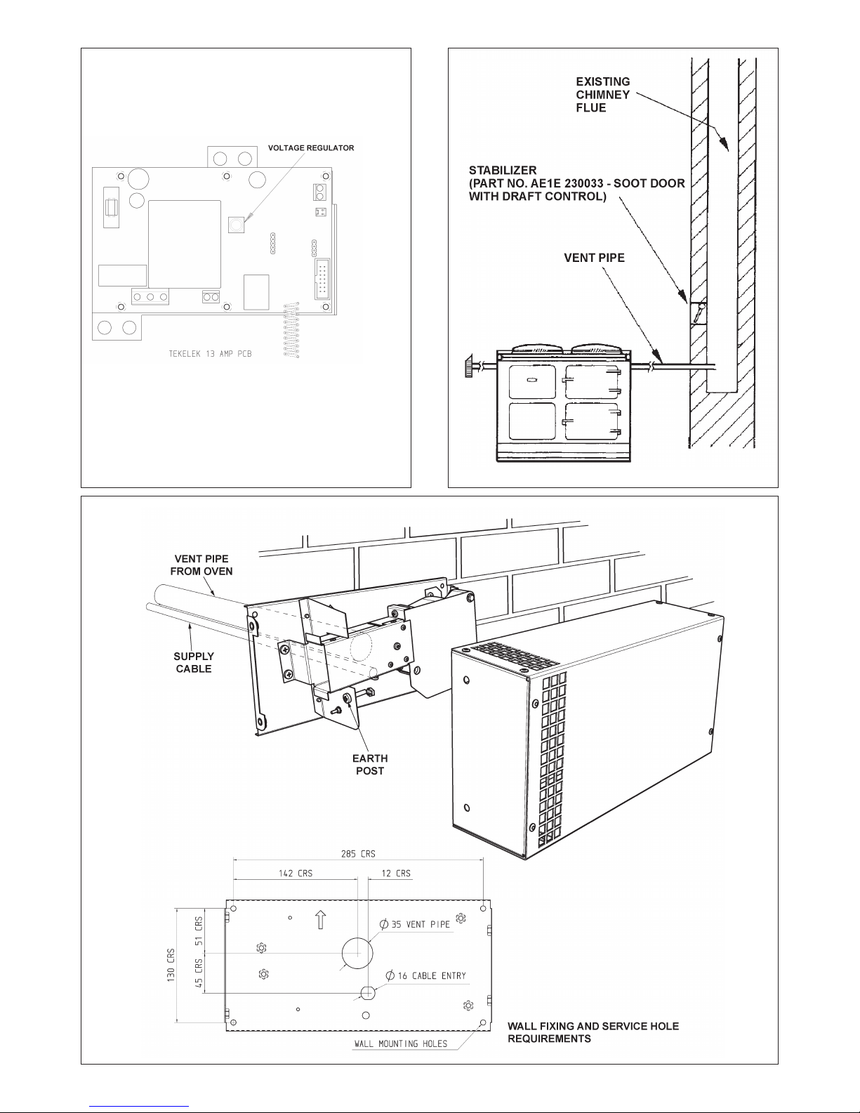
If the oven vent pipe passes through combustible material, there must be an airgap of at least 25mm around the pipe
preferably wrapped with insulation material.
The appliance oven venting pipe can be achieved up to a maximum length of 6 metres, through an outside wall or unused
flue etc. Great care must be taken in all-timber houses.
Tiling
When the cooker is to stand in a recess, or against a wall which is to be tiled, in no circumstances should the tiles overlap
the cooker top plate.
Consumer Protection
As responsible manufacturers we take care to make sure that our products are designed and constructed to meet the
required safety standards when properly installed and used.
IMPORTANT NOTICE: PLEASE READ THE ACCOMPANYING WARRANTY
Any alteration that is not approved by AGA could invalidate the approval of the appliance, operation of the warranty and
could also affect your statutory rights.
In the interests of safety and effective use, please read the following before using your new AGA appliance.
Important
This appliance may contain some of the materials that are indicated. It is the Users/Installers responsibility to ensure that
the necessary personal protective clothing is worn when handling, where applicable, the pertinent parts that contain any
of the listed materials that could be interpreted as being injurious to health and safety, see below for information.
Fire Cement - when handling use disposable gloves.
Glues and Sealants - exercise caution - if these are still in liquid form use face mask and disposable gloves.
Glass Yarn, Mineral Wool, Insulation Pads - may be harmful if inhaled, may be irritating to skin, eyes, nose and throat.
When handling avoid inhaling with skin or eyes. Use disposable gloves, face-masks and eye protection. After handling
wash hands and other exposed parts. When disposing of the product, reduce dust with water spray, ensure that parts are
securely wrapped.