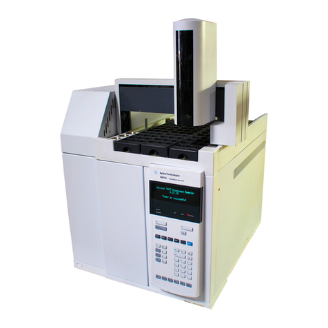
Agilent Technologies 7697A Guide

Agilent Technologies
Agilent 7697A
Headspace Sampler
Maintenance

Notices
© Agilent Technologies, Inc. 2012
No part of this manual may be reproduced
in any form or by any means (including
electronic storage and retrieval or
translation into a foreign language) without
prior agreement and written consent from
Agilent Technologies, Inc. as governed by
United States and international copyright
laws.
Manual Part Number
G4556-90017
Edition
Third edition, February 2012
Second edition, November 2011
First edition, February, 2011
Printed in USA
Agilent Technologies, Inc.
2850 Centerville Road
Wilmington, DE 19808-1610 USA
安捷伦科技 (上海)有限公司
上海市浦东新区外高桥保税区
英伦路 412 号
联系电话:(800)820 3278
Warranty
The material contained in this document
is provided “as is,” and is subject to being
changed, without notice, in future
editions. Further, to the maximum extent
permitted by applicable law, Agilent
disclaims all warranties, either express
or implied, with regard to this manual and
any information contained herein,
including but not limited to the implied
warranties of merchantability and fitness
for a particular purpose. Agilent shall not
be liable for errors or for incidental or
consequential damages in connection
with the furnishing, use, or performance
of this document or of any information
contained herein. Should Agilent and the
user have a separate written agreement
with warranty terms covering the
material in this document that conflict
with these terms, the warranty terms in
the separate agreement shall control.
Safety Notices
CAUTION
A CAUTION notice denotes a hazard. It
calls attention to an operating
procedure, practice, or the like that, if
not correctly performed or adhered to,
could result in damage to the product
or loss of important data. Do not
proceed beyond a CAUTION notice
until the indicated conditions are fully
understood and met.
WARNING
A WARNING notice denotes a hazard.
It calls attention to an operating
procedure, practice, or the like that, if
not correctly performed or adhered to,
could result in personal injury or
death. Do not proceed beyond a
WARNING notice until the indicated
conditions are fully understood and
met.

Maintenance 3
Contents
1 About Maintaining the Headspace Sampler
Overview of Maintenance 6
Where to find a procedure 6
Early Maintenance Feedback feature 6
Tools and Materials Required for Maintenance 7
Safety 8
2 Removing Covers and Components
To Remove the Pneumatics Front Cover 10
To Remove the Valve Thermal Enclosure 11
To Install the Valve Thermal Enclosure 12
To Remove the Pneumatics Assembly 13
To Remove the Valve Cover 17
To Remove the Loop Cover 18
To Remove the Valve/Loop Cover 19
To Remove the Tray Assembly (111-Vial Model) 20
To Remove the Rotating Top Cover (12-Vial Model) 22
3 Maintenance
To Clean the Sample Tray (12-Vial Model) 24
To Replace the Sample Tray Seals (12-Vial Model) 26
To Clean the Sample Tray Assembly (111-Vial Model) 27
To Clean the Oven (111-Vial Model) 29
To Replace the Sample Probe 34
To Replace the Sample Loop 37
To Replace the Sample Loop Adapters 42
To Replace the 6 Port Valve 45
To Replace the 6 Port Valve Rotor 46
To Clean the 6 Port Valve and Rotor 49
To Attach the Transfer Line to a Split Splitless or Multimode Inlet 50
To Attach the Transfer Line to a Volatiles Interface 52
To Attach the Transfer Line to a Purged Packed Inlet 55

5
Agilent 7697A Headspace Sampler
Maintenance
Agilent Technologies
1
About Maintaining the Headspace
Sampler
Overview of Maintenance 6
Tools and Materials Required for Maintenance 7
Safety 8
This section provides an overview of the maintenance
procedures included in this document. It also lists the tools
needed for routine maintenance and the safety information
one should be aware of before performing a maintenance
task.

6Maintenance
1About Maintaining the Headspace Sampler
Overview of Maintenance
This manual details the routine tasks needed to maintain the
7697A Headspace Sampler (Headspace). The procedures
assume a basic knowledge of tool use and of Headspace
operation. Readers are, for example, expected to know how
to:
•Safely turn devices on and off
•Prepare and run samples
•Enter and develop methods
•Make typical pneumatic connections using Swagelok and
other standard fittings
Where to find a procedure
Included in this manual are sections on maintaining the
following Headspace components:
•Fused silica column
•Transfer line
•Sample needle
•Sample loop
•6 port valve
•Oven
•Vial racks
Early Maintenance Feedback feature
Both the Headspace and Agilent Instrument Utilities include
the capability to alert users of upcoming maintenance needs.
This feature, called Early Maintenance Feedback, notifies
users when a counter (such as a gripper pad counter, valve
loop counter, or probe cycle counter) has reached the
specified maintenance point. After performing the required
maintenance, reset the applicable counter. Refer to the
Operation manual for details about this feature.

About Maintaining the Headspace Sampler 1
Maintenance 7
Tools and Materials Required for Maintenance
Table 1 lists the tools needed for most Headspace
maintenance procedures. The specific tools required to
perform a maintenance procedure are listed in step 1 of the
procedure.
Table 1 Required Tools
Tool Description
T- 20 Torx Driver
T- 20 Torx Key (for working in limited space)
Long T- 20 Torx Driver
T- 10 Torx Driver
T- 10 Torx Key (for working in limited space)
Small cross head screwdriver
Large cross head screwdriver
Needle nose pliers

8Maintenance
1About Maintaining the Headspace Sampler
Safety
Before performing a maintenance task, read the important
safety and regulatory information found in the 7697A
Headspace Sampler Safety manual.

9
Agilent 7697A Headspace Sampler
Maintenance
Agilent Technologies
2
Removing Covers and Components
To Remove the Pneumatics Front Cover 10
To Remove the Valve Thermal Enclosure 11
To Install the Valve Thermal Enclosure 12
To Remove the Pneumatics Assembly 13
To Remove the Valve Cover 17
To Remove the Loop Cover 18
To Remove the Valve/Loop Cover 19
To Remove the Tray Assembly (111-Vial Model) 20
To Remove the Rotating Top Cover (12-Vial Model) 22
This section describes how to remove covers and components
as needed for routine maintenance.
Only the covers and components listed in this chapter
should be removed. Removing other Headspace covers can
compromise the safety features of the instrument, leading to
personal injury or damage to the instrument.

10 Maintenance
2Removing Covers and Components
To Remove the Pneumatics Front Cover
The pneumatics front cover protects the valve thermal
enclosure and transfer line. To remove the pneumatics front
cover:
1Press [Tray Park/Carousel Advance] to “park” the tray (if
available).
2Remove the T- 20 screw that secures the cover in place
(Figure 1).
Figure 1 Remove the T-20 Torx screw from the pneumatics front cover
3Slide the cover out, then lift to remove.
Reinstallation is the reverse of these steps.
Pneumatics
front cover

Removing Covers and Components 2
Maintenance 11
To Remove the Valve Thermal Enclosure
The valve thermal enclosure protects the 6 port valve and
sample loop. To remove the valve thermal enclosure:
1Remove the pneumatics front cover. See “To Remove the
Pneumatics Front Cover”.
2Cool down the sample loop and sample probe to a safe
handling temperature. If you will disconnect the transfer
line from the Headspace, cool down the transfer line and
GC column oven as needed.
3Carefully lift the valve thermal enclosure straight up and
off of the headspace sampler (Figure 2).
Figure 2 Lift the valve thermal enclosure straight up
WARNING
The valve thermal enclosure and its contents may be hot enough
to cause burns.

12 Maintenance
2Removing Covers and Components
To Install the Valve Thermal Enclosure
To install the valve thermal enclosure:
1Locate the valve thermal enclosure’s transfer line cutout,
and align it with the transfer line (Figure 3).
Figure 3 The valve thermal enclosure’s transfer line cutout
2Carefully lower the valve thermal enclosure over the valve
and loop areas with the transfer line cutout facing the
left side of the Headspace.
Transfer line cutout
CAUTION
Be sure to not damage the transfer line and other nearby cables
when lowering the valve thermal enclosure.

Removing Covers and Components 2
Maintenance 13
To Remove the Pneumatics Assembly
Remove the pneumatics assembly (Figure 4) to access the
oven components.
Figure 4 Pneumatics assembly without covers
To remove the pneumatics assembly:
1Set your GC oven, Headspace oven, and transfer line to
ambient temperatures and wait for them to cool.
2Once the GC oven, Headspace oven, and transfer line have
cooled to ambient temperature, turn the Headspace off
and unplug the power cord.
3Turn all gas flows off at their sources, and if necessary,
disconnect the gas lines at the pneumatics assembly back
panel.
4Remove the pneumatics assembly front cover. See “To
Remove the Pneumatics Front Cover”.
Pneumatics
assembly

14 Maintenance
2Removing Covers and Components
5If necessary, disconnect the transfer line from the
pneumatics assembly or GC.
aRemove the valve thermal enclosure. See “To Remove
the Valve Thermal Enclosure”.
bDepending on your hardware configuration, remove the
valve cover, or the valve/loop cover. See “To Remove
the Valve Cover” or “To Remove the Valve/Loop Cover”.
cLoosen the 3/16- inch nut in the internal reducer
(Figure 5).
Figure 5 3/16-inch internal reducer with valve cover removed and loop
cover shown (the valve/loop cover is similar)
dRemove the fused silica column from the internal
reducer.
eHold the transfer line by the mounting bracket, and
carefully slide the transfer line out of the Headspace
and set it aside.

Removing Covers and Components 2
Maintenance 15
6Completely loosen the two T- 20 Torx captive thumbscrews
that are inset at the front of the pneumatics assembly
(Figure 6).
Figure 6 Locate and loosen the two front thumbscrews
7Completely loosen the T- 20 Torx captive thumbscrew at
the back of the pneumatics assembly (Figure 7).
Figure 7 Overhead view of the back thumbscrew securing the
pneumatics assembly

16 Maintenance
2Removing Covers and Components
8Completely loosen the T- 20 Torx captive thumbscrew at
the middle of the pneumatics assembly near the two
proportional valves (Figure 8).
Figure 8 Overhead view of the middle thumbscrew securing the
pneumatics assembly
9Lift the pneumatics assembly straight up, rotate the
assembly about 90- degrees counterclockwise, and lay it
across the back of the Headspace.
Reinstallation is the reverse of these steps.
CAUTION
Do not remove the pneumatics assembly completely. Be careful to
not damage any attached cables and gas lines when moving the
pneumatics assembly.

Removing Covers and Components 2
Maintenance 17
To Remove the Valve Cover
1Gather the following:
•T- 20 Torx driver
2Remove the pneumatics front cover. See “To Remove the
Pneumatics Front Cover”.
3Remove the valve thermal enclosure. See “To Remove the
Valve Thermal Enclosure”.
4Completely loosen the two T- 20 Torx captive screws on
the valve cover (Figure 9).
Figure 9 Valve cover
5Remove the valve cover.
Reinstallation is the reverse of these steps.
Valve cover

18 Maintenance
2Removing Covers and Components
To Remove the Loop Cover
1Gather the following:
•T- 20 Torx driver
2Remove the pneumatics front cover. See “To Remove the
Pneumatics Front Cover”.
3Remove the valve thermal enclosure. See “To Remove the
Valve Thermal Enclosure”.
4Completely loosen the T- 20 Torx captive screw on the
loop cover (Figure 10).
Figure 10 Loop cover
5Remove the loop cover.
Reinstallation is the reverse of these steps.
Loop cover

Removing Covers and Components 2
Maintenance 19
To Remove the Valve/Loop Cover
1Gather the following:
•T- 20 Torx driver
2Remove the pneumatics front cover. See “To Remove the
Pneumatics Front Cover”.
3Remove the valve thermal enclosure. See “To Remove the
Valve Thermal Enclosure”.
4Completely loosen the three T- 20 Torx captive screws on
the valve/loop cover (Figure 11).
Figure 11 Valve/loop cover
5Remove the valve/loop cover.
Reinstallation is the reverse of these steps.

20 Maintenance
2Removing Covers and Components
To Remove the Tray Assembly (111-Vial Model)
1Gather the following:
•Lint- free gloves
2Set your GC oven, Headspace oven, and transfer line to
ambient temperatures and wait for them to cool.
3Once the GC oven, Headspace oven, and transfer line have
cooled to ambient temperature, turn the Headspace off
and unplug the power cord.
4Turn all gas flows off at their sources.
5Remove all sample vials and vial racks.
6Lift the front of the tray assembly up and disconnect the
two cable connections underneath the tray (Figure 12).
Figure 12 Tray cable connections
Cable in clip
Cable connections
Other manuals for 7697A
4
Table of contents
Other Agilent Technologies Medical Equipment manuals
Agilent Technologies
Agilent Technologies 5200 Installation and operating manual

Agilent Technologies
Agilent Technologies 7697A User manual

Agilent Technologies
Agilent Technologies Heartstream FR2 User manual

Agilent Technologies
Agilent Technologies 7100 Instruction Manual

Agilent Technologies
Agilent Technologies PageWriter 200 User manual

Agilent Technologies
Agilent Technologies 5DX User manual

Agilent Technologies
Agilent Technologies Heartstream FR2 User manual

Agilent Technologies
Agilent Technologies M1205A V26 User manual
Agilent Technologies
Agilent Technologies 7697A Operating instructions

Agilent Technologies
Agilent Technologies M4735A User manual