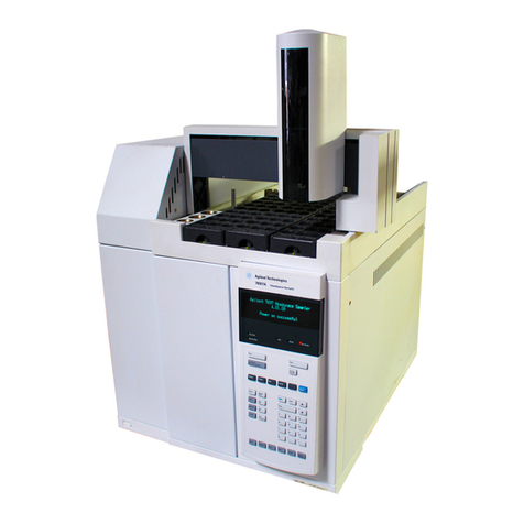
Agilent Technologies M1205A V26 User manual

3DUW1R0/
3ULQWHG-XQH
7KLUG(GLWLRQ
$JLOHQW0$
9DQG9
6HUYLFH*XLGH

1RWLFH
This document contains proprietary information which is protected by copyright. All
Rights Reserved. Reproduction, adaptation, or translation without prior written
permission is prohibited, except as allowed under the copyright laws.
Agilent Technologies
Healthcare Solutions Group Headquarters
3000 Minuteman Road
Andover, MA 01810
1-800-934-7372
Publication number
M1205-9303L
Printed 06/2000
Warranty
The information contained in this document is subject to change without notice.
Agilent makes no warranty of any kind with regard to this material, including, but not
limited to, the implied warranties or merchantability and fitness for a particular
purpose.
Agilent shall not be liable for errors contained herein or for incidental or
consequential damages in connection with the furnishing, performance, or use of this
material.
Copyright © Agilent Technologies, Inc. 1998, 1999, 2000

3ULQWLQJ+LVWRU\
New editions of this document will incorporate all material updated since the
previous edition. Update packages may be issued between editions and contain
replacement and additional pages to be merged by a revision date at the bottom of the
page. Note that pages which are rearranged due to changes on a previous page are not
considered revised.
The documentation printing date and part number indicate its current edition. The
printing date and part number change when a new edition is printed.
First Edition .........................................September 1998
Part Number M1205-9303K
Second Edition.....................................April 1999
Part Number M1205-9303L
Third Edition........................................June 2000


&RQWHQWV
Content 5
2YHUYLHZ 2YHUYLHZ
&KDSWHU,QWURGXFLQJWKH$JLOHQW996HULHV
Objective . . . . . . . . . . . . . . . . . . . . . . . . . . . . . . . . . . . . . . . . . . . . . . . . . . . . . . . . . . . . . . . . . . . . . . . . . . . 1-1
In this chapter . . . . . . . . . . . . . . . . . . . . . . . . . . . . . . . . . . . . . . . . . . . . . . . . . . . . . . . . . . . . . . . . . . . . . . . 1-1
Features. . . . . . . . . . . . . . . . . . . . . . . . . . . . . . . . . . . . . . . . . . . . . . . . . . . . . . . . . . . . . . . . . . . . . . . . . . . . . . . . 1-2
Physical, Functional Overview. . . . . . . . . . . . . . . . . . . . . . . . . . . . . . . . . . . . . . . . . . . . . . . . . . . . . . . . . . . . . . 1-4
Mainframe . . . . . . . . . . . . . . . . . . . . . . . . . . . . . . . . . . . . . . . . . . . . . . . . . . . . . . . . . . . . . . . . . . . . . . . . . . 1-4
Display . . . . . . . . . . . . . . . . . . . . . . . . . . . . . . . . . . . . . . . . . . . . . . . . . . . . . . . . . . . . . . . . . . . . . . . . . . . . 1-4
System Board . . . . . . . . . . . . . . . . . . . . . . . . . . . . . . . . . . . . . . . . . . . . . . . . . . . . . . . . . . . . . . . . . . . . . . . 1-6
Interface Connections . . . . . . . . . . . . . . . . . . . . . . . . . . . . . . . . . . . . . . . . . . . . . . . . . . . . . . . . . . . . . . . . . 1-7
Flat Panel Adapter Board . . . . . . . . . . . . . . . . . . . . . . . . . . . . . . . . . . . . . . . . . . . . . . . . . . . . . . . . . . . . . . 1-8
Power Supply . . . . . . . . . . . . . . . . . . . . . . . . . . . . . . . . . . . . . . . . . . . . . . . . . . . . . . . . . . . . . . . . . . . . . . . 1-8
Plug-in Satellite Rack . . . . . . . . . . . . . . . . . . . . . . . . . . . . . . . . . . . . . . . . . . . . . . . . . . . . . . . . . . . . . . . . 1-10
Parameter Modules . . . . . . . . . . . . . . . . . . . . . . . . . . . . . . . . . . . . . . . . . . . . . . . . . . . . . . . . . . . . . . . . . . 1-11
Front Panel . . . . . . . . . . . . . . . . . . . . . . . . . . . . . . . . . . . . . . . . . . . . . . . . . . . . . . . . . . . . . . . . . . . . . . . . 1-12
Interfaces . . . . . . . . . . . . . . . . . . . . . . . . . . . . . . . . . . . . . . . . . . . . . . . . . . . . . . . . . . . . . . . . . . . . . . . . . . 1-15
Agilent Patient Care System Interface . . . . . . . . . . . . . . . . . . . . . . . . . . . . . . . . . . . . . . . . . . . . . . . . . . . 1-16
RS-232 Network . . . . . . . . . . . . . . . . . . . . . . . . . . . . . . . . . . . . . . . . . . . . . . . . . . . . . . . . . . . . . . . . . . . . 1-16
Patient Data Management . . . . . . . . . . . . . . . . . . . . . . . . . . . . . . . . . . . . . . . . . . . . . . . . . . . . . . . . . . . . . 1-16
Specifications . . . . . . . . . . . . . . . . . . . . . . . . . . . . . . . . . . . . . . . . . . . . . . . . . . . . . . . . . . . . . . . . . . . . . . . . . . 1-17
Functionality and Option Sets . . . . . . . . . . . . . . . . . . . . . . . . . . . . . . . . . . . . . . . . . . . . . . . .. . . . . . . . . 1-17
Dimension and Weight . . . . . . . . . . . . . . . . . . . . . . . . . . . . . . . . . . . . . . . . . . . . . . . . . . . . . . . . . . . . . . . 1-17
Environmental . . . . . . . . . . . . . . . . . . . . . . . . . . . . . . . . . . . . . . . . . . . . . . . . . . . . . . . . . . . . . . . . . . . . . . 1-18
Safety . . . . . . . . . . . . . . . . . . . . . . . . . . . . . . . . . . . . . . . . . . . . . . . . . . . . . . . . . . . . . . . . . . . . . . . . . . . . 1-18
AC Input . . . . . . . . . . . . . . . . . . . . . . . . . . . . . . . . . . . . . . . . . . . . . . . . . . . . . . . . . . . . . . . . . . . . . . . . . . 1-18
Patient Data Management . . . . . . . . . . . . . . . . . . . . . . . . . . . . . . . . . . . . . . . . . . . . . . . . . . . . . . . . . . . . . 1-19
Display . . . . . . . . . . . . . . . . . . . . . . . . . . . . . . . . . . . . . . . . . . . . . . . . . . . . . . . . . . . . . . . . . . . . . . . . . . . 1-20
Parameter Modules . . . . . . . . . . . . . . . . . . . . . . . . . . . . . . . . . . . . . . . . . . . . . . . . . . . . . . . . . . . . . . . . . . 1-20
Plug-in Satellite Racks . . . . . . . . . . . . . . . . . . . . . . . . . . . . . . . . . . . . . . . . . . . . . . . . . . . . . . . . . . . . . . . 1-20
Mounting Options. . . . . . . . . . . . . . . . . . . . . . . . . . . . . . . . . . . . . . . . . . . . . . . . . . . . . . . . . . . . . . . . . . . . . . . 1-20
Practice Exercise. . . . . . . . . . . . . . . . . . . . . . . . . . . . . . . . . . . . . . . . . . . . . . . . . . . . . . . . . . . . . . . . . . . . . . . . 1-21
Practice Exercise Answers . . . . . . . . . . . . . . . . . . . . . . . . . . . . . . . . . . . . . . . . . . . . . . . . . . . . . . . . . . . . 1-23
&KDSWHU7HVWLQJ0DLQWDLQLQJWKH$JLOHQW996HULHV
Objectives . . . . . . . . . . . . . . . . . . . . . . . . . . . . . . . . . . . . . . . . . . . . . . . . . . . . . . . . . . . . . . . . . . . . . . . . . . . . . . 2-1
Concepts . . . . . . . . . . . . . . . . . . . . . . . . . . . . . . . . . . . . . . . . . . . . . . . . . . . . . . . . . . . . . . . . . . . . . . . . . . . . . . . 2-1
Maintenance Checklist . . . . . . . . . . . . . . . . . . . . . . . . . . . . . . . . . . . . . . . . . . . . . . . . . . . . . . . . . . . . . . . . . . . . 2-2
Test and Inspection Requirements . . . . . . . . . . . . . . . . . . . . . . . . . . . . . . . . . . . . . . . . . . . . . . . . . . . . . . . . . . . 2-3
Power On and Performance Tests . . . . . . . . . . . . . . . . . . . . . . . . . . . . . . . . . . . . . . . . . . . . . . . . . . . . . . . . 2-5
Safety Tests . . . . . . . . . . . . . . . . . . . . . . . . . . . . . . . . . . . . . . . . . . . . . . . . . . . . . . . . . . . . . . . . . . . . . . . . 2-11
General Inspections of the System . . . . . . . . . . . . . . . . . . . . . . . . . . . . . . . . . . . . . . . . . . . . . . . . . . . . . . . . . . 2-15
Inspect the System Hardware . . . . . . . . . . . . . . . . . . . . . . . . . . . . . . . . . . . . . . . . . . . . . . . . . . . . . . . . . . 2-15
Inspect the Cables and Cords . . . . . . . . . . . . . . . . . . . . . . . . . . . . . . . . . . . . . . . . . . . . . . . . . . . . . . . . . . 2-15
Inspect the LEDs of the System . . . . . . . . . . . . . . . . . . . . . . . . . . . . . . . . . . . . . . . . . . . . . . . . . . . . . . . . 2-16
Inspect the Flat Panel Display . . . . . . . . . . . . . . . . . . . . . . . . . . . . . . . . . . . . . . . . . . . . . . . . . . . . . . . . . 2-16
Inspect the Controls of the System . . . . . . . . . . . . . . . . . . . . . . . . . . . . . . . . . . . . . . . . . . . . . . . . . . . . . . 2-17
Performance Assurance Test. . . . . . . . . . . . . . . . . . . . . . . . . . . . . . . . . . . . . . . . . . . . . . . . . . . . . . . . . . . . . . . 2-18
Replacement of Backlight Tube Assembly. . . . . . . . . . . . . . . . . . . . . . . . . . . . . . . . . . . . . . . . . . . . . . . . . . . . 2-19

6 Contents
Battery Care and Handling . . . . . . . . . . . . . . . . . . . . . . . . . . . . . . . . . . . . . . . . . . . . . . . . . . . . . . . . . . . . . . . . 2-19
Cleaning and Disinfecting Procedures . . . . . . . . . . . . . . . . . . . . . . . . . . . . . . . . . . . . . . . . . . . . . . . . . . . . . . . 2-23
Objective . . . . . . . . . . . . . . . . . . . . . . . . . . . . . . . . . . . . . . . . . . . . . . . . . . . . . . . . . . . . . . . . . . . . . . . . . . 2-23
Concepts . . . . . . . . . . . . . . . . . . . . . . . . . . . . . . . . . . . . . . . . . . . . . . . . . . . . . . . . . . . . . . . . . . . . . . . . . . 2-23
General Cleaning of the System . . . . . . . . . . . . . . . . . . . . . . . . . . . . . . . . . . . . . . . . . . . . . . . . . . . . . . . . 2-24
General Disinfecting of the System . . . . . . . . . . . . . . . . . . . . . . . . . . . . . . . . . . . . . . . . . . . . . . . . . . . . . 2-25
Cleaning the Recorder Module . . . . . . . . . . . . . . . . . . . . . . . . . . . . . . . . . . . . . . . . . . . . . . . . . . . . . . . . . 2-26
Replacing Recorder Paper . . . . . . . . . . . . . . . . . . . . . . . . . . . . . . . . . . . . . . . . . . . . . . . . . . . . . . . . . . . . 2-27
Removing Paper Loaded Backwards . . . . . . . . . . . . . . . . . . . . . . . . . . . . . . . . . . . . . . . . . . . . . . . . . . . . 2-29
Cleaning the Blood Analysis Module . . . . . . . . . . . . . . . . . . . . . . . . . . . . . . . . . . . . . . . . . . . . . . . . . . . . 2-30
Upgrade and Cloning Instructions . . . . . . . . . . . . . . . . . . . . . . . . . . . . . . . . . . . . . . . . . . . . . . . . . . . . . . . . . . 2-31
Parts Checklist . . . . . . . . . . . . . . . . . . . . . . . . . . . . . . . . . . . . . . . . . . . . . . . . . . . . . . . . . . . . . . . . . . . . . 2-31
Connecting the Flash Programming Tool . . . . . . . . . . . . . . . . . . . . . . . . . . . . . . . . . . . . . . . . . . . . . . . . . 2-34
Upgrading the Utility CPU Software . . . . . . . . . . . . . . . . . . . . . . . . . . . . . . . . . . . . . . . . . . . . . .. . . . . . 2-36
Upgrading the Application CPU Software . . . . . . . . . . . . . . . . . . . . . . . . . . . . . . . . . . . . . . . . . . . . . . . . 2-39
Performing an EEPROM Upgrade . . . . . . . . . . . . . . . . . . . . . . . . . . . . . . . . . . . . . . . . . . . . . . . . . . . . . . 2-41
Performing EEPROM Cloning . . . . . . . . . . . . . . . . . . . . . . . . . . . . . . . . . . . . . . . . . . . . . . . . . . . . . . . . . 2-50
EEPROM Upgrades Between Application Bundles . . . . . . . . . . . . . . . . . . . . . . . . . . . . . . . . . . . . . . . . . 2-52
&KDSWHU7URXEOHVKRRWLQJWKH$JLOHQW996HULHV
Objective . . . . . . . . . . . . . . . . . . . . . . . . . . . . . . . . . . . . . . . . . . . . . . . . . . . . . . . . . . . . . . . . . . . . . . . . . . . 3-1
In this chapter . . . . . . . . . . . . . . . . . . . . . . . . . . . . . . . . . . . . . . . . . . . . . . . . . . . . . . . . . . . . . . . . . . . . . . . 3-1
Isolating and Solving Instrument Problems . . . . . . . . . . . . . . . . . . . . . . . . . . . . . . . . . . . . . . . . . . . . . . . . . . . . 3-2
Troubleshooting Checklists . . . . . . . . . . . . . . . . . . . . . . . . . . . . . . . . . . . . . . . . . . . . . . . . . . . . . . . . . . . . . . . . 3-5
Check for Obvious Problems . . . . . . . . . . . . . . . . . . . . . . . . . . . . . . . . . . . . . . . . . . . . . . . . . . . . . . . . . . . 3-5
Checks before opening the instrument . . . . . . . . . . . . . . . . . . . . . . . . . . . . . . . . . . . . . . . . . . . . . . . . . . . . 3-5
Isolating problems to the correct subassembly . . . . . . . . . . . . . . . . . . . . . . . . . . . . . . . . . . . . . . . . . . . . . . 3-8
Monochrome Flat Panel . . . . . . . . . . . . . . . . . . . . . . . . . . . . . . . . . . . . . . . . . . . . . . . . . . . . . . . . . . . . . . 3-10
Color Flat Panel . . . . . . . . . . . . . . . . . . . . . . . . . . . . . . . . . . . . . . . . . . . . . . . . . . . . . . . . . . . . . . . . . . . . 3-11
Blown Fuses (Model V24CT/V26CT) . . . . . . . . . . . . . . . . . . . . . . . . . . . . . . . . . . . . . . . . . . . . . . . . . . . 3-11
Parameter Rack/Module Fault (Model V24CT/V26CT) . . . . . . . . . . . . . . . . . . . . . . . . . . . . . . . . . . . . . 3-14
Battery Problems . . . . . . . . . . . . . . . . . . . . . . . . . . . . . . . . . . . . . . . . . . . . . . . . . . . . . . . . . . . . . . . . . . . 3-14
&KDSWHU8VLQJ6XSSRUW )XQFWLRQV
Objective . . . . . . . . . . . . . . . . . . . . . . . . . . . . . . . . . . . . . . . . . . . . . . . . . . . . . . . . . . . . . . . . . . . . . . . . . . . 4-1
In this chapter . . . . . . . . . . . . . . . . . . . . . . . . . . . . . . . . . . . . . . . . . . . . . . . . . . . . . . . . . . . . . . . . . . . . . . . 4-1
Using Support Functions . . . . . . . . . . . . . . . . . . . . . . . . . . . . . . . . . . . . . . . . . . . . . . . . . . . . . . . . . . . . . . . . . . 4-2
Error Codes . . . . . . . . . . . . . . . . . . . . . . . . . . . . . . . . . . . . . . . . . . . . . . . . . . . . . . . . . . . . . . . . . . . . . . . . . 4-2
System Configuration Problems . . . . . . . . . . . . . . . . . . . . . . . . . . . . . . . . . . . . . . . . . . . . . . . . . . . . . . . . . 4-8
System Hardware/Software Problem/RAM Problem . . . . . . . . . . . . . . . . . . . . . . . . . . . . . . . . . . . . . . . . . 4-8
General Error Code List . . . . . . . . . . . . . . . . . . . . . . . . . . . . . . . . . . . . . . . . . . . . . . . . . . . . . . . . . . . . . . . 4-9
Error Code List for Specific Device IDs Other Than 16400 (4010H) . . . . . . . . . . . . . . . . . . . . . . . . . . . 4-10
Using the Service Mode . . . . . . . . . . . . . . . . . . . . . . . . . . . . . . . . . . . . . . . . . . . . . . . . . . . . . . . . . . . . . . . . . . 4-11
Accessing Service Mode . . . . . . . . . . . . . . . . . . . . . . . . . . . . . . . . . . . . . . . . . . . . . . . . . . . . . . . . . . . . . . 4-11
Facilities Available in the Service Mode . . . . . . . . . . . . . . . . . . . . . . . . . . . . . . . . . . . . . . . . . . .. . . . . . 4-11
Changing the Global Switches . . . . . . . . . . . . . . . . . . . . . . . . . . . . . . . . . . . . . . . . . . . . . . . . . . . . . . . . . 4-12
Setting the Date and Time . . . . . . . . . . . . . . . . . . . . . . . . . . . . . . . . . . . . . . . . . . . . . . . . . . . . . . . . . . . . 4-13
Displaying the Status Log . . . . . . . . . . . . . . . . . . . . . . . . . . . . . . . . . . . . . . . . . . . . . . . . . . . . . . . . . . . . . 4-13
To Access Monitor Revisions Screen . . . . . . . . . . . . . . . . . . . . . . . . . . . . . . . . . . . . . . . . . . . . . . . . . . . . 4-14
Summary of the Power On Modes . . . . . . . . . . . . . . . . . . . . . . . . . . . . . . . . . . . . . . . . . . . . . . . . . . . . . . 4-15
Network Test . . . . . . . . . . . . . . . . . . . . . . . . . . . . . . . . . . . . . . . . . . . . . . . . . . . . . . . . . . . . . . . . . . . . . . 4-17

Contents 7
Performing the RS232 Loopback Test . . . . . . . . . . . . . . . . . . . . . . . . . . . . . . . . . . . . . . . . . . . . . . . . . . . 4-21
Display Tests . . . . . . . . . . . . . . . . . . . . . . . . . . . . . . . . . . . . . . . . . . . . . . . . . . . . . . . . . . . . . . . . . . . . . . 4-23
Description of the Boot Process . . . . . . . . . . . . . . . . . . . . . . . . . . . . . . . . . . . . . . . . . . . . . . . . . . . . . . . . . . . . 4-24
Overview . . . . . . . . . . . . . . . . . . . . . . . . . . . . . . . . . . . . . . . . . . . . . . . . . . . . . . . . . . . . . . . . . . . . . . . . . . 4-24
Fixing Recorder Problems . . . . . . . . . . . . . . . . . . . . . . . . . . . . . . . . . . . . . . . . . . . . . . . . . . . . . . . . . . . . . . . . 4-26
Fixing Printing Problems . . . . . . . . . . . . . . . . . . . . . . . . . . . . . . . . . . . . . . . . . . . . . . . . . . . . . . . . . . . . . . . . . 4-27
Local “Jet” Printer Configurations . . . . . . . . . . . . . . . . . . . . . . . . . . . . . . . . . . . . . . . . . . . . . . . . . . . . . . 4-27
HP LaserJet/LaserJet+ Printers . . . . . . . . . . . . . . . . . . . . . . . . . . . . . . . . . . . . . . . . . . . . . . . . . . . . . . . . . 4-28
HP LaserJet II/III/IV Series Printers . . . . . . . . . . . . . . . . . . . . . . . . . . . . . . . . . . . . . . . . . . . . . . . . . . . . . 4-28
HP 2673A Printer . . . . . . . . . . . . . . . . . . . . . . . . . . . . . . . . . . . . . . . . . . . . . . . . . . . . . . . . . . . . . . . . . . . 4-28
&KDSWHU7URXEOHVKRRWLQJ3OXJLQ0RGXOHV
Objectives . . . . . . . . . . . . . . . . . . . . . . . . . . . . . . . . . . . . . . . . . . . . . . . . . . . . . . . . . . . . . . . . . . . . . . . . . . 5-1
Concepts . . . . . . . . . . . . . . . . . . . . . . . . . . . . . . . . . . . . . . . . . . . . . . . . . . . . . . . . . . . . . . . . . . . . . . . . . . . 5-1
Procedure Overview . . . . . . . . . . . . . . . . . . . . . . . . . . . . . . . . . . . . . . . . . . . . . . . . . . . . . . . . . . . . . . . . . . . . . . 5-2
Troubleshooting tcpO2/tcpCO2 Problems. . . . . . . . . . . . . . . . . . . . . . . . . . . . . . . . . . . . . . . . . . . . . . . . . . . . . . 5-3
To Troubleshoot the Module . . . . . . . . . . . . . . . . . . . . . . . . . . . . . . . . . . . . . . . . . . . . . . . . . . . . . . . . . . . 5-3
Test Equipment . . . . . . . . . . . . . . . . . . . . . . . . . . . . . . . . . . . . . . . . . . . . . . . . . . . . . . . . . . . . . . . . . . . . . . 5-6
Procedure . . . . . . . . . . . . . . . . . . . . . . . . . . . . . . . . . . . . . . . . . . . . . . . . . . . . . . . . . . . . . . . . . . . . . . . . . . 5-6
Troubleshooting ECG and ECG/RESP Problems . . . . . . . . . . . . . . . . . . . . . . . . . . . . . . . . . . . . . . . . . . . . . . . 5-8
To Troubleshoot the Module . . . . . . . . . . . . . . . . . . . . . . . . . . . . . . . . . . . . . . . . . . . . . . . . . . . . . . . . . . . 5-8
Troubleshooting Pressure Problems . . . . . . . . . . . . . . . . . . . . . . . . . . . . . . . . . . . . . . . . . . . . . . . . . . . . . . . . . 5-10
To Troubleshoot the Module . . . . . . . . . . . . . . . . . . . . . . . . . . . . . . . . . . . . . . . . . . . . . . . . . . . . . . . . . . 5-10
Troubleshooting NBP Problems. . . . . . . . . . . . . . . . . . . . . . . . . . . . . . . . . . . . . . . . . . . . . . . . . . . . . . . . . . . . 5-12
To Troubleshoot the Module . . . . . . . . . . . . . . . . . . . . . . . . . . . . . . . . . . . . . . . . . . . . . . . . . . . . . . . . . . 5-12
Troubleshooting Cardiac Output Problems . . . . . . . . . . . . . . . . . . . . . . . . . . . . . . . . . . . . . . . . . . . . . . . . . . . 5-14
To Troubleshoot the Module . . . . . . . . . . . . . . . . . . . . . . . . . . . . . . . . . . . . . . . . . . . . . . . . . . . . . . . . . . 5-14
Troubleshooting SpO2/Pleth Problems. . . . . . . . . . . . . . . . . . . . . . . . . . . . . . . . . . . . . . . . . . . . . . . . . . . . . . . 5-17
To Troubleshoot the Module . . . . . . . . . . . . . . . . . . . . . . . . . . . . . . . . . . . . . . . . . . . . . . . . . . . . . . . . . . 5-17
Troubleshooting Temperature Module Problems. . . . . . . . . . . . . . . . . . . . . . . . . . . . . . . . . . . . . . . . . . . . . . . 5-19
To Troubleshoot the Module . . . . . . . . . . . . . . . . . . . . . . . . . . . . . . . . . . . . . . . . . . . . . . . . . . . . . . . . . . 5-19
Troubleshooting CO2Problems . . . . . . . . . . . . . . . . . . . . . . . . . . . . . . . . . . . . . . . . . . . . . . . . . . . . . . . . . . . . 5-21
To Troubleshoot the Module . . . . . . . . . . . . . . . . . . . . . . . . . . . . . . . . . . . . . . . . . . . . . . . . . . . . . . . . . . 5-21
Troubleshooting Blood Analysis Problems . . . . . . . . . . . . . . . . . . . . . . . . . . . . . . . . . . . . . . . . . . . . . . . . . . . 5-24
To Troubleshoot the Module . . . . . . . . . . . . . . . . . . . . . . . . . . . . . . . . . . . . . . . . . . . . . . . . . . . . . . . . . . 5-24
Troubleshooting BIS Problems. . . . . . . . . . . . . . . . . . . . . . . . . . . . . . . . . . . . . . . . . . . . . . . . . . . . . . . . . . . . . 5-29
To Troubleshoot the Module . . . . . . . . . . . . . . . . . . . . . . . . . . . . . . . . . . . . . . . . . . . . . . . . . . . . . . . . . . 5-29
Self-Test Procedures for BIS components . . . . . . . . . . . . . . . . . . . . . . . . . . . . . . . . . . . . . . . . . . . . . . . . 5-34
Additional information available in the Service Mode Task Window . . . . . . . . . . . . . . . . . . . . . . . . . . . 5-35
Compatibility Matrix . . . . . . . . . . . . . . . . . . . . . . . . . . . . . . . . . . . . . . . . . . . . . . . . . . . . . . . . . . . . . . . . 5-36
Troubleshooting VueLink Module Problems. . . . . . . . . . . . . . . . . . . . . . . . . . . . . . . . . . . . . . . . . . . . . . . . . . 5-37
M1032A VueLink Tests using VueLink Test Module . . . . . . . . . . . . . . . . . . . . . . . . . . . . . . . . . . . . . . . 5-37
Performing Plug-In Module Self-Tests. . . . . . . . . . . . . . . . . . . . . . . . . . . . . . . . . . . . . . . . . . . . . . . . . . . . . . . 5-39
Objective . . . . . . . . . . . . . . . . . . . . . . . . . . . . . . . . . . . . . . . . . . . . . . . . . . . . . . . . . . . . . . . . . . . . . . . . . . 5-39
Concepts . . . . . . . . . . . . . . . . . . . . . . . . . . . . . . . . . . . . . . . . . . . . . . . . . . . . . . . . . . . . . . . . . . . . . . . . . . 5-39
Performing a Quick System Check . . . . . . . . . . . . . . . . . . . . . . . . . . . . . . . . . . . . . . . . . . . . . . . . . . . . . . 5-39
Self-Test Procedure Overview . . . . . . . . . . . . . . . . . . . . . . . . . . . . . . . . . . . . . . . . . . . . . . . . . . . . . . . . . 5-40
Performing the ECG or ECG/RESP Module Self-Test . . . . . . . . . . . . . . . . . . . . . . . . . . . . . . . . . . . . . . 5-42
Performing the M1006A/B Pressure Module Self-Test . . . . . . . . . . . . . . . . . . . . . . . . . . . . . . . . . . . . . . 5-42
Performing the NBP ModuleSelf-Test . . . . . . . . . . . . . . . . . . . . . . . . . . . . . . . . . . . . . . . . . . . . . . . . . . 5-43
Performing the SpO2/Pleth Module Self-Test . . . . . . . . . . . . . . . . . . . . . . . . . . . . . . . . . . . . . . . . . . . . . 5-43
Performing the Cardiac Output Module Self-Test . . . . . . . . . . . . . . . . . . . . . . . . . . . . . . . . . . . . . . . . . . 5-43
Performing the tcpO2/tcpCO2Module Self-Test . . . . . . . . . . . . . . . . . . . . . . . . . . . . . . . . . . . . . . . . . . . 5-44
8 Contents
Performing the CO2Module Self-Test . . . . . . . . . . . . . . . . . . . . . . . . . . . . . . . . . . . . . . . . . . . . . . . . . . . 5-44
Performing the Temperature Module Self-Test . . . . . . . . . . . . . . . . . . . . . . . . . . . . . . . . . . . . . . . . . . . . 5-45
Performing the Blood Analysis Module Self-Test . . . . . . . . . . . . . . . . . . . . . . . . . . . . . . . . . . . . . . . . . . 5-45
Performing the Recorder Module Self-Test . . . . . . . . . . . . . . . . . . . . . . . . . . . . . . . . . . . . . . . . . . . . . . . 5-45
Performing the VueLink Module Self-Test . . . . . . . . . . . . . . . . . . . . . . . . . . . . . . . . . . . . . . . . . . . . . . . 5-46
&KDSWHU5HSDLULQJWKH$JLOHQW0RGHO9
Objective . . . . . . . . . . . . . . . . . . . . . . . . . . . . . . . . . . . . . . . . . . . . . . . . . . . . . . . . . . . . . . . . . . . . . . . . . . . 6-1
In this chapter . . . . . . . . . . . . . . . . . . . . . . . . . . . . . . . . . . . . . . . . . . . . . . . . . . . . . . . . . . . . . . . . . . . . . . . 6-1
Removal Procedures . . . . . . . . . . . . . . . . . . . . . . . . . . . . . . . . . . . . . . . . . . . . . . . . . . . . . . . . . . . . . . . . . . . . . . 6-2
Tools Required: . . . . . . . . . . . . . . . . . . . . . . . . . . . . . . . . . . . . . . . . . . . . . . . . . . . . . . . . . . . . . . . . . . . . . 6-2
Removing the Front Housing Assembly . . . . . . . . . . . . . . . . . . . . . . . . . . . . . . . . . . . . . . . . . . . . . . . . . . 6-3
Removing the Flat Panel Display Assembly . . . . . . . . . . . . . . . . . . . . . . . . . . . . . . . . . . . . . . . . . . . . . . . 6-5
Removing the Front Housing Keypad . . . . . . . . . . . . . . . . . . . . . . . . . . . . . . . . . . . . . . . . . . . . . . . . . . . . 6-6
Removing the Flat Panel Adapter Board . . . . . . . . . . . . . . . . . . . . . . . . . . . . . . . . . . . . . . . . . . . . . . . . . . 6-7
Removing the Flat Panel Backlight Tube . . . . . . . . . . . . . . . . . . . . . . . . . . . . . . . . . . . . . . . . . . . . . . . . . . 6-8
Removing the System Board . . . . . . . . . . . . . . . . . . . . . . . . . . . . . . . . . . . . . . . . . . . . . . . . . . . . . . . . . . 6-10
Removing the Power Supply Assembly . . . . . . . . . . . . . . . . . . . . . . . . . . . . . . . . . . . . . . . . . . . . . . . . . . 6-12
Reassembly Procedures . . . . . . . . . . . . . . . . . . . . . . . . . . . . . . . . . . . . . . . . . . . . . . . . . . . . . . . . . . . . . . . . . . 6-16
Replacing the Front Housing Assembly . . . . . . . . . . . . . . . . . . . . . . . . . . . . . . . . . . . . . . . . . . . . . . . . . . 6-16
Replacing the Flat Panel Display Assembly . . . . . . . . . . . . . . . . . . . . . . . . . . . . . . . . . . . . . . . . . . . . . . . 6-18
Replacing the Front Housing Keypad . . . . . . . . . . . . . . . . . . . . . . . . . . . . . . . . . . . . . . . . . . . . . . . . . . . . 6-19
Replacing the Flat Panel Adapter Board . . . . . . . . . . . . . . . . . . . . . . . . . . . . . . . . . . . . . . . . . . . . . . . . . 6-20
Replacing the Flat Panel Backlight Tube . . . . . . . . . . . . . . . . . . . . . . . . . . . . . . . . . . . . . . . . . . . . . . . . . 6-21
Replacing the Power Supply Assembly . . . . . . . . . . . . . . . . . . . . . . . . . . . . . . . . . . . . . . . . . . . . . . . . . . 6-23
Replacing the System Board . . . . . . . . . . . . . . . . . . . . . . . . . . . . . . . . . . . . . . . . . . . . . . . . . . . . . . . . . . . 6-26
Practice Exercise. . . . . . . . . . . . . . . . . . . . . . . . . . . . . . . . . . . . . . . . . . . . . . . . . . . . . . . . . . . . . . . . . . . . . . . . 6-28
Practice Exercise Answers . . . . . . . . . . . . . . . . . . . . . . . . . . . . . . . . . . . . . . . . . . . . . . . . . . . . . . . . . . . . 6-29
&KDSWHU5HSDLULQJWKH$JLOHQW0RGHO9&9&
Objective . . . . . . . . . . . . . . . . . . . . . . . . . . . . . . . . . . . . . . . . . . . . . . . . . . . . . . . . . . . . . . . . . . . . . . . . . . . 7-1
In this chapter . . . . . . . . . . . . . . . . . . . . . . . . . . . . . . . . . . . . . . . . . . . . . . . . . . . . . . . . . . . . . . . . . . . . . . . 7-1
Removal Procedures . . . . . . . . . . . . . . . . . . . . . . . . . . . . . . . . . . . . . . . . . . . . . . . . . . . . . . . . . . . . . . . . . . . . . . 7-3
Removing the Front Housing . . . . . . . . . . . . . . . . . . . . . . . . . . . . . . . . . . . . . . . . . . . . . . . . . . . . . . . . . . . . . . . 7-5
Removing the Rear Housing. . . . . . . . . . . . . . . . . . . . . . . . . . . . . . . . . . . . . . . . . . . . . . . . . . . . . . . . . . . . . . . . 7-5
Removing the System Board . . . . . . . . . . . . . . . . . . . . . . . . . . . . . . . . . . . . . . . . . . . . . . . . . . . . . . . . . . . 7-5
Removing the Power Supply Assembly . . . . . . . . . . . . . . . . . . . . . . . . . . . . . . . . . . . . . . . . . . . . . . . . . . . 7-8
Replacement Procedures. . . . . . . . . . . . . . . . . . . . . . . . . . . . . . . . . . . . . . . . . . . . . . . . . . . . . . . . . . . . . . . . . . 7-12
Rear Housing Replacement . . . . . . . . . . . . . . . . . . . . . . . . . . . . . . . . . . . . . . . . . . . . . . . . . . . . . . . . . . . . . . . 7-13
Replacing the Power Supply Board . . . . . . . . . . . . . . . . . . . . . . . . . . . . . . . . . . . . . . . . . . . . . . . . . . . . . 7-13
Replacing the System Board . . . . . . . . . . . . . . . . . . . . . . . . . . . . . . . . . . . . . . . . . . . . . . . . . . . . . . . . . . . 7-16
&KDSWHU5HSDLULQJWKH$JLOHQW0RGHO9&79&7
Objective . . . . . . . . . . . . . . . . . . . . . . . . . . . . . . . . . . . . . . . . . . . . . . . . . . . . . . . . . . . . . . . . . . . . . . . . . . . 8-1
In this chapter . . . . . . . . . . . . . . . . . . . . . . . . . . . . . . . . . . . . . . . . . . . . . . . . . . . . . . . . . . . . . . . . . . . . . . . 8-1
Overview Removal Procedures . . . . . . . . . . . . . . . . . . . . . . . . . . . . . . . . . . . . . . . . . . . . . . . . . . . . . . . . . . . . . 8-3
Front Housing Removal Procedures. . . . . . . . . . . . . . . . . . . . . . . . . . . . . . . . . . . . . . . . . . . . . . . . . . . . . . . . . . 8-4
Removing the Lead Acid Batteries . . . . . . . . . . . . . . . . . . . . . . . . . . . . . . . . . . . . . . . . . . . . . . . . . . . . . . . 8-5
Removing the Parameter Module Rack . . . . . . . . . . . . . . . . . . . . . . . . . . . . . . . . . . . . . . . . . . . . . . . . . . . 8-6
Front Housing Removal Procedures. . . . . . . . . . . . . . . . . . . . . . . . . . . . . . . . . . . . . . . . . . . . . . . . . . . . . . . . . . 8-6

Contents 9
Rear Housing Removal Procedures . . . . . . . . . . . . . . . . . . . . . . . . . . . . . . . . . . . . . . . . . . . . . . . . . . . . . . . . . . 8-7
Removing Battery Contact Board . . . . . . . . . . . . . . . . . . . . . . . . . . . . . . . . . . . . . . . . . . . . . . . . . . . . . . . . 8-7
Removing the System Board . . . . . . . . . . . . . . . . . . . . . . . . . . . . . . . . . . . . . . . . . . . . . . . . . . . . . . . . . . . 8-8
Removing the Power Supply Assembly . . . . . . . . . . . . . . . . . . . . . . . . . . . . . . . . . . . . . . . . . . . . . . . . . . 8-10
Removing Parameter Module Rack Docking Connector . . . . . . . . . . . . . . . . . . . . . . . . . . . . . . . . . . . . . 8-13
Rear Housing Replacement Procedures . . . . . . . . . . . . . . . . . . . . . . . . . . . . . . . . . . . . . . . . . . . . . . . . . . . . . . 8-15
Replacing Parameter Module Rack Connector . . . . . . . . . . . . . . . . . . . . . . . . . . . . . . . . . . . . . . . . . . . . . 8-15
Replacing Power Supply Assembly . . . . . . . . . . . . . . . . . . . . . . . . . . . . . . . . . . . . . . . . . . . . . . . . . . . . . 8-15
Replacing System Board . . . . . . . . . . . . . . . . . . . . . . . . . . . . . . . . . . . . . . . . . . . . . . . . . . . . . . . . . . . . . . 8-17
Replacing Battery Contact Board . . . . . . . . . . . . . . . . . . . . . . . . . . . . . . . . . . . . . . . . . . . . . . . . . . . . . . 8-18
Replacing Lead-Acid Batteries . . . . . . . . . . . . . . . . . . . . . . . . . . . . . . . . . . . . . . . . . . . . . . . . . . . . . . . . . 8-18
Practice Exercise. . . . . . . . . . . . . . . . . . . . . . . . . . . . . . . . . . . . . . . . . . . . . . . . . . . . . . . . . . . . . . . . . . . . . . . . 8-19
Practice Exercise Answers . . . . . . . . . . . . . . . . . . . . . . . . . . . . . . . . . . . . . . . . . . . . . . . . . . . . . . . . . . . . 8-20
&KDSWHU)URQW+RXVLQJ$VVHPEO\9&9&9&79&7
Objective . . . . . . . . . . . . . . . . . . . . . . . . . . . . . . . . . . . . . . . . . . . . . . . . . . . . . . . . . . . . . . . . . . . . . . . . . . . 9-1
In this chapter . . . . . . . . . . . . . . . . . . . . . . . . . . . . . . . . . . . . . . . . . . . . . . . . . . . . . . . . . . . . . . . . . . . . . . . 9-1
Removing the Front Housing Assembly. . . . . . . . . . . . . . . . . . . . . . . . . . . . . . . . . . . . . . . . . . . . . . . . . . . . . . . 9-2
To remove the front housing assembly: . . . . . . . . . . . . . . . . . . . . . . . . . . . . . . . . . . . . . . . . . . . . . . . . . . . 9-2
Version 1: Assembly procedure for Display Options 021 to 025
and J90 with PDC 3931 or greater . . . . . . . . . . . . . . . . . . . . . . . . . . . . . . . . . . . . . . . . . . . . . . . . . . . . . . . . . . . 9-5
Removing the Board Shield . . . . . . . . . . . . . . . . . . . . . . . . . . . . . . . . . . . . . . . . . . . . . . . . . . . . . . . . . . . . 9-5
Removing the Flat Panel Display Assembly . . . . . . . . . . . . . . . . . . . . . . . . . . . . . . . . . . . . . . . . . . . . . . . 9-6
Removing the 3-Board Assembly . . . . . . . . . . . . . . . . . . . . . . . . . . . . . . . . . . . . . . . . . . . . . . . . . . . . . . . . 9-8
Removing the Flat Panel . . . . . . . . . . . . . . . . . . . . . . . . . . . . . . . . . . . . . . . . . . . . . . . . . . . . . . . . . . . . . . 9-10
Removing the Flat Panel Backlight Tube . . . . . . . . . . . . . . . . . . . . . . . . . . . . . . . . . . . . . . . . . . . . . . . . . 9-11
Remove the Front Housing Keypad . . . . . . . . . . . . . . . . . . . . . . . . . . . . . . . . . . . . . . . . . . . . . . . . . . . . . 9-12
Version 2: Assembly Procedure for Display Options 026 to 029
less than PDC 3927. . . . . . . . . . . . . . . . . . . . . . . . . . . . . . . . . . . . . . . . . . . . . . . . . . . . . . . . . . . . . . . . . . . . . . 9-13
Removing the Board Shield . . . . . . . . . . . . . . . . . . . . . . . . . . . . . . . . . . . . . . . . . . . . . . . . . . . . . . . . . . . 9-13
Removing the Flat Panel Display Assembly . . . . . . . . . . . . . . . . . . . . . . . . . . . . . . . . . . . . . . . . . . . . . . 9-14
Removing the 3-Board Assembly . . . . . . . . . . . . . . . . . . . . . . . . . . . . . . . . . . . . . . . . . . . . . . . . . . . . . . . 9-14
Removing the Flat Panel . . . . . . . . . . . . . . . . . . . . . . . . . . . . . . . . . . . . . . . . . . . . . . . . . . . . . . . . . . . . . . 9-16
Removing the Flat Panel Backlight Tube . . . . . . . . . . . . . . . . . . . . . . . . . . . . . . . . . . . . . . . . . . . . . . . . . 9-17
Now continue the disassembly procedure on page 9-18 . . . . . . . . . . . . . . . . . . . . . . . . . . . . . . . . . . . . . 9-17
Remove the Front Housing Keypad . . . . . . . . . . . . . . . . . . . . . . . . . . . . . . . . . . . . . . . . . . . . . . . . . . . . . 9-18
Version 3&4: Assembly Procedure for Display Options 027 and
028 with PDC 3927 and above . . . . . . . . . . . . . . . . . . . . . . . . . . . . . . . . . . . . . . . . . . . . . . . . . . . . . . . . . . . . . 9-19
Removing the Flat Panel Display Assembly . . . . . . . . . . . . . . . . . . . . . . . . . . . . . . . . . . . . . . . . . . . . . . 9-20
Removing the Display Driver Board and Converter Assemblies . . . . . . . . . . . . . . . . . . . . . . . . . . . . . . . 9-21
Removing the Flat Panel . . . . . . . . . . . . . . . . . . . . . . . . . . . . . . . . . . . . . . . . . . . . . . . . . . . . . . . . . . . . . . 9-21
Removing the Flat Panel Backlight Tube . . . . . . . . . . . . . . . . . . . . . . . . . . . . . . . . . . . . . . . . . . . . . . . . . 9-23
Remove the Front Housing Keypad . . . . . . . . . . . . . . . . . . . . . . . . . . . . . . . . . . . . . . . . . . . . . . . . . . . . . 9-24
Front Housing Replacement Procedures. . . . . . . . . . . . . . . . . . . . . . . . . . . . . . . . . . . . . . . . . . . . . . . . . . . . . . 9-25
Replacing Front Housing Keypad . . . . . . . . . . . . . . . . . . . . . . . . . . . . . . . . . . . . . . . . . . . . . . . . . . . . . . 9-26
Replacing the Flat Panel Backlight . . . . . . . . . . . . . . . . . . . . . . . . . . . . . . . . . . . . . . . . . . . . . . . . . . . . . . 9-26
Replacing the Flat Panel . . . . . . . . . . . . . . . . . . . . . . . . . . . . . . . . . . . . . . . . . . . . . . . . . . . . . . . . . . . . . . 9-28
Replacing the 3-Board Assembly . . . . . . . . . . . . . . . . . . . . . . . . . . . . . . . . . . . . . . . . . . . . . . . . . . . . . . . 9-29
Replacing the Flat Panel Display Assembly . . . . . . . . . . . . . . . . . . . . . . . . . . . . . . . . . . . . . . . . . . . . . . . 9-31
Replacing the Front Housing Assembly . . . . . . . . . . . . . . . . . . . . . . . . . . . . . . . . . . . . . . . . . . . . . . . . . . 9-32
Replacing the Board Shield . . . . . . . . . . . . . . . . . . . . . . . . . . . . . . . . . . . . . . . . . . . . . . . . . . . . . . . . . . . 9-34
Replacing Parameter Module Rack Assembly (M1276-60001) . . . . . . . . . . . . . . . . . . . . . . . . . . . . . . . . 9-34
Replacing Lead-Acid Batteries (CT model) . . . . . . . . . . . . . . . . . . . . . . . . . . . . . . . . . . . . . . . . . . . . . . . 9-34

10 Contents
Practice Exercise. . . . . . . . . . . . . . . . . . . . . . . . . . . . . . . . . . . . . . . . . . . . . . . . . . . . . . . . . . . . . . . . . . . . . . . . 9-35
Practice Exercise Answers . . . . . . . . . . . . . . . . . . . . . . . . . . . . . . . . . . . . . . . . . . . . . . . . . . . . . . . . . . . . 9-36
&KDSWHU5HPRYLQJ5HSODFLQJ3OXJLQ0RGXOHV
Objective . . . . . . . . . . . . . . . . . . . . . . . . . . . . . . . . . . . . . . . . . . . . . . . . . . . . . . . . . . . . . . . . . . . . . . . . . . 10-1
In this chapter . . . . . . . . . . . . . . . . . . . . . . . . . . . . . . . . . . . . . . . . . . . . . . . . . . . . . . . . . . . . . . . . . . . . . . 10-1
Replaceable Parts for Plug-in Modules . . . . . . . . . . . . . . . . . . . . . . . . . . . . . . . . . . . . . . . . . . . . . . . . . . 10-1
Snap Lock . . . . . . . . . . . . . . . . . . . . . . . . . . . . . . . . . . . . . . . . . . . . . . . . . . . . . . . . . . . . . . . . . . . . . . . . . 10-2
Plug-In Module Removal . . . . . . . . . . . . . . . . . . . . . . . . . . . . . . . . . . . . . . . . . . . . . . . . . . . . . . . . . . . . . 10-3
NBP Inlet Connector Insert . . . . . . . . . . . . . . . . . . . . . . . . . . . . . . . . . . . . . . . . . . . . . . . . . . . . . . . . . . . 10-5
NBP Pump . . . . . . . . . . . . . . . . . . . . . . . . . . . . . . . . . . . . . . . . . . . . . . . . . . . . . . . . . . . . . . . . . . . . . . . . 10-6
tcpO2/tcpCO2Calibration Chamber Kit . . . . . . . . . . . . . . . . . . . . . . . . . . . . . . . . . . . . . . . . . . . . . . . . . . 10-7
Recorder Module Paper . . . . . . . . . . . . . . . . . . . . . . . . . . . . . . . . . . . . . . . . . . . . . . . . . . . . . . . . . . . . . . 10-8
&KDSWHU5HSODFHPHQW3DUWV
Objective . . . . . . . . . . . . . . . . . . . . . . . . . . . . . . . . . . . . . . . . . . . . . . . . . . . . . . . . . . . . . . . . . . . . . . . . . . 11-1
In this chapter . . . . . . . . . . . . . . . . . . . . . . . . . . . . . . . . . . . . . . . . . . . . . . . . . . . . . . . . . . . . . . . . . . . . . . 11-1
Product Identification . . . . . . . . . . . . . . . . . . . . . . . . . . . . . . . . . . . . . . . . . . . . . . . . . . . . . . . . . . . . . . . . . . . . 11-3
Model V24 Field Replaceable Parts . . . . . . . . . . . . . . . . . . . . . . . . . . . . . . . . . . . . . . . . . . . . . . . . . . . . . . . . . 11-4
(Monochrome Mainframe) . . . . . . . . . . . . . . . . . . . . . . . . . . . . . . . . . . . . . . . . . . . . . . . . . . . . . . . . . . . . . . . . 11-4
Model V24C/V26C Field Replaceable Parts . . . . . . . . . . . . . . . . . . . . . . . . . . . . . . . . . . . . . . . . . . . . . . . . . . 11-9
(Color Mainframe) . . . . . . . . . . . . . . . . . . . . . . . . . . . . . . . . . . . . . . . . . . . . . . . . . . . . . . . . . . . . . . . . . . . . . . 11-9
Model V24CT/V26CT Field Replaceable Parts. . . . . . . . . . . . . . . . . . . . . . . . . . . . . . . . . . . . . . . . . . . . . . . 11-16
(Color Battery Mainframe). . . . . . . . . . . . . . . . . . . . . . . . . . . . . . . . . . . . . . . . . . . . . . . . . . . . . . . . . . . . . . . 11-16
Plug-In Modules . . . . . . . . . . . . . . . . . . . . . . . . . . . . . . . . . . . . . . . . . . . . . . . . . . . . . . . . . . . . . . . . . . . . . . . 11-23
Plug-in Module Racks . . . . . . . . . . . . . . . . . . . . . . . . . . . . . . . . . . . . . . . . . . . . . . . . . . . . . . . . . . . . . . . . . . 11-29
Patient Connectors and Accessories. . . . . . . . . . . . . . . . . . . . . . . . . . . . . . . . . . . . . . . . . . . . . . . . . . . . . . . . 11-30
General . . . . . . . . . . . . . . . . . . . . . . . . . . . . . . . . . . . . . . . . . . . . . . . . . . . . . . . . . . . . . . . . . . . . . . . . . . 11-30
ECG & ECG/Respiration Module Accessories . . . . . . . . . . . . . . . . . . . . . . . . . . . . . . . . . . . . . . . . . . . 11-30
Pressure Module Accessories . . . . . . . . . . . . . . . . . . . . . . . . . . . . . . . . . . . . . . . . . . . . . . . . . . . . . . . . . 11-33
Non-Invasive Pressure Module Accessories . . . . . . . . . . . . . . . . . . . . . . . . . . . . . . . . . . . . . . . . . . . . . 11-34
Cardiac Output Module Accessories . . . . . . . . . . . . . . . . . . . . . . . . . . . . . . . . . . . . . . . . . . . . . . . . . . . 11-36
CO2 Module Accessories . . . . . . . . . . . . . . . . . . . . . . . . . . . . . . . . . . . . . . . . . . . . . . . . . . . . . . . . . . . . 11-37
Sidestream CO2 Module Accessories . . . . . . . . . . . . . . . . . . . . . . . . . . . . . . . . . . . . . . . . . . . . . . . . . . 11-38
SpO2 Module Accessories . . . . . . . . . . . . . . . . . . . . . . . . . . . . . . . . . . . . . . . . . . . . . . . . . . . . . . . . . . . 11-38
Temperature Module Accessories . . . . . . . . . . . . . . . . . . . . . . . . . . . . . . . . . . . . . . . . . . . . . . . . . . . . . 11-38
tcpO2/tcpCO2 Module Accessories . . . . . . . . . . . . . . . . . . . . . . . . . . . . . . . . . . . . . . . . . . . . . . . . . . . . 11-39
Thermal Array Recorder Module Accessories . . . . . . . . . . . . . . . . . . . . . . . . . . . . . . . . . . . . . . . . . . . . 11-39
Blood Analysis Module Accessories . . . . . . . . . . . . . . . . . . . . . . . . . . . . . . . . . . . . . . . . . . . . . . . . . . . 11-40
VueLink Test Module Parts . . . . . . . . . . . . . . . . . . . . . . . . . . . . . . . . . . . . . . . . . . . . . . . . . . . . . . . . . . 11-40
$SSHQGL[$6'1'DXJKWHU%RDUG $
Objectives . . . . . . . . . . . . . . . . . . . . . . . . . . . . . . . . . . . . . . . . . . . . . . . . . . . . . . . . . . . . . . . . . . . . . . . . . . A-1
In this appendix . . . . . . . . . . . . . . . . . . . . . . . . . . . . . . . . . . . . . . . . . . . . . . . . . . . . . . . . . . . . . . . . . . . . . . A-1
Section 1 - Functional Description . . . . . . . . . . . . . . . . . . . . . . . . . . . . . . . . . . . . . . . . . . . . . . . . . . . . . . . . . . . A-2
Section 2 - Troubleshooting SDN Daughter Board Problems . . . . . . . . . . . . . . . . . . . . . . . . . . . . . . . . . . . . . . A-3
Procedural Overview . . . . . . . . . . . . . . . . . . . . . . . . . . . . . . . . . . . . . . . . . . . . . . . . . . . . . . . . . . . . . . . . . A-3
Procedures . . . . . . . . . . . . . . . . . . . . . . . . . . . . . . . . . . . . . . . . . . . . . . . . . . . . . . . . . . . . . . . . . . . . . . . . . . A-3
Section 3 - Repairing the Instrument (units with the SDN Daughter Board). . . . . . . . . . . . . . . . . . . . . . . . . . . A-4
Objective . . . . . . . . . . . . . . . . . . . . . . . . . . . . . . . . . . . . . . . . . . . . . . . . . . . . . . . . . . . . . . . . . . . . . . . . . . . A-4

Contents 11
In this Section . . . . . . . . . . . . . . . . . . . . . . . . . . . . . . . . . . . . . . . . . . . . . . . . . . . . . . . . . . . . . . . . . . . . . . . A-4
To Remove the SDN Daughter Board . . . . . . . . . . . . . . . . . . . . . . . . . . . . . . . . . . . . . . . . . . . . . . . . . . . . A-5
To Replace the SDN Daughter Board . . . . . . . . . . . . . . . . . . . . . . . . . . . . . . . . . . . . . . . . . . . . . . . . . . . . A-5
To Remove the Ribbon Cables . . . . . . . . . . . . . . . . . . . . . . . . . . . . . . . . . . . . . . . . . . . . . . . . . . . . . . . . . . A-5
Disconnect the two ribbon cables from the SDN Daughter Board. . . . . . . . . . . . . . . . . . . . . . . . . . . . . . . A-5
To Replace the Ribbon Cables . . . . . . . . . . . . . . . . . . . . . . . . . . . . . . . . . . . . . . . . . . . . . . . . . . . . . . . . . . A-5
Secure the Display Assembly to the rear housing using four screws. . . . . . . . . . . . . . . . . . . . . . . . . . . . . A-5
To Remove the Mounting Bracket . . . . . . . . . . . . . . . . . . . . . . . . . . . . . . . . . . . . . . . . . . . . . . . . . . . . . . . A-5
To Replace the Mounting Bracket . . . . . . . . . . . . . . . . . . . . . . . . . . . . . . . . . . . . . . . . . . . . . . . . . . . . . . . A-6
Section 4 - Replacement Parts for Units with the SDN Daughter Board . . . . . . . . . . . . . . . . . . . . . . . . . . . . . . A-6
$SSHQGL[%1XUVH&DOO5HOD\%RDUG %
Objectives . . . . . . . . . . . . . . . . . . . . . . . . . . . . . . . . . . . . . . . . . . . . . . . . . . . . . . . . . . . . . . . . . . . . . . . . . . B-1
In this appendix . . . . . . . . . . . . . . . . . . . . . . . . . . . . . . . . . . . . . . . . . . . . . . . . . . . . . . . . . . . . . . . . . . . . . . B-1
Introduction. . . . . . . . . . . . . . . . . . . . . . . . . . . . . . . . . . . . . . . . . . . . . . . . . . . . . . . . . . . . . . . . . . . . . . . . . . . . . B-1
Use Limitations . . . . . . . . . . . . . . . . . . . . . . . . . . . . . . . . . . . . . . . . . . . . . . . . . . . . . . . . . . . . . . . . . . . . . . B-2
Configuring the Relay Board . . . . . . . . . . . . . . . . . . . . . . . . . . . . . . . . . . . . . . . . . . . . . . . . . . . . . . . . . . . . . . . B-3
Response of Relays . . . . . . . . . . . . . . . . . . . . . . . . . . . . . . . . . . . . . . . . . . . . . . . . . . . . . . . . . . . . . . . . . . . B-3
Specifications . . . . . . . . . . . . . . . . . . . . . . . . . . . . . . . . . . . . . . . . . . . . . . . . . . . . . . . . . . . . . . . . . . . . . . . B-3
Connector Pin Assignments . . . . . . . . . . . . . . . . . . . . . . . . . . . . . . . . . . . . . . . . . . . . . . . . . . . . . . . . . . . . B-4
Accessing the Relay Board . . . . . . . . . . . . . . . . . . . . . . . . . . . . . . . . . . . . . . . . . . . . . . . . . . . . . . . . . . . . . B-5
Configuring Options . . . . . . . . . . . . . . . . . . . . . . . . . . . . . . . . . . . . . . . . . . . . . . . . . . . . . . . . . . . . . . . . . . . . . . B-8
Relay Jumper settings . . . . . . . . . . . . . . . . . . . . . . . . . . . . . . . . . . . . . . . . . . . . . . . . . . . . . . . . . . . . . . . . . B-8
Relay Jumper Settings for Emulating Agilent Component Monitoring
Systems (Agilent CMS) Relay Configurations . . . . . . . . . . . . . . . . . . . . . . . . . . . . . . . . . . . . . . . . . . . . B-10
Installation and Maintenance . . . . . . . . . . . . . . . . . . . . . . . . . . . . . . . . . . . . . . . . . . . . . . . . . . . . . . . . . . . . . . B-11
Test Procedures. . . . . . . . . . . . . . . . . . . . . . . . . . . . . . . . . . . . . . . . . . . . . . . . . . . . . . . . . . . . . . . . . . . . . . . . . B-12

12 Contents

$JLOHQW0$996HULHV6HUYLFH*XLGH
2YHUYLHZ
Overview
The $JLOHQW0$996HULHV6HUYLFH*XLGH is a combined reference guide and self-
paced course featuring chapters on how to test, troubleshoot, and repair the monochrome
Model V24, the color Model V24C/V26C, and the color battery Model V24CT/V26CT.
The Agilent M1205A monochrome Model V24, color Model V24C/V26C, and color battery
Model V24CT/V26CT will be referred to throughout this guide as “instrument”, “V24”,
“V24C/V26C”, or “V24CT/V26CT” (as appropriate).
7DUJHW$XGLHQFH
This self-paced training and reference guide is intended for hospital Biomedical Engineers
and Technicians, Agilent Customer Engineers, Response Center Engineers, and Installation
Planning Specialists who have experience servicing Agilent patient monitoring devices or
similar products.
3UHUHTXLVLWHV
You should also have successfully completed the $JLOHQW0$996HULHV&RQFHSWV
7UDLQLQJDQG5HIHUHQFH manual contained in the 6HUYLFH7UDLQLQJ.LWor equivalent
experience servicing patient monitors prior to completing this self-paced course.
&RXUVH2EMHFWLYHV
• Identify and describe all of the major components of the instrument.
• Maintain the instrument by performing the following tasks:
•Test requirements
•Performance assurance test
•Patient safety checks
•Preventive maintenance
•Recommended maintenance
•Thermal Recorder Module Maintenance
• Identify the cause of operational errors which may occur in the V24/V26 Series.
• Diagnose and isolate hardware failures at the level of the field replaceable part.
• Perform removal and replacement procedures for each field replaceable part.
• Identify the replaceable components of the V24/V26 Series and know which subassemblies
you can order.

$JLOHQW0$996HULHV6HUYLFH*XLGH
2YHUYLHZ
0DLQWHQDQFH3KLORVRSK\
The monochrome Model V24, color Model V24C/V26C, and color battery Model V24CT/
V26CT are maintained using one of two service strategies:
2QVLWHPDLQWHQDQFH This support philosophy is board or assembly replacement
through the Support Materials Organization (SMO).
<HDU5DSLG5HSDLU:DUUDQW\6HUYLFH This support philosophy provides unit repair
service through a mail-in program. See the 8VHU*XLGHIRU<HDU5DSLG5HSDLU:DUUDQW\
6HUYLFH for further details (available only in U.S.).
,Q7KLV*XLGH
&KDSWHU,QWURGXFLQJWKH$JLOHQW996HULHVprovides a physical/functional
overview to the instrument.
&KDSWHU7HVWLQJ0DLQWDLQLQJWKH,QVWUXPHQWdescribes how to test, maintain and
check that the instrument operates in an optimum condition and how to perform patient safety
checks.
&KDSWHU7URXEOHVKRRWLQJWKH996HULHVprovides troubleshooting and diagnostic
procedures for all models.
&KDSWHU8VLQJ6XSSRUW)XQFWLRQVdescribes how to troubleshoot problems using error
codes and other support functions.
&KDSWHU7URXEOHVKRRWLQJ3OXJLQ0RGXOHV provides troubleshooting procedures and
specification tests for the parameter modules.
&KDSWHU5HSDLULQJWKH0RGHO9includes replacing the field replaceable parts and other
repair procedures for the monochrome Model V24.
&KDSWHU5HSDLULQJWKH0RGHO9&9&includes replacing the field replaceable parts
and other repair procedures for the color Model V24C/V26C.
&KDSWHU5HSDLULQJWKH0RGHO9&79&7includes replacing the field replaceable
parts and other repair procedures for the color battery Model V24CT/V26CT.
&KDSWHU2WKHU5HSDLU3URFHGXUHVincludes removing and replacing the front housing
assembly on Model V24C/V26C and V24CT/V26CT.
&KDSWHU5HPRYLQJDQG5HSODFLQJ3OXJLQ0RGXOHVprovides information on the
removal and replacement of Plug-in Modules.
&KDSWHU5HSODFHPHQW3DUWV lists replacement and exchange part numbers for the
monochrome Model V24, the color Model V24C/V26C, and the color batteryModel V24CT/
V26CT.

$JLOHQW0$996HULHV6HUYLFH*XLGH
2YHUYLHZ
+RZWR8VH7KLV*XLGH
You begin the course by viewing the videotape. The videotape presentation will cover
important points to remember when configuring, repairing, and troubleshooting the
instrument. The video presentation also provides an overview of the key functions and
features of the instrument.
At the end of viewing the videotape, review each chapter in the Service Guide.
Answer the Practice Exercise questions at the end of the chapter. You can check your
understanding of the contents of each chapter by comparing your answers to the answers
provided on the last page of the chapter.
You can complete each unit without having any equipment available. However, access to
an instrument is preferable to allow you to practice the procedures described in the Ser-
vice Guide.
Complete the Final Exam at the end of this course using the answer sheet contained in the
6HUYLFH7UDLQLQJ.LW. Mail in your answers by following the instructions on the Final
Exam. You will receive a certificate of completion after successfully completing the
Final Exam.

$JLOHQW0$996HULHV6HUYLFH*XLGH
2YHUYLHZ

$JLOHQW0$996HULHV6HUYLFH*XLGH
,QWURGXFLQJWKH$JLOHQW996HULHV
IntroducingtheAgilent
V24/V26 Series
Chapter 1 Introducing the Agilent V24/V26 Series
2EMHFWLYH
After reading this chapter and completing the Practice Exercise, you will be able to identify
and describe all of the major components and features of the Agilent Model V24, the Agilent
Model V24C/V26C, and the Agilent Model V24CT/V26CT.
,QWKLVFKDSWHU
You will become familiar with the physical and functional characteristics of the monochrome
Model V24, the color Model V24C/V26C, and the color battery Model V24CT/V26CT. This
chapter also provides you with an overview of all instruments’ features, component
description, and specifications.
7RSLFVLQWKLV&KDSWHU 6HH3DJH 7RSLFVLQWKLV&KDSWHU 6HH3DJH
Features 1-2 Patient Data Management 1-16
Physical, Functional Overview 1-4 Specifications 1-17
Mainframe 1-4 Functionality and Option Sets 1-17
Display 1-4 Dimension and Weight 1-17
System Board 1-6 Environmental 1-18
Interface Connections 1-7 Safety 1-18
Flat Panel Adapter Board 1-8 AC Input 1-18
Power Supply 1-8 Patient Data Management 1-19
Plug-in Satellite Rack 1-10 Display 1-20
Parameter Modules 1-11 Parameter Modules 1-20
Front Panel 1-12 Plug-in Satellite Racks 1-20
Interfaces 1-15 Mounting Options 1-20
Agilent Patient Care System Interface 1-16 Practice Exercise 1-21
RS-232 Network 1-16 Practice Exercise Answers 1-23

$JLOHQW0$996HULHV6HUYLFH*XLGH
,QWURGXFLQJWKH$JLOHQW996HULHV
IntroducingtheAgilent
V24/V26 Series
)LJXUH$JLOHQW996HULHV
Features
Some of the following features are release-dependent. For further information, see the
appropriate 7HFKQLFDO'DWD6KHHW.
• Flexible configuration and optional battery (Model V24CT/V26CT) permit monitoring
patients in most critical and acute patient care areas of a hospital as well as in transport sit-
uations.
• Displays up to four waves on a monochrome, or up to six waves on a color flat panel
display.
• Compatible with either the 6- or 8-slot Plug-in Satellite Rack. 6-slot rack docked configura-
tion available with Model V24CT/V26CT.
• Movable design includes built-in handle, lightweight and rugged construction.
• Small footprint requires little space to mount on table top, wall, shelf, or roll stand.
• Compatible with Agilent parameter modules and recorder module (except EEG, FiO2and
SvO2modules).
• Operation consistent with all Agilent Component Monitoring Systems, including set-up,
configuration, other patients (overview) and record procedures.

$JLOHQW0$996HULHV6HUYLFH*XLGH
,QWURGXFLQJWKH$JLOHQW996HULHV
IntroducingtheAgilent
V24/V26 Series
• Compatible with the Agilent patient care system.
• Comprehensive Patient Data Management provides 24-hour storage of up to 16 continu-
ously monitored parameters sampled at one-minute intervals.
• Offers optional ST Segment Analysis software which measures the elevation or depression
of the ST segment on up to 3 ECG leads and provides waveform recall capability.
• NBP measurements synchronized on a full hour.
• Displays three oxyCRG waveforms over a six-minute period.
• Neonatal Event Review to automatically detect, store, display and document up to 24 neo-
natal cardiorespiratory and hypoxic events over a period of 24 hours. Events can be manu-
ally selected and stored, and print-outs of neo-events and oxyCRG can be done at local or
central printer.
• Neonatal event review print-out capability
• Basic arrhythmia in the bedside monitor; enhanced arrhythmia monitoring via Agilent
patient care system connection to a host of Agilent arrhythmia monitoring systems.
• Point-of-care Blood Analysis module, using single-use disposable cartridges.
• Desaturation alarm.
• Recordings available using the thermal array recorder module, and through Central Station
recorders.
• 12-lead ECG derived using the EASI™ algorithm1, requiring only the standard 5-lead set.
•EASI
1print-out capability for 12-lead EASI1ECG
• Improved performance of the SpO2algorithm providing a more reliable measurement at
low perfusion and during patient movement.
• New appearance of screen elements including softkeys and task windows gives the look
and feel of the latest graphical user interface.
• Five screen configurations, each including the application window (including oxyCRG,
split-screen, CSA) and numerics on/off.
• Venous puncture facility with the NBP module, used for drawing blood or applying venous
lines – the patient cuff is inflated to a patient size-dependent pressure for a predefined
period of time.
• Inexpensive to maintain and low cost of ownership. Optional no charge 5-year return-to-
Agilent warranty repair service available (U.S. only).
• Editable screen labels
1. EASI is a trademark of Zymed Inc.

$JLOHQW0$996HULHV6HUYLFH*XLGH
,QWURGXFLQJWKH$JLOHQW996HULHV
IntroducingtheAgilent
V24/V26 Series
Physical, Functional Overview
The Agilent V24/V26 Series is a versatile patient monitoring system, allowing user-specific
customization using a variety of hardware and software components.
These components include:
•Mainframe
• Monochrome or Color Flat Panel for display of up to six waveforms
• Eight-slot Satellite Rack or optional six-slot Plug-in Satellite Rack
• All parameter modules (except EEG, FiO2and SvO2) supported by Agilent M1165A/66A/
67A and M1175A/76A/77A Component Monitoring System, and Agilent M1275A
Component Transport System
• Agilent patient care system interface
• RS-232 Serial Interface (optional)
• Patient Data Management software
• ST segment analysis software
• OxyCRG display software
• Basic arrhythmia
• Extended arrhythmia detection when networked to one of Agilent’s Arrhythmia Systems
• Agilent M1026A Anesthesia Gas Module (AGM) support
• Two sealed lead acid rechargeable batteries (Model V24CT/V26CT)
• Model V24CT/V26CT can be operated on AC power or battery.
0DLQIUDPH
The mainframe contains the display unit and computer module which controls all parameter
inputs, display output and interfacing capabilities for the Agilent V24/V26 Series.
'LVSOD\
The Agilent Models V24/V24C/V24CT allows 4 simultaneous waveforms, and the Models
V26C/V26CT up to 6 simultaneous waveforms, in fixed trace mode. Moving trace mode is
supported for Cardiac Output waveform, oxyCRG and trends. Overlapped wave format is
supported for the bottom 2 waves only (maximum of 2 waves may be overlapped with the
waves differentiated by dashed lines).
This manual suits for next models
1
Table of contents
Other Agilent Technologies Medical Equipment manuals

Agilent Technologies
Agilent Technologies PageWriter 200 User manual

Agilent Technologies
Agilent Technologies Heartstream FR2 User manual

Agilent Technologies
Agilent Technologies 7100 Instruction Manual

Agilent Technologies
Agilent Technologies 7697A Guide

Agilent Technologies
Agilent Technologies 7697A User manual

Agilent Technologies
Agilent Technologies 7697A Operating instructions

Agilent Technologies
Agilent Technologies M4735A User manual

Agilent Technologies
Agilent Technologies M3860A User manual

Agilent Technologies
Agilent Technologies Varian VK 7025 User manual

Agilent Technologies
Agilent Technologies Heartstream FR2 User manual