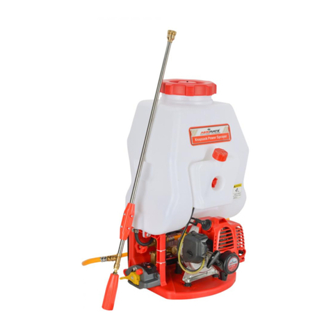
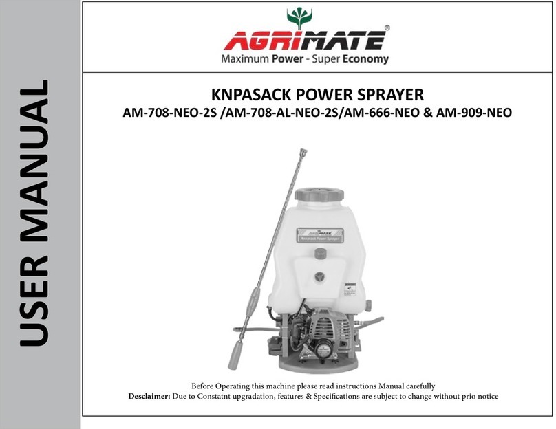
Agrimate AM-K26708 Manual


CONTENTS
INTRODUCTION 2
SAFETYPRECAUTION 2
SPRAYERCOMPONENTS 3
ASSEMBLY 4
STARTING 5
USE–STOPPINGTHEENGINE 6
ENGINEMAINTENANCE–STORAGE 7
PUMPMAINTENANCE 8
TECHNICALDATA 9
WARRANTYCERTIFICATE 10
1

INTRODUCTION
To correctly use the sprayer and prevent accidents, do not start work without having first carefully
read this manual. You will find explanations concerning the operation of the various parts plus
instructions for necessary checks and relative maintenance.
SAFETY PRECAUTIONS
WARNING: If correctly used, the sprayer is a quick, easy to handle and efficient tool: if used
improperly, or without the due precautions it could become a dangerous tool. For pleasant and
safe work, always strictly comply with the safety rules that follow and throughout this manual.
1- The sprayer must be used only by adults with knowledge of the operating instructions.
2- Do not use the sprayer when you are physically tired.
3- Wear gloves, protective glassed and ear protection. Wear long trousers; DO NOT WEAR
short trousers. Wear non-ship footwear; DO NOT work with open sandals or barefooted.
4- Never allow bystanders to remain within your working area.
5- Always work from a firm-footed and safe position.
6- Transport the sprayer with the engine switched off and the liquid tank empty.
7- Do not attempt to service the sprayer while the engine is running.
8- Fill the tank away from sources of heat and with the engine stopped. Never smoke while
filling. Never take the cap off the tank when the engine is running. If fuel spills over while
filling, move the sprayer at least 3 meters (10 ft) away before starting.
9- Before starting, make sure that the liquid cock is closed.
10-Check the sprayer each day to ensure that each device, whether for safety or otherwise, is
functional.
11-Always follow the manufacturer’s instructions for the maintenance operations.
12-Never use a damaged, modified, or improperly repaired or assembled sprayer. Do not remove
or damage any of the safety devices.
13-Never carry out operations or repairs on your own that are other than routine maintenance.
Call specialized and authorized workshops only.
14-Never use fuel for cleaning operations.
15-Keep the sprayer in a dry place, off the ground with the tanks empty.
16-Wear an approved respirator and protective overalls for protection against toxic liquids.
17-Do not operate the sprayer in explosive atmospheres or near inflammable substances. When
spraying in a greenhouse, ensure that the work area is well ventilated.
18-Do not use the sprayer until you have completely understood the specific operating method.
19-It is prohibited to attach a pump or any other implement not supplied by the manufacturer to
the power take – off the pump.
20-If your sprayer is no longer usable, dispose of it carefully without damaging the environment
by handing it into your local Dealer who will arrange for its correct disposal.
21-Only loan your sprayer to expert users who are completely familiar with sprayer operation and
correct use. Give other users the manual with operating instructions, which they should read
before using the sprayer.
22-Keep this manual on hand and consult it before each use of the tool.
23-Do not direct the lance and nozzles towards persons or animals.
24-Never start the machine without pump. It will cause serious damages to the engine parts as
well as the withdrawal of the warranty.
25-Do not use the sprayer set close to electrical equipment.
26-Take the cap off the spark plug each maintenance time, during cleaning or repair work.
27-The sprayer must always be kept upright to prevent liquid escaping from the tank.
28-Do not use the sprayer with inflammable and / or corrosive substances.
29-Do not assemble the pump on other motors or power transmissions.
30-The engine is 2-stroke. Always use mixture for the fuel. Gasoline without oil damages engine
Inashorttime. 2
SPRAYER COMPONENTS
1- Spray gun
2- Cock switch
3- Roller
4- High pressure PVC hose
5- Drain cup
6- Tank cover
7- Liquid tank
8- Fuel cap
9- Fuel tank
Read the operator’s instruction book before operating this machine.
Wear head, eye and ear protection.
3

ASSEMBLY
Assembling the lance:
The sprayer is supplied packaged as shown in
Fig. 1. To prepare the sprayer for use a few
simple operations are required:
- Connect the high pressure hose (Fig 2-A) to
the pump and secure with wing nut (Fig 2-B).
- Screw the jet regulator (Fig 3-C) onto the tip
of the handle (Fig 3-D) and high pressure hose (Fig 2-A).
- Screw the lance (Fig 4-E) onto the control
valve(Fig4-F)
Optional
A range of lances for all operator requirements
can be purchased separately (Fig 5):
- Lance with 2 nozzle (Fig 5-G)
- Lance with 3 nozzle (Fig 5-H)
- Lance with 4 nozzle (Fig 5- I)
Lanceperformance:
The standard lance with single nozzle with the
regulator fully open (turned counter-clockwise)
has a vertical throw of 220cm from the lance tip
(Fig 6).
4
1
2
3
4
MAX
220cm
6
5

STARTING
Fuel Mixture:
Use a 4% (25:1) oil-gasoline mixture.
(oil : two stroke oil or 20/50 engine oil)
Warning: two stroke engines have hing
specific horsepower and we therefore
recommend the use of well known, super
gasoline, with or without lead and an
octane rating of no less than 90. When
preparing the mixture, only use oil for two
stroke engines. Shake the fuel canister
before filling. Refill (Fig 7) when the
engine is switched off and far away from
naked flames. Before unscrewing the fuel
tank cap position the sprayer on a flat,
solid surface to prevent fuel spills. Only
prepare the quantity of mixture for each
job, do not leave the mixture in the fuel
tank or in a fuel canister for prolonged
periods.
Starting the engine:
Make sure that the throttle lever is in the
idle position. Fill the carburetor by
pushing the primer bulb (Fig 8-A). Put the
choke lever (Fig 9-B) in the “CLOSE”
position. Place the sprayer on the ground
in a stable position. Holding the sprayer
firmly (Fig 10), pull sharply on the starter
cord to start the engine. Wait a few
seconds then operate the throttle lever to
release the automatic semi-acceleration
device. The starter lever should return to
its original “OPEN” position.
Warning: once the engine is warmed
up, do not use choke to start up again.
5
7
8
9
10

USE-STOPPING THE ENGINE
USE:
-Fill the liquid tank through the filter
provided to prevent the introduction of
foreign bodies (Fig 11-A)
-Replace the filler cap (Fig 12-B) making
sure it is tightly sealed.
-After starting the engine, adjust the liquid
flow by way of the pressure regulator (Fig
13-C). The regulator can be easily operated
when the sprayer is on the back of the
operator.
-Operate the control valve to control the
Spray (Fig 14-D).
Warning: After starting the sprayer, operate the
control valve immediately to allow any residual air
trapped inside the pump to escape and to check that
the liquid is flowing normally. If the liquid does not
flow normally, operate the pressure regulator to
eliminate air from the pump. Never ever operate
the pump when the liquid tank is empty.
Warning: On completion of work, close the liquid
valve before stopping the engine.
Stopping the engine:
Set the throttle lever to minimum. Switch off the
engine by turning the stop switch to STOP.
Warning: After use of liquid chemicals, flush out
the pump immediately by filling the tank with clean
water and re-starting the sprayer.
6
11
12
13
14

ENGINE MAINTENANCE-STORAGE
Engine maintenance:
Warning: Always wear protective gloves during
maintenance operations. Do not carry out
maintenance when the engine is hot.
Air filter: Every 8-10 working hours, take off the
Cover. The filter should be cleaned by shaking it
Well and with a soft brush (Fig 15).
Fuel filter: Check the fuel filter periodically.
Replace it if too dirty (Fig 16).
Engine: Clean the cylinder fans (Fig 17) with
compressed air or a brush periodically. Dangerous
overheating of engine may occur due to impurities
on the cylinder.
Spark plug: Clean the spark pug and check the
Electrode gap periodically (Fig 18).
Storage: -When the mist blower is stored for long
intervals, use clean water and run sprayer for
few minutes. Dry the sprayer thoroughly,
empty the fuel tank and clean the engine.
-Empty the fuel cap and put the cap back on.
-Remove the spark plug; pour a small amount
Of oil into the cylinder(Fig 19).
-Rotate the crankshaft several times using the
starting rope in order to distribute the oil. Put
the park plug back in.
-Store the pump in a dry place, preferably not
in direct contact with the floor and away from
the hear sources.
-Do not lie the sprayer on its side, oil may leak.
Warning: All maintenance operations not
reported in this manual must be carried out by
an authorized Service Center. To ensure steady
and regular sprayer operation, remember that parts
must only be replaced with original spares.
7
15
16
17
18
20 19
0.5mm
(
0.02”
)
RCJ-6Y

21
22
PUMP MAINTENANCE
Oil- To check the oil level, remove the
protective rubber cushion (Fig 21) by
removing the screws. Change oil firstly after
30 operating hours, then every 100 operating.
1- Unscrew plug (Fig 22-C) and drain oil.
Replace and tighten drain plug.
2- Unscrew breather cap (Fig 20) of the
oil tank and fill with 120cc of SAE 40 or
20/50 engine oil.
Grease nipples-Apply with grease at each
grease nipple (Fig 23-E)
Warning: Screw in the grease nipple two
turns every 2 operating hours.
Valve- To remove the valve (Fig 24-F), for
cleaning, remove the screws (Fig24-G) and
valve cap. Remove any residue from the
valve cap. Change the valve spring (fig 24-
L) if broken or worn.
If the valve looses pressure:
1- Fit a new valve if the pressure
regulator (Fig 24-M) or the valve
seat (Fig 24-N) is worn.
2- Remove any residue from the valve
seat.
3- Renew the oil seals if worn.
Nozzles – Replace the nozzles if broken or if
the y loose pressure (Fig 25).
High pressure hose- Replace the high
pressure hose (Fig 26-K) if broken or worn.
8
23
24
25
26

TECHNICAL DATA
Engine Zenoah G26LS KM26 engine
Displacement cc 25.4 25.6
Power kW 0.81 0.80
Max. rpm min-1 9000
Min. rpm min-1 3000
Fuel tank capacity cm31000
Electronic ignition Yes
Anti-vibration system Yes
Diaphragm carburetor Yes
Primer carburetor Yes
Centrifugal clutch
Max. vertical liquid range
m Yes
2.2
Pump reduction ratio 1÷4
Agricultural chemical solutions
containing acids pH 4 - 9
Prohibited chemical solutions Sulfuric acid, nitric acid,
hydrochloric acid, alkalis, powered &
insoluble chemicals
Liquid discharge 1/min 7.2
Weight Kg 11.2
Dimensions mm 390x330x630
Main tank capacity L 23
pressure Kg/cm235
9

WARRANTY CERTIFICATE
This machine has been designed and manufactured using the most modern techniques. The
manufacturer guarantees the machine to be free from defects for a period of twelve months from the
date of purchase provided it is used exclusively for private/hobby purposes. If the machine is used
for professional purposes, the warranty period shall be for a period of six months. If the machine is
used for hire no warranty. This warranty is only for first owner.
Limited Warranty:
1) The warranty period starts on the date of sale. The manufacturer, acting through the sales and
technical assistance network, shall replace free of charge any parts proven defective in
material, machining and manufacturing. The warranty does not affect the purchaser’s rights as
established under legislation governing the consequences of defects in the machine.
2) Technical personnel will undertake the necessary repairs in the minimum time possible
compatible with organizational needs.
3) To make any claim under the warranty, this certificate of warranty, fully complied,
bearing the dealer’s stamp, and accompanied by the invoice or receipt showing the date
of purchase, must be displayed to the personnel authorized to approve work.
4) The warranty shall be null and void if:
-The machine has evidently not been serviced correctly.
-The machine has been used for improper purposes or has been modified in any way.
-Unsuitable lubricants and fuels have been used.
-Non-original spare parts and accessories have been fitted.
-Work has been done on the machine by unauthorized personnel.
5) The warranty does not cover consumables or parts subject to normal wear.
6) The warranty does not cover work to update or improve the machine.
7) The warranty does not cover any preparation or servicing work required during the warranty
period.
8) Damaged incurred during transport must be immediately brought to the attention of the carrier:
failure to do so shall render null and void the warranty.
9) The warranty does not cover injury or damage caused directly or indirectly to persons or
things by defects in the machine or by periods of extended disuse of the machine resulting
from the said defects.
Model Date
Serial No…………….
Dealer
Bought by Mr.
10

WARNING!!!
RISK OF DAMAGING HEARING
IN NORMAL CONDITIONS OF USE, THIS MACHINE
MAY INVOL VE A DAIL Y LEVEL OF PERSONAL
EXPOSURE TO NOISE FOR THE OPERATOR
EQUALTOORGREATERTHAN
85 dB(A)
WARNING!- This owner’s manual must stay with the machine for all its life.
Model
Pressure Level
Power level
Vibration Level
LpA
EN ISO 11201
LwA
ENISO 3744
EN28662-1
m/s2
25.6cm3
93dB(A)
101dB(A)
<2.5
11
Table of contents
Other Agrimate Paint Sprayer manuals

Agrimate
Agrimate KNPASACK User manual

Agrimate
Agrimate AM22-NT User manual

Agrimate
Agrimate AM-405E-ELITE User manual

Agrimate
Agrimate AM-21K User manual

Agrimate
Agrimate AMP-769-HCP User manual

Agrimate
Agrimate AM-708T User manual

Agrimate
Agrimate AM-708-PRO-2S-WC User manual

Agrimate
Agrimate AM ZOOM User manual

Agrimate
Agrimate AM 22 AUTO User manual

Agrimate
Agrimate AMP-768-PRO 4S Series User manual