manuals.online logo
Brands
  1. Home
  2. •
  3. Brands
  4. •
  5. New Holland
  6. •
  7. Farm Equipment
  8. •
  9. New Holland Harvester 1900 User manual

New Holland Harvester 1900 User manual

NEW HOLLAND
Service Manual
Harvester
1900,2100
Issue 8-89
(Replaces All Previous Issues)
Reprinted
INTRODUCTION
This service manual provides you with the technical information needed to properly service the
1900 and 2100 harvesters. By using this service manual, in addition to the operator's manual
supplied with the harvesters, you should be able to correctly service and maintain the harvesters.
Whenever working on Ford New Holland equipment, left and right sides of the machine are
determined by standing behind the machine, looking in the direction of travel.
This manual details the procedures of removal, disassembly, reassembly, etc., that have been
found to be the easiest and least time-consuming. There may be several other ways of completing
the same job, but it has been established that the detailed methods in this manual are best.
Modifications to these procedures are your own decision.
Certain hardware on the harvesters must be tightened to particular torque specifications. If there
are no specific torque specifications for the hardware, tighten to the torque listed in the front section
of this manual.
Units have been manufactured in several configurations as listed below, so it's important that you
know the harvester's serial number when using this manual:
1900
Serial numbers 440350 and below have a clutch pack reversing gearbox and Metalert® I.
Serial numbers 440351through and including 440385haveaclutch pack reversing gearbox and
Metalert II.
Serial numbers 440386 and above have an electric clutch reversing gearbox and Metalert II.
Serial numbers 500000 and above have an automatic sharpener
2100
Serial numbers 469333 and below have a clutch pack reversing gearbox and Metalert I.
Serial numbers 469334 and above have an electric clutch reversing gearbox and Metalert II.
IMPROVEMENTS
Ford New Holland, Inc. is continually striving to improve its products. We must, therefore,
reserve the right to make improvements or changes when it becomes practical and possible
to do so, without incurring any obligation to make changes or additions to the equipment sold
previously.
ALL SPECIFICATIONS SUBJECT TO CHANGE WITHOUT NOTICE.
368 ©1999 FORD NEW HOLLAND, INC.
Find manuals at https://best-manuals.com
CONTENTS
SAFETY ................................................................... 0-5
STANDARD TORQUE DATA - HYDRAULIC TUBES AND FITTINGS .......... 0-3
HARDWARE KEY .......................................................... 0-4
SECTION 1 - REPLACING MODEL 1900 MAIN DRIVE BELTS ............... 1-1
SECTION 2 - CUTTERHEAD CLUTCH ASSEMBLY ......................... 2-1
SECTION 3 - TRANSFER GEARBOX REPAIR - MODEL 2100 ONLY .......... 3-1
SECTION 4 - CUTTERHEAD GEARBOX REPAIR ........................... 4-1
SECTION 5 - CUTTERHEAD BEARINGS ................................... 5-1
SECTION 6 - CUTTERHEAD AND FEEDROLL ASSEMBLY REMOVAL ....... 6-1
SECTION 7 - REVERSING GEARBOX REPAIR .............................. 7-1
SECTION 8 -BLOWER AND SPOUT ASSEMBLY ........................... 8-1
SECTION 9-FEEDROLLS AND FEEDROLL DRIVE REPAIR ................. 9-1
SECTION 10 - GROUND DRIVE TRANSMISSION ......................... 10-1
SECTION 11 - FINAL DRIVE REPAIR ..................................... 11-1
SECTION 12-ATTACHMENT FLOTATION SYSTEM ...................... 12-1
SECTION 13- HYDRAULIC SYSTEM ..................................... 13-1
SECTION 14- HYDROSTATIC SYSTEM .................................. 14-1
SECTION 15 - POWERED REAR AXLE ................................... 15-1
SECTION 16- ELECTRICAL SYSTEM .................................... 16-1
SECTION 17 - METAL DETECTOR ....................................... 17-1
INDEX .................................................................. 17-48
0-1
Find manuals at https://best-manuals.com
PRECAUTIONARY
STATEMENTS
PERSONAL SAFETY
Throughout this manual and on machine decals, you will find precautionary statements
("CAUTION", "WARNING", and "DANGER") followed by specific instructions. These
precautions are intended for the personal safety of you and those working with you.
Please take the time to read them.
A
CAUTION: THE WORD "CAUTION" IS USED WHERE A SAFE BEHAVIORAL PRACTICE
ACCORDING TO OPERATING AND MAINTENANCE INSTRUCTIONS AND COMMON
SAFETY PRACTICES WILL PROTECT THE OPERATOR AND OTHERS FROM
ACCIDENT INVOLVEMENT.
A
WARNING: THE WORD "WARNING" DENOTES A POTENTIAL OR HIDDEN HAZARD
WHICH HAS A POTENTIAL FOR SERIOUS INJURY. IT IS USED TO WARN OPERATORS
AND OTHERS TO EXERCISE EVERY APPROPRIATE MEANS TO AVOID A SURPRISE
INVOLVEMENT WITH MACHINERY.
A
DANGER: THE WORD "DANGER" DENOTES A FORBIDDEN PRACTICE IN
CONNECTION WITH A SERIOUS HAZARD.
FAILURE TO FOLLOW THE "CAUTION", "WARNING", AND "DANGER"
INSTRUCTIONS MAY RESULT IN SERIOUS BODILY INJURY OR DEATH.
MACHINE SAFETY
Additional precautionary statements ("ATTENTION" and "IMPORTANT") are followed
by specific instructions. These statements are intended for machine safety.
ATTENTION: The word "ATTENTION" is used to warn the operator of potential machine
damage if a certain procedure is not followed.
IMPORTANT: The word "IMPORTANT" is used to inform the reader of something he
needs to know to prevent minor machine damage if a certain procedure is not followed.
0-2
Find manuals at https://best-manuals.com
STANDARD TORQUE DATA
FOR HYDRAULIC TUBES AND FITTINGS
TUBE NUTS
FOR 37° FLARED FITTINGS 0-RING BOSS PLUGS,
ADJUSTABLE FITTING
LOCK NUTS, SWIVEL
JIC -37° SEATS
TORQUE TORQUE
TUBING THREAD FOOT NEWTON FOOT NEWTON
SIZE O.D. SIZE POUNDS METERS POUNDS METERS
Inches mm Min. Max. Min. Max. Min. Max. Min. Max.
4 1/4 6.4 7/16-20 9 12 12 16 6 10 8 14
5 5/16 7.9 1/2-20 12 15 16 20 10 15 14 20
6 3/8 9.5 9/16-18 21 24 29 33 15 20 20 27
8 1/2 12.7 3/4-16 35 40 47 54 25 30 34 41
10 5/8 15.9 7/8-14 53 58 7'?. 79 35 40 47 54
12 3/4 19.1 1-1/16-12 77 82 104 111 60 70 81 95
14 7/8 22.2 1-3/16-12 90 100 122 136 70 80 95 109
16 1 25.4 1-5/16-12 110 120 149 163 80 90 108 122
20 1¼ 31.8 1%-12 140 150 190 204 95 115 129 156
24 1½ 38.1 1¾-12 160 175 217 237 120 140 163 190
32 2 50.8 2½-12 225 240 305 325 250 300 339 407
Above torque figures are recommended for plain, cadmium or zinc plated fittings, dry or wet
installations.
Swivel nuts either swaged or brazed.
These torques are not recommended for tubes of½" (12.7 mm) 0.D. and larger with wall thickness of
0.035" (0.889 mm) or less. The torque is specified for 0.035" (0.889 mm) wall tubes on each
application individually.
0-3
Find manuals at https://best-manuals.com
HARDWARE KEY
®
JAIi
NUT
~~
STANDARD SELF•
~
'1~~~
GRADE5 NUT FLANGE· CARRIAGE SHORT NECK
NUT LOCKING
NUT CAPSCREW HEAD BOLT CARRIAGEBOLT
BOLT
Cap Screw - CS
Carriage Bolt - CB
Short Neck Carriage Bolt - SNCB
Flat Washer - FW
Lock Washer - LW
Lock Nut - LN
Regular Nut - N
Jam Nut -JN
National Fine Thread - N.F.
Grade 5 - GR. 5
Grade 8 - GR. 8
Cotter Pin - CP
Machine Screw - MS
Flange Nut - FN
Flange Head Bolt -FHB
STAINLESS
STEEL BOLT
(TORQUE-USE
GRADES
SPECIFICATIONS)
MINIMUM HARDWARE TIGHTENING TORQUES
IN FOOT POUNDS (NEWTON-METRES) FOR NORMAL ASSEMBLY APPLICATIONS
OGRADE 2 e GRADE 0 © GRADE 8
SAE 5 SAE
SAE
Bolt Unplated or Unplated Plated Unplated Plated
Size Plated
1/4" 5 ( 7) 8 ( 11) 7 ( 9) 12 ( 16) 10 ( 13)
5/ 16" 10 ( 13) 18 ( 24) 15 ( 20) 26 ( 35) 21 ( 28)
3/8" 18 ( 24) 31 ( 42) 25 ( 34) 48 ( 65) 39 ( 53)
7/ 16" 31 ( 42) 53 ( 72) 43 ( 58) 75 ( 1
o1l 60 ( 81)
1/2" 45 ( 61) 82 (111) 66 ( 89) 115 ( 155) 92 (124)
5/8" 82 (111) 170 (230) 140 (189) 235 ( 317) 190 (256)
3/4" 155 (209) 290 (392) 230 (310) 415 ( 560) 330 (445)
7/8" 165 (223) 430 (580) 340 (459) 600 ( 810) 4ao (648)
1" 250 (337) 640 (864) 510 (688) 900 (1215) 720 (972)
0-4
Find manuals at https://best-manuals.com
A
SAFETY
YOUR SAFETY IS OF UTMOST CONCERN TO FORD NEW HOLLAND, PLEASE FOLLOW
THE SAFETY RULES LISTED, NOT ONLY FOR YOUR OWN GOOD, BUT FOR THE PEOPLE
AROUND YOU.
1. DO NOT ALLOW CHILDREN OR BYSTANDERS AROUND THE MACHINE WHILE IT IS BEING
ADJUSTED, SERVICED, OR OPERATED.
2. ALWAYS USE A SAFETY STAND IN CONJUNCTION WITH HYDRAULIC JACKS OR HOISTS.
DO NOT RELY ON THE JACK OR HOIST TO HOLD THE LOAD COMPLETELY, AS THEY
COULD FAIL.
3. ALWAYS WEAR SAFETY GLASSES WHEN USING A HAMMER, CHISEL, OR OTHER TOOLS
THAT MAY CAUSE CHIPS TO FLY OFF THE WORK.
4. KEEP WORK ORGANIZED AND CLEAN. WIPE UP OIL SPILLS OF ANY KIND TO MINIMIZE
THE POSSIBILITY OF A FALL. KEEP TOOLS AND PARTS OFF THE FLOOR TO FURTHER
REDUCE THE POSSIBILITY OF SERIOUS INJURY.
5. BE SURE TO REINSTALL SAFETY DEVICES SUCH AS GUARDS OR SHIELDS AFTER
ADJUSTING OR SERVICING THE HARVESTER.
6. AFTER SERVICING THE HARVESTER, BE SURE ALL TOOLS, PARTS, OR SERVICING
EQUIPMENT ARE REMOVED FROM THE MACHINE.
7. WHEN USING A GAS TORCH, ALWAYS WEAR WELDING GOGGLES AND GLOVES. KEEP A
FULLY CHARGED FIRE EXTINGUISHER WITHIN REACH. DO NOT HEAT OR WELD NEAR A
FUEL TANK OR FUEL LINES, AND UTILIZE PROPER SHIELDING AROUND HYDRAULIC
LINES.
8. ELECTRIC STORAGE BATTERIES GIVE OFF HIGHLY FLAMMABLE GAS WHEN CHARGING,
AND CONTINUE TO DO SO FOR SOME TIME AFTER RECEIVING A STEADY CHARGE. DO
NOT UNDER ANY CIRCUMSTANCES ALLOW AN ELECTRIC SPARK OR FLAME NEAR THE
BATTERY. ALWAYS DISCONNECT THE BATTERY FIRST BEFORE WORKING ON THE
ELECTRIC SYSTEM.
9. HYDRAULIC FLUID ESCAPING UNDER PRESSURE CAN HAVE ENOUGH FORCE TO
PENETRATE THE HUMAN SKIN. HYDRAULIC FLUID MAY INFECT A MINOR CUT OR
OPENING IN THE SKIN. IF INJURED BY ESCAPING FLUID SEE A DOCTOR AT ONCE. DO
NOT ATTEMPT TO REPAIR OR TIGHTEN HOSES THAT ARE UNDER PRESSURE. CYCLE
ALL HYDRAULIC CONTROL VALVES TO RELIEVE ALL PRESSURE BEFORE DISCON-
NECTING THE LINES OR BEFORE PERFORMING OTHER WORK ON THE HYDRAULIC
SYSTEM. MAKE SURE ALL CONNECTORS ARE TIGHT AND HOSES AND LINES ARE IN
GOOD CONDITION BEFORE APPL YING PRESSURE TO THE SYSTEM. TO LOCATE A LEAK
UNDER PRESSURE, USE A SMALL PIECE OF CARDBOARD, NEVER USE YOUR HANDS.
10. USE PULLERS TO REMOVE BEARINGS, BUSHINGS, CYLINDER SLEEVES, ETC. USE
HAMMERS, PUNCHES, AND CHISELS ONLY WHEN ABSOLUTELY NECESSARY AND BE
SURE TO WEAR SAFETY GLASSES.
11. BE CAREFUL WHEN USING COMPRESSED AIR. USEAPPROVED AIR BLOW GUNS, DO NOT
EXCEED 35 PSI (2.4 BAR), WEAR SAFETY GOGGLES, AND USE PROPER SHIELDING TO
PROTECT EVERYONE IN THE WORK AREA.
12. DO NOT WEAR RINGS, WRIST WATCHES, OR LOOSE FITTING CLOTHING WHEN
WORKING ON MACHINERY, AS THEY COULD CATCH ON MOVING PARTS AND CAUSE
SERIOUS INJURY. WEAR STURDY WORK SHOES.
THE ABOVE IS ONLY A PARTIAL LIST OF SAFETY WORK RULES. IN ADDITION, ALWAYS
REFER TO THE OPERATOR'S MANUAL FOR ADDITIONAL SAFE WORK RULES REGARDING
THIS MACHINE.
0-5
Find manuals at https://best-manuals.com
SECTION 1
REPLACING MODEL 1900 MAIN DRIVE
BELTS
SHIELDS SHOWN OPEN FOR CLARITY.
SPECIAL TOOLS - None
'
REMOVAL
1. Remove the belt tension spring, A, Figure
1-1, and the shock absorber, B.
2. Remove the hydraulic pump drive belt, C,
Figure 1-1.
3. Remove the hydraulic pump drive belt idler,
A, Figure 1-2, by removing the cotter pin, B,
and unbolting the mounting bracket, C.
4. There will be more access for changing
belts if the right side shield is removed.
Remove the shield by removing the bolts,
B, Figure 1-3.
1-1
FIGURE 1-1
Find manuals at https://best-manuals.com
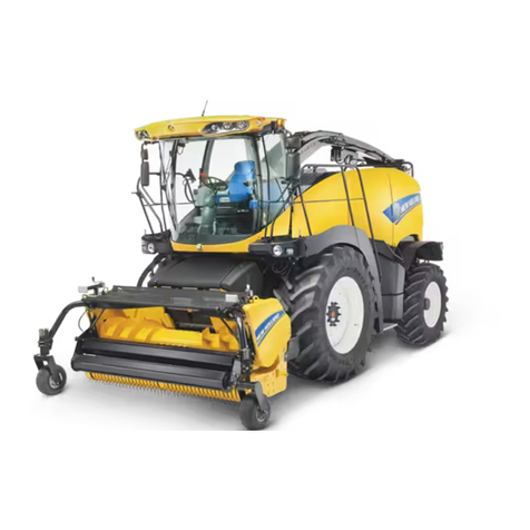
FIGURE 1-2
FIGURE,1-3
1-2
Find manuals at https://best-manuals.com
SHIELDS SHOWN OPEN FOR CLARITY. FIGURE 1-4
5. Remove the spacer block, A, Figure 1-4, in
the hydrostatic pump drive. Slide the rear
hub, B, off the hydrostatic pump splined
shaft.
6. Remove the latch at C, Figure 1-4.
NOTE: It may be necessary to remove the
right front engine mount to remove bolt, B,
figure 1-6. See step 7.
7. Position a½" x 1¼" cap screw and nut at A,
Figure 1-5. Adjust the nut so the cap screw
supports the engine. The cap screw and nut
will act as a screw jack. Remove the right
forward engine mount, B, and brace, C,
Figure 1-5.
8. Remove bolt, A, Figure 1-6 on both sides of
the idler. Remove the idler by removing
bolt, B.
NOTE: Early model machines may not have
a brace on the Idler.
9. Remove the idler arm.
10. Remove the belts as shown in Figure 1-7.
DRIVE BELT INSTALLATION
Before installing belts, check and service the
following as needed. Refer to the appropriate
section for information.
A. Engine drive shaft end-play
B. Main drive idler bearings
C. Shock absorber
D. Hydraulic pump drive belt idler
1-3
SHIELDS SHOWN OPEN FOR CLARITY. FIGURE 1-5
E. Hydrostatic pump shaft and drive hub
splines
F. Driven sheave assembly bearings
Assembly is the reverse of disassembly.
SHIELDS SHOWN OPEN FOR CLARITY. FIGURE 1-6
SHIELDS SHOWN OPEN FOR CLARITY.
NOTE: Replace belts only as matched sets.
It may be necessary to remove the engine
sheave to install the new belts. The sheave is
drilled and tapped for½" cap screws.
SHIELDS SHOWN OPEN FOR CLARITY. FIGURE 1-8
1-4
FIGURE 1-7
To remove the sheave, remove the cap screw
and flat washer at A, Figure 1-8 holding the
sheave on the shaft. Install a puller as shown in
Figure 1-9 and remove the sheave from the
tapered spline. When reinstalling the sheave,
torque the mounting bolt to 140 ft. lbs. (190
N·m).
BELT TENSION ADJUSTMENT
Main Drive Belt
NOTE: Two different springs have been used
on the main drive belt Idler.
#49722 spring (1¾" diameter) should be ad-
justed to 11
¾" (30 cm) between the hooks.
#602914 spring (2" diameter) should be ad-
justed to 12¾" (32 cm) between the hooks.
Hydraulic Pump Belt
Adjust the idler spring to a length of 13" (33
cm) between the hooks.
MODEL 1900 ENGINE DRIVE ASSEMBLY
REPAIR
SHIELDS SHOWN OPEN FOR CLARITY. FIGURE 1-9
SPECIAL TOOLS -Three 3/e" x 3" headless
bolts
REMOVAL
1. Remove the drive belts (see "Replacing
Model 1900 Main Drive Belts").
2. Remove the drive sheave, L, Figure 1-11.
See Figure 1-9. The sheave is tapped for½"
bolts for using a puller.
3. Install three %" x 3" headless bolts as
shown at A, Figure 1-10. This will prevent
damage to the drive blocks, C, Figure 1-11,
during removal and installation.
4. Remove the drive assembly. NOTE: Use a
support as the assembly Is heavy.
DISASSEMBLY (Figure 1-11)
1. Remove the drive spacer, B. The spider is
tapped for using a puller.
1-5
""'"-'---· '
m;m .. - a:;
~
,n,,, '..:.li 't",W "~i ,,-;_ ,,.::,-,
s,,,cm - ''"'" -I 'IVI ',.,,.. ,,.-. ,, 1 ,_1 'Y/' ,...,,,
o<c<ll ,,_ -,. 't«ol ._...,,. '•fl hl:I ,.d ,,,.,. .,:,,., ,I.._ s:-,,
i;:WJ
~
..... "Al ,H'.J ,'!'~! ,; ; ;.,r,;:• :.t.: fllf, V;'.-1:
'<'ff~ ,_ ••• .. ,. ,.-,,1 ...,.. '•'"• ', ,~ ,-/~I _. ••:,, -
wa .- .-:111 .:ci:,
~
-1 .. ..._,.., .,1111 '°" -1..,. -•
um .. - u. - .,. -
~
SHIELDS SHOWN OPEN FOR CLARITY. FIGURE 1-10
2. Remove the bearing cap, H. The shaft will
slide out.
PARTS INSPECTION
Drive Blocks
Replace if scuffed or worn.
ASSEMBLY NOTES (Refer to Figure 1-11)
1. It is possible to install the shaft backward.
The end of the shaft where the drive spider
mounts measures 3-13/16" (9.7 cm) to the
bearing shoulder. If the shaft is installed
backward, the sheave will contact the
housing.
2. Shim the shaft for .005" - .008" (.13-.2 mm)
end-play. The shims are .005" (.13 mm),
.0075" (.2 mm).
3. Install seal, D, as shown.
4. The idler pivot shaft, N, is replaceable on
later model 1900 harvesters.
0
L--....i
M F
1-6
I
.----,
I 1.,.._ __ C
I I
I I
I
I
I
I I
,---'
FIGURE 1-11
FIGURE 1-11 INSTALLATION
A.
B.
C.
D.
E.
F.
G.
H.
I.
J.
K.
L.
M.
N.
Housing
Drive spider
Drive blocks
Seal
Bearing cup
Bearing cone
Shims
Bearing cap
Seal
Bearing cone
Bearing cup
Sheave
Shaft
Idler pivot
Installation of the assembly is the reverse of
removal. Becareful not to lose any of the rubber
blocks.
MODEL 1900 SHEAVE AND
DRIVE RING ASSEMBLY
REPAIR
SHIELDS SHOWN REMOVED FOR CLARITY. FIGURE 1-12
1-7
SHIELDS SHOWN OPEN FOR CLARITY. FIGURE ·1-13
SHIELDS SHOWN REMOVED FOR CLARITY.
1-8
SPECIAL TOOLS -See figure 1-19.
REMOVAL
The sheave and drive ring assembly is easily
serviced by removing it and the cutterhead
clutch assembly as a unit.
1. Remove shields over the clutch assembly.
2. Remove main drive belt (see "Replacing
Main Drive Belts").
3. Remove the drive shaft to the cutterhead
gearbox by removing the driveline shear
bolts and unbolting the shaft at A, Figure
1-13.
4. Remove the cutterhead clutch cable and
mounting bracket, A, Figure 1-12. Remove
the blower belt, B, and the support bracket,
C, Figure 1-12.
5. Remove the hydrostatic control cable and
mounting bracket, A, Figure 1-14. Remove
the cap screws at B, Figure 1-14, holding
the high pressure tube mounting brackets.
FIGURE 1•14
SHIELDS SHOWN REMOVED FOR CLARITY.
Support the hydrostatic pump with a hoist
and remove the four mounting bolts at C,
Figure 1-14. Slide the pump rearward and
support it as shown in Figure 1-15.
6. Support the sheave housing and clutch
assembly as shown in Figure 1-16. Remove
the six cap screws holding the assembly to
the frame. Lift off the assembly.
7. Remove the cap screws holding the clutch
assembly to the sheave housing. Remove
the clutch assembly. Be careful to pull the
assembly straight out to avoid damaging
the fiber gears.
1-9
FIGURE 1-15
FIGURE 1-16
SHIELDS SHOWN REMOVED FOR CLARITY.
FIGURE 1-11
FIGURE 1-17
A. Sheave
B. Washer
C. Shaft
D. Bearing cap
E. Bearing cup
F. Bearing cone
G. Seal
H. Pilot bearing
I. Nut
J. Locking tab
K. Drive ring assembly
L. Bearing cup
M. Shims
DISASSEMBLY
(Refer to Figures 1-17 and 1-18)
1. Remove the pilot bearing, H, Figure 1-17.
2. Remove the nut, I. The shaft can be pre-
vented from turning by bolting a bar to the
sheave asshown in Figure 1-18. See Figure
1-19 for dimensions of bar.
3. Remove the locking tab, J, and use a puller
to remove the drive ring, 11. The ring is
tapped for a puller.
4. Loosen the drive sheave hardware using
the bar in Step 2 to hold the sheave. Then
remove the housing around the sheave.
Remove the sheave.
5. Remove the bearing cap and the shaft will
slide out.
ASSEMBLY NOTES (Refer to Figure 1-17)
NOTE: Pack the bearings with grease before
assembling.
1. Shim the bearing cap for ashaft end-play of
.003" to .005" (.08 mm-.13 mm). The shims
are .005" (.13 mm), .0075" (.19 mm), and
.020" (.51 mm).
2. Install seal, G, as shown.
3. Install the sheave and tighten the cap screw
to 140 ft. lbs. (190 N·m).
4. Install the "C" housing.
5. Install the bar, Figure 1-19, and then install
the drive ring.
1-11
SHIELDS SHOWN OPEN FOR CLARITY. FIGURE MB
FIGURE 1-19
Tighten nut, 1,holding the drive ring to 275
to 285ft. lbs. (373-386 N·m). Then strike the
hub of the drive ring several times to seat
the splines. Re-torque the nut. Bend the
locking tab, J, against the nut.
INSTALLATION
1. Install the sheave and drive ring assembly
on the cutterhead clutch assembly. Be
careful when mating the fiber gears to the
drive ring to not damage the gears.
2. Lift the assembly into place as shown in
Figure 1-16, and install but do not tighten
the mounting hardware.
3. Remove the supporting chain to the rear
"C" housing and then remove the "C"
housing, A, Figure 1-16.
SHIELDS SHOWN REMOVED FOR CLARITY.
SHIELDS SHOWN OPEN FOR CLARITY. FIGURE 1-21
1-12
FIGURE 1-20
4. Align the sheaves by shifting the assembly
in the slotted mounting holes. Reinstall the
belts as shown in Figure 1-20.
5. Reinstall the "C" housing.
6. Install the hydrostatic pump and then install
the flange, A, and spacer, B, Figure 1-21.
Tighten all hardware.
IMPORTANT: Follow Step #6 as detailed to
insure proper alignment of the shafts.
7. Install the hydrostatic control cable and
support. NOTE: When Installing the cable,
position the control lever In the cab In
neutral. Adjust the cable at A or B, Figure
1-22, so the mounting bolt, C, wm Install
without forcing.

This manual suits for next models

1

Other New Holland Farm Equipment manuals

New Holland CX720 Operating instructions

New Holland

New Holland CX720 Operating instructions

New Holland FR480 Forage Cruiser User manual

New Holland

New Holland FR480 Forage Cruiser User manual

New Holland CR920 Operating instructions

New Holland

New Holland CR920 Operating instructions

New Holland FR Manual

New Holland

New Holland FR Manual

New Holland PL6011 User manual

New Holland

New Holland PL6011 User manual

New Holland P2070 User manual

New Holland

New Holland P2070 User manual

New Holland H8060 User manual

New Holland

New Holland H8060 User manual

New Holland MaizeMaster 9105-24 User manual

New Holland

New Holland MaizeMaster 9105-24 User manual

New Holland TC48DA Operating instructions

New Holland

New Holland TC48DA Operating instructions

New Holland D150B User manual

New Holland

New Holland D150B User manual

New Holland CX8080 User manual

New Holland

New Holland CX8080 User manual

New Holland 9040L User manual

New Holland

New Holland 9040L User manual

New Holland CR8.90 User manual

New Holland

New Holland CR8.90 User manual

New Holland BB1290 User manual

New Holland

New Holland BB1290 User manual

New Holland H9870 User manual

New Holland

New Holland H9870 User manual

New Holland SF550 Operating instructions

New Holland

New Holland SF550 Operating instructions

New Holland 9090X User manual

New Holland

New Holland 9090X User manual

New Holland TX62 User manual

New Holland

New Holland TX62 User manual

New Holland MegaCutter 512 User manual

New Holland

New Holland MegaCutter 512 User manual

New Holland 330GM User manual

New Holland

New Holland 330GM User manual

New Holland W130D User manual

New Holland

New Holland W130D User manual

New Holland MZ19H Operating instructions

New Holland

New Holland MZ19H Operating instructions

New Holland 16LA User manual

New Holland

New Holland 16LA User manual

New Holland T8010 User manual

New Holland

New Holland T8010 User manual

Popular Farm Equipment manuals by other brands

APV ZS 200 M3 Original operating instructions

APV

APV ZS 200 M3 Original operating instructions

MASSEY FERGUSON 1843S Workshop service manual

MASSEY FERGUSON

MASSEY FERGUSON 1843S Workshop service manual

Nobili NF 2000 Operator's manual

Nobili

Nobili NF 2000 Operator's manual

Clarke STRONG-ARM CST6 Assembly & user instructions

Clarke

Clarke STRONG-ARM CST6 Assembly & user instructions

Bosch T1657 Operating/safety instructions

Bosch

Bosch T1657 Operating/safety instructions

Kubota AP-SGM1566 Operator's manual

Kubota

Kubota AP-SGM1566 Operator's manual

horsch SW 600 owner's manual

horsch

horsch SW 600 owner's manual

Original inside EUROTOP 701 A Operator's manual

Original inside

Original inside EUROTOP 701 A Operator's manual

PRONAR T669/1 Operator's manual

PRONAR

PRONAR T669/1 Operator's manual

Iluminar ILUM-DE-N1K user manual

Iluminar

Iluminar ILUM-DE-N1K user manual

Kerbl buddex 1716 user guide

Kerbl

Kerbl buddex 1716 user guide

Standen POWAVATOR 150 manual

Standen

Standen POWAVATOR 150 manual

AGCO FENDT 700 Vario SCR Stage 3B Workshop service manual

AGCO

AGCO FENDT 700 Vario SCR Stage 3B Workshop service manual

Reinke Ontrac Installation and service manual

Reinke

Reinke Ontrac Installation and service manual

Titan Implement 9300BU Series Operation and parts manual

Titan Implement

Titan Implement 9300BU Series Operation and parts manual

Baselier FA W Series Operator's manual & parts list

Baselier

Baselier FA W Series Operator's manual & parts list

Finn HydroSeeder T30 Parts and Operator's Manual

Finn

Finn HydroSeeder T30 Parts and Operator's Manual

FASTERHOLT FM4400 User	manual & spare parts catalogue

FASTERHOLT

FASTERHOLT FM4400 User manual & spare parts catalogue

manuals.online logo
manuals.online logoBrands
  • About & Mission
  • Contact us
  • Privacy Policy
  • Terms and Conditions

Copyright 2025 Manuals.Online. All Rights Reserved.