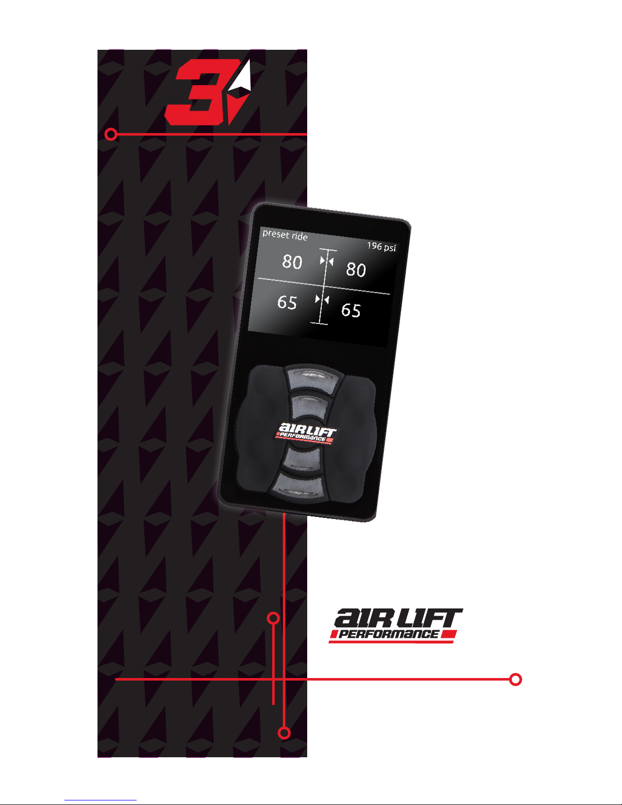
Air Lift Performance 3H User manual

PATENTED
Air Lift
Performance
3H /3P
™
Control System
For maximum effectiveness and safety,
please read these instructions completely
before operating.
Failure to read these instructions can result in an
incorrect installation.
USER GUIDE
MN-948 • (041808) • ECR 9097
PATENTED

Download the App for
the Best #lifeonair
The Air Lift Performance 3 mobile app allows
for full integration of your new 3H/3P control
system on compatible mobile devices. Simply
download the FREE app to not only take full
control of your system, but to always have the
latest system firmware with updates directly
from the app.
For iPhone: air-lift.co/3app
For Android: air-lift.co/android
Users can also search “Air Lift Performance”
in either the Apple App Store or Google Play.
See page 9 for instructions on pairing your
device.

TABLE OF CONTENTS
Introduction .................................... 4
Important Safety Notices ....................................4
Main Controls ....................................5
Quick Reference Guide.............................6
Getting Started ...................................7
Display ..........................................8
Operation ........................................9
Setup ..........................................10
Calibration ......................................12
Calibration Detail Explained........................14
Firmware Updates................................16
Additional Information ............................18
About ..........................................19
System Messages ................................20
Integrated Diagnostics .....................................22
VIAIR Duty Cycle/Working Pressure .................23

4MN-948
3H/3P User Guide
Introduction
The purpose of this publication is to assist with the calibration,
maintenance, and troubleshooting of the Air Lift Performance 3P or 3H
control systems.
Read the entire user guide before beginning calibration or performing
any maintenance, service or repair. The information includes a step-by-
step calibration set-up, display options and functions, and diagnostic
troubleshooting.
Air Lift Company reserves the right to make changes and improvements to
its Air Lift Performance products and publications at any time. For the latest
version of this User Guide, contact Air Lift Company at (800) 248-0892 or
visit www.airliftperformance.com.
IMPORTANT SAFETY NOTICES
BEFORE SERVICING THE VEHICLE, MAKE SURE TO TURN
OFF “RISE ON START” AND “PRESET MAINTAIN.” THIS WILL
ELIMINATE ANY UNINTENDED SUSPENSION CYCLING IF YOU
NEED TO TURN THE KEY ON IN THE VEHICLE FOR ANY REASON.
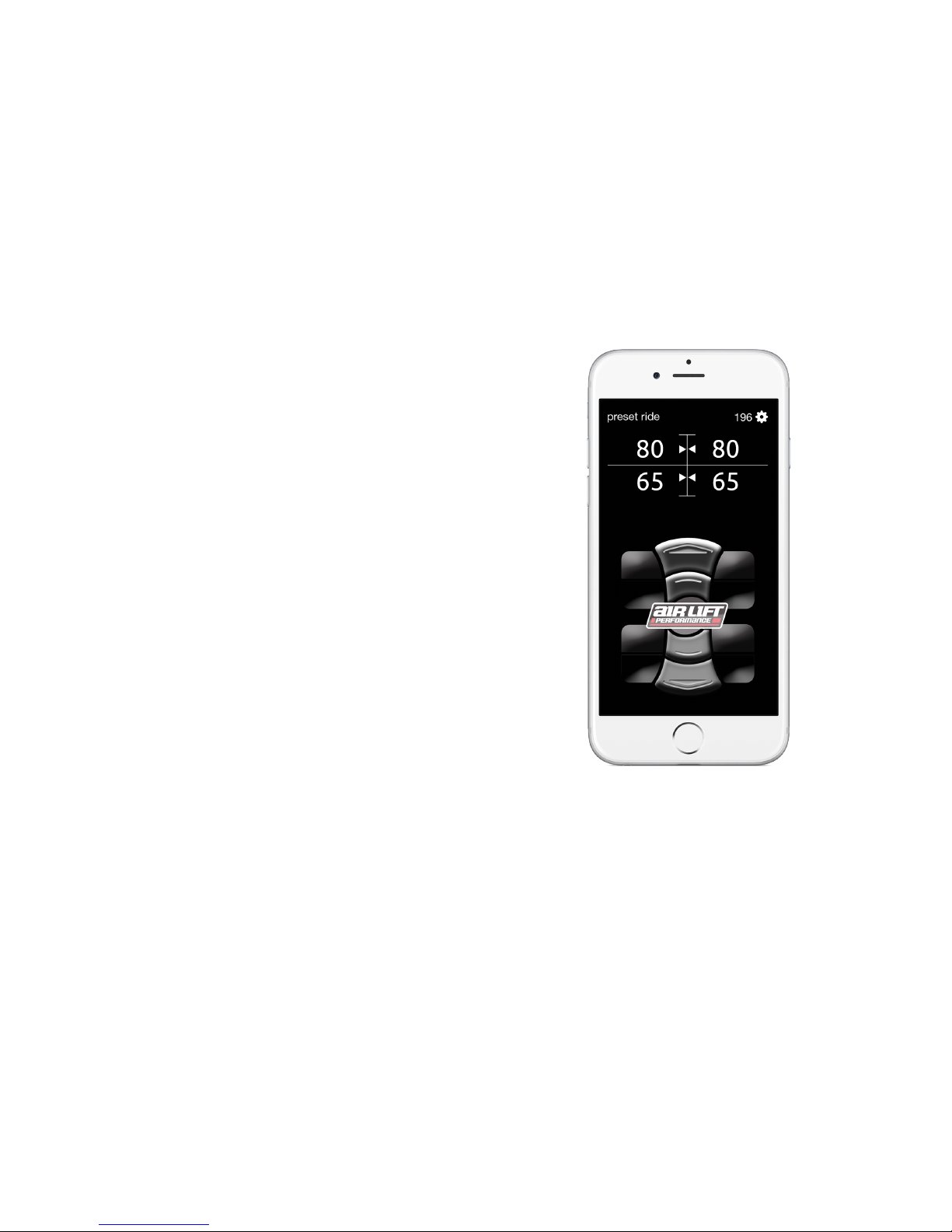
ONLY USE THE AIR LIFT PERFORMANCE 3 APP ON A MOBILE
DEVICE WHEN THE VEHICLE IS IN A CLEAR LINE OF SIGHT. TO
AVOID THE RISK OF SERIOUS INJURY OR HARM, VERIFY THAT
NO PERSON OR THING IS NEAR OR IN THE WAY OF THE VEHICLE’S PATH OF TRAVEL WHILE
CYCLING THE SUSPENSION.
FOR USER SAFETY AND TO PREVENT VEHICLE DAMAGE,
THE SYSTEM HAS A 25% OR 25 PSI (1.7BAR) MINIMUM
DRIVE HEIGHT AS THE DEFAULT. DUE TO EXTREME RISK OF
DANGER TO THE USER OR VEHICLE, AIR LIFT COMPANY STRONGLY RECOMMENDS
NOT TO CHANGE THIS VALUE. IF FOR SOME REASON THE MINIMUM DRIVE HEIGHT IS
SET BELOW THE DEFAULT VALUE, AIR LIFT COMPANY SUGGESTS THIS SETTING ONLY
BE USED WHILE THE VEHICLE IS STATIONARY. IT IS POSSIBLE TO SET THE VEHICLE AT A
HEIGHT THAT IS BELOW THIS THRESHOLD, THEN START DRIVING. THIS IS A UNIVERSAL
SYSTEM AND SETTINGS WILL BE DIFFERENT FOR EVERY USER AND VEHICLE. THE
INSTALLER IS RESPONSIBLE TO DETERMINE HOW LOW THE SUSPENSION CAN BE SET
WITHOUT CAUSING DAMAGE. IT IS THE SOLE RESPONSIBILITY OF THE USER, AND AIR
LIFT COMPANY WILL NOT BE HELD LIABLE FOR, ANYTHING THAT MAY HAPPEN TO THE
OPERATOR OR THE VEHICLE AS A RESULT OF THE USER’S CHOICE TO ALTER THESE
DEFAULT VALUES BELOW RECOMMENDED MINIMUMS.
FLOOR JACKS CAN BE DANGEROUS. WHENEVER USING
A FLOOR JACK, MAKE SURE IT IS RATED FOR THE LOAD IT
IS LIFTING. CHECK THE VEHICLE OWNER’S MANUAL FOR
INFORMATION ABOUT WHERE TO PLACE THE JACK. BEFORE RAISING THE VEHICLE,
PLACE WHEEL CHOCKS IN FRONT AND BEHIND THE WHEELS TO PREVENT THEM FROM
ROLLING. ALWAYS USE JACK STANDS TO SUPPORT THE VEHICLE. NEVER GET UNDER OR
PLACE ANY BODY PARTS UNDER A VEHICLE THAT IS SOLELY SUPPORTED BY THE JACK.
WARNING
WARNING
WARNING
WARNING

5
MN-948
3H/3P User Guide
Front Left Bag
Pressure
Rear Left Bag
Pressure
Mode Indicator
Tank pressure
Front Right Bag
Pressure
Rear Right Bag
Pressure
User-defined
Button
(See Page 7
All-Up Button)
Manually increase
and decrease front
right bag pressure.
Manually increase
and decrease front
left bag pressure.
Manually increase
and decrease rear
right bag pressure.
Manually increase
and decrease rear
left bag pressure.
Preset High
(Up Button)
Preset Ride
(Middle Button)
User-defined
Button
(See Page 7
All-Down Button)
Preset Low
(Down Button)
Main Controls
System Messages
Fault Indicator

6MN-948
3H/3P User Guide
Quick Reference Guide
Main Menu
Screen Sub-Menu Data Default
Display
Brightness Level 1-10 Level 7
Brightness Sleeping Level 1-10 Level 4
Sleep Time 5-60 Sec 10 Sec
All-Up Button
All-Up
All Up
Front-Up
Rear-Up
All-Down Button
All-Down
All Down
Front-Down
Rear-Down
Units PSI PSI
BAR
Operation
Rise-on-Start Off Off
On
Pre-Set Maintain Off Off
On
Minimum Drive Height 0-100 PSI (Pressure)
0-100% (Height) 25 PSI / 25%
Pressure/Height Mode Height Pressure
Pressure
Anti Cross-Load (Height)
Axle Equalization
(Pressure)
Off
On
On
Show Mode Off Off
On
Bluetooth Pairing Off Off
On
Setup
Sensor Tool See Page 10 —
Compressor See Compressor
Main Menu —
Min. Battery (Voltage
to allow compressor
to still run)
10-15 Volts 11 Volts
Factory Reset Cancel Cancel
Reset All
Compressor
On/Off Off Off
On
Enable/Disable Enabled Enabled
Disabled
Dual/Single Single Single
Dual
Max Pressure 150-200 PSI
(10342-13789mBAR) 150 PSI (10342mBAR)
Duty Cycle
33%
50%
50%
66%
75%
100%
Calibration Wizard See Page 12 —

7
MN-948
3H/3P User Guide
Getting Started
This User Guide is designed to demonstrate
all the different menu options and default
settings that will help make using this
system easy and enjoyable.
1. To get to the main menu screen,
push the middle (preset ride) button
simultaneously with either the up (preset
high) button or down (preset low)
button.
2. All other settings
and parameters will
be detailed in the
following pages to
ensure the system is
set up accurately.
3. Use the preset low
and preset high
buttons to scroll.
4. Green text indicates the last saved
value.
User-defined button
Preset high (up)
Preset ride (middle)
Preset low (down)
User-defined button

8MN-948
3H/3P User Guide
Display
BRIGHTNESS
Set the brightness for the display while in use.
1. Level 1-10
2. Use the up and down buttons
to increase or decrease luminosity
in 10% increments.
3. Level 7 (default)
BRIGHTNESS SLEEPING
Set the brightness for the display after it goes
into sleep mode.
1. Level 1-10
2. Use the up and down buttons to
increase or decrease luminosity
in 10% increments.
3. Level 4 (default)
SLEEP TIME
Set the amount of time it takes to revert back
to the main screen and for the display to go to
sleep.
1. 5-60 seconds.
2. Use the up and down buttons to increase or
decrease time in 1-second increments.
3. 10 seconds (default)
ALL-UP BUTTON
Set function for the all-up button.
1. All-up (default)
2. Front-up
3. Preset
ALL-DOWN BUTTON
Set function for the all-down button.
1. All-down 3. Preset
2. Front-down 4. Air-out (default)
UNITS
Set units of measure to PSI or BAR.
1. PSI (default)
2. BAR

9
MN-948
3H/3P User Guide
RISE-ON-START
This setting brings the vehicle to ride height
at key-on if below ride height.
1. Off (default)
2. On
PRESET MAINTAIN
When enabled, the Preset Maintain will maintain
the selected preset, whether pressure or height.
1. Off (default)
2. On
MINIMUM DRIVING HEIGHT
Set the minimum vehicle ride height. The system
will not deflate below this level while driving.
1. 0-100 PSI (pressure mode) or 0-100%
(height mode)
2. Hold down the up or down button to cycle
quickly to 0 or 100 PSI or press the buttons individually to go up or
down 1 PSI at a time.
3. 25 PSI (pressure mode) or 25% (height mode) (default)
PRESSURE/HEIGHT MODE
Set system to operate in height or pressure mode.
1. Height
2. Pressure (default)
ANTI CROSS-LOAD/AXLE EQUALIZATION
Set system to equalize the axle to prevent cross-loading.
1. Off
2. On (default)
SHOW MODE
This provides operation with ignition off for one ignition cycle.
(Running the compressor(s) will drain the battery.)
1. Off (default)
2. On
BLUETOOTH PAIRING
Set to “on,” to enable Bluetooth pairing with a compatible mobile device
for one ignition cycle. If no display is present, pairing mode can be entered
by: turning the ignition on 3 seconds, ignition off 3 seconds, ignition on.
Operation

10 MN-948
3H/3P User Guide
Setup
SENSOR TOOL (HEIGHT MODE
MUST BE ENABLED)
This tool is used to ensure that the range of
the height sensors as installed are sufficient
to provide optimal accuracy for the system.
(Each time that this tool is used it will reset and
initially show low range until the suspension is
cycled to tell the system its range.)
1. At any time, press the “Preset Ride”
button to exit the tool.
2. By cycling the suspension up and down,
the tool will determine the following:
•Range low – Not enough range in the
sensor to portray accurate data.
•OK – The range of the sensor is
adequate for accurate data.
•Limit – The range of the sensor is at
or beyond the bounds of acceptable
data.
3. The “Preset Low” button can be used to
reset the tool.
COMPRESSOR* (SETUP)
ON/OFF
Control the compressor(s) manually. In the
default setting of “Off” the compressor(s) will
operate normally. Selecting “On” will activate
the compressor(s) for troubleshooting.
1. Off (default)
2. On
ENABLE/DISABLE
Enable or disable the compressor(s) until the
next ignition cycle.
1. Enabled (default)
2. Disabled
* The 3H/3P system can be installed with one or two compressors.

11
MN-948
3H/3P User Guide
Setup, Cont.
COMPRESSOR (SETUP, CONT.)
DUAL/SINGLE
Set based on whether a dual or single
compressor setup is installed. If using a
second compressor and harness, dual must
be selected for proper operation.
1. Single (default)
2. Dual
MAX PRESSURE
Set the maximum tank pressure. The
compressor(s) will turn on at 15 PSI below max
tank pressure.
1. 150-200 PSI (10342-13789mBAR)
2. Holding the up or down button quickly
cycles between 150 PSI (10342mBAR)
and 200 PSI (13789mBAR). A single press
changes pressure one increment at a time.
3. 150 PSI (10342mBAR) (default)
DUTY CYCLE
This is for the user to set the compressor(s) duty cycle.
SETTING THE DUTY CYCLE HIGHER THAN THE
MANUFACTURER’S RECOMMENDED VALUE MAY
CAUSE DAMAGE TO THE COMPRESSOR(S).
See Page 23 for compressor duty cycle and working pressure.
MINIMUM BATTERY VOLTAGE
Set minimum battery voltage required to allow the compressor(s) to turn on.
1. 10-14 volts
2. 11 volts (default)
FACTORY RESET
Resets all settings and calibration back to factory default.
1. Cancel (default)
2. Reset all
Cycle ignition to complete the factory reset.
1. 33%
2. 50% (default)
3. 66%
4. 75%
5. 100%
WARNING

12 MN-948
3H/3P User Guide
WIZARD
Run this program to complete calibration. At
any time, cancel calibration by pressing “stop.”
1. Make sure the vehicle is on a level surface
and select “Yes.”
2. Verify that the front wheels are straight to
prevent damage to fenders, then select
“Yes.”
3. Verify nothing is under the vehicle that
could cause undercarriage damage, then
select “Yes.”
4. Verify that the manifold is securely
mounted, then select “Yes.”
An unmounted manifold will not allow
Preset Maintain to function properly.
5. Determine how many compressors are in
use. If using a single compressor, select
one. If using two compressors with the second compressor harness
(kit number: 27703) select two.
6. The system will ask if it should use manual or automatic pressure
calibration. The user should select manual calibration if ride
pressures will be over 100 PSI (6.9BAR) or if the calibration failed
during automatic calibration.
If automatic calibration fails, try setting max and min pressure values
20-30 PSI (1.4-2BAR) above and below typical ride pressure.
7. If height sensors are installed, select “Yes.” If running as a pressure
only system, select “No.” If only running pressure, system will now
skip to step 8.
8. If height sensors are installed, select whether to calibrate them
automatically or manually. Most vehicles can be calibrated
automatically. The manual option can be used when there is a
custom setup where there may be concern about component
interference at either high or low limits.
9. After selecting “Yes” the system will begin calibration. Selecting
“No” will exit the calibration wizard.
Calibration
NOTE
NOTE

13
MN-948
3H/3P User Guide
Calibration, Cont.
10. System checks to make sure manifold is
mounted in a proper orientation.
11. System is calibrating the accelerometer.
If manual pressure calibration is
selected, the system will ask the user
to set the maximum and minimum
pressures.
12. System is now calibrating the front axle
for Pressure mode.
13. System is now calibrating the rear axle
for Pressure mode. If using the system for
Pressure only, calibration will complete
after this step.
14. Height Sensor Calibration (upper limits)
a. If Auto Sensor Calibration was
selected, the system will cycle the
suspension to calibrate its upper limit position.
b. If Manual Calibration was selected, the system will now ask for
the user to set the “Upper Limits.” Do this by using the manual
buttons to raise the suspension to its highest setting on all four
corners. Press the middle button when complete.
15. Height Sensor Calibration (lower limits)
a. If Auto Sensor Calibration was selected, the system will now
cycle the suspension to calibrate its lower limit position.
b. If Manual Calibration was selected, the system will now ask for
the user to set the “Lower Limits.” Do this by using the manual
buttons to lower the suspension to its lowest setting on all four
corners. Press the middle button when complete.
16. System will now check Height Sensor vehicle wiring (Only
completes this if user selected Auto Sensor).
17. The system will now perform a movement calibration for height
mode.
18. Once it has run through the calibration wizard successfully, it will say
“Calibration Successful” and the system will then be ready for use.
NOTE

14 MN-948
3H/3P User Guide
Calibration Detail Explained
AUTO SENSOR LIMITS
When the program is completing the auto sensor calibration,
make sure the wheels are straight and all people stand clear as
the vehicle will move up and down during calibration. The user
doesn’t have to do anything during this portion of the calibration.
MANUAL SENSOR LIMITS
Below is what is what the system is doing during the wizard’s
manual sensor calibration. Use this option when making a custom
setup where there may be concern about component interference
at either high or low limits. (e.g. Wheel to fender interference – if
the system is aired out and the wheel and fender make contact
before the suspension can reach its limit.)
1. Set upper limit
•Use the manual buttons to set the upper height sensor
limit.
•Press the ride preset button to continue.
2. Set lower limit
•Use the manual buttons to set the lower height sensor
limit.
•Press the middle button to continue.
3. Calibration is complete.
PRESSURE
Below is what the wizard is doing during the pressure calibration.
Auto pressure calibration targets 0-100 PSI (0-6.9BAR). If the ride
height is outside this range, manual calibration is suggested.
Automatic Pressure Calibration
1. Front calibration – The system actuates the suspension
through its range of travel to calibrate pressure mode on the
front axle.
2. Rear calibration – The system actuates the suspension
through its range of travel to calibrate pressure mode on the
rear axle.
3. At any time, cancel calibration by selecting “stop.”

15
MN-948
3H/3P User Guide
HEIGHT
Below is what the wizard is doing during height calibration.
The system will actuate the suspension through its entire height
range to calibrate height mode.
1. Movement calibration
•A message will indicate completion of the movement
calibration.
•Press the middle button to continue.
2. At any time, cancel calibration by pressing “stop.”
MANIFOLD
Below is what the wizard is doing during manifold calibration.
1. If the manifold is mounted correctly, it will indicate “Complete
– calibration successful.”
2. If the manifold is mounted incorrectly, it will indicate “Fault –
calibration failed.”
3. If mounted incorrectly, follow the Installation Guide for proper
mounting of the manifold and run calibration again.
Calibration Detail Explained, Cont.
Manual Pressure Calibration
1. Set upper limit
— Use manual
buttons to set
upper pressure
limit. Press
ride preset to
continue.
2. Set lower limit
— Use manual
buttons to set
lower pressure
limit. Press
ride preset to
continue.

16 MN-948
3H/3P User Guide
Firmware Updates
MOBILE DEVICE APP
The app, which is free
and requires no additional
hardware, is available in
the Apple App Store and
for Android devices in
Google Play. Search for Air
Lift Performance.
• Operation of the mobile app is
similar to operation of the 3H/3P
controller. The main difference is to
access the menu screens, tap the
gear in the upper right corner.
• App users will get notifications that
there is a firmware update, app
update or other system update.
• Firmware updates can only be made
through the mobile app.
After installing the system, all users should
download the app and check for firmware
updates.
The apps are available at these links:
For iPhone: air-lift.co/3app
For Android: air-lift.co/android
Check www.airliftperformance.com/
rmware periodically for rmware updates.

17
MN-948
3H/3P User Guide
SWITCHING TO LANDSCAPE MODE
Users have the option of changing the
orientation of the 3H/3P controller to landscape
mode.
• To change modes, update the
firmware and choose “Keypad
Normal,” “Keypad Right” or “Keypad
Left.”
• While the controller can be used with
the display to the right or left of the
keypad, it cannot be oriented so that
the keypad is above the display.
• To rotate the keypad, remove the two
screws on the back of the controller.
Remove the keypad, rotate it to the
preferred position and re-secure
the screws to 14-16 oz.-in. (.01Nm),
which is essentially finger tight.
DO NOT OVERTIGHTEN.
AcceptableAcceptable
Acceptable Unacceptable
3H/3P DISPLAY
ORIENTATION
OPTIONS
Keypad - Normal
Keypad - Right Keypad - Left
Firmware Updates, Cont.
CAUTION

18 MN-948
3H/3P User Guide
PRESET MODES
There are three standard preset modes used in
this system. If the user chooses, the all-up and
all-down buttons can be set as two additional
presets which will follow the same requirement
for operation below (see page 9).
Presets are viewed, used
and changed/saved with the
following procedures:
1. Press the appropriate
preset key once to display
current preset values.
2. Double press the preset
key to obtain the preset
value that is currently saved.
3. Press and hold the preset key to change the preset value.
CHANGING PRESETS
1. Press and hold the preset key you want to change. The
display will allow you to manually change those values
using the corner keys. (Values will be shown as PSI for
pressure and percentage for height).
2. Press and hold the preset key again to save your selected
values.
3. To exit without saving the current preset, press any other
preset button at any time.
DEFAULT SETTINGS
1. Preset low – 25 PSI (1.72BAR) [pressure] / 25% [height]
2. Preset ride – 50 PSI (3.44BAR) [pressure] / 50% [height]
3. Preset high – 75 PSI (5.17BAR) [pressure] / 75% [height]
Additional Information
Preset high
Preset ride
Preset low
User-defined preset
User-defined preset
IT IS POSSIBLE TO SET THE VEHICLE
AT A HEIGHT THAT IS BELOW THE
MINIMUM DRIVE HEIGHT THRESHOLD,
THEN START DRIVING. THE 3H/3P SYSTEM IS A UNIVERSAL
SYSTEM AND SETTINGS WILL BE DIFFERENT FOR EVERY
USER AND VEHICLE.
WARNING

19
MN-948
3H/3P User Guide
About
Select this option to see what version of
software is running on the system, product
serial number and Bluetooth identification
address.
Users may need to provide this information
when calling Air Lift Company customer
service.
The manifold or display software can be
updated using the mobile app.
Check
www.airliftperformance.com/
firmware
periodically for firmware updates.

20 MN-948
3H/3P User Guide
System Messages
Label Fault Problem
NOTICE Calibration not completed Customer attempts to use presets prior to calibration.
NOTICE Manifold upside down,
please re-mount
The manifold has been mounted in an unacceptable
orientation.
Leak detected on corner
(FL, FR, RL, RR*)
A leak has been detected between manifold and the air
spring that is causing a drop in air pressure.
Check height wiring and
plumbing (FL, FR, RL,
RR*)
The system has detected that the either the wiring is
incorrect or not responding or lines are plumbed incorrectly
for the given corner.
Waiting for tank to fill Detected that tank pressure dropped 15 PSI (1BAR) below
user defined max tank pressure value.
DANGER
Height sensor failure
(FL, FR, RL, RR*)
Detected that sensor signal has gone invalid or out of range
for the given corner.
Range fault
Height sensor range is too low to provide accurate data to
the user and will need to be adjusted to provide adequate
sensor travel.
Limit reached
Height sensor travel is out of acceptable range of 10-90%
of full sensor travel. Re-adjust sensor to be in range of
acceptable wheel travel.
Min drive height reached The system has detected vehicle is moving and therefore
prevented vehicle from going below minimum drive height.
Low battery voltage Vehicle has reached the user defined set value for minimum
battery voltage used for disabling the compressor.
High battery voltage Vehicle has detected battery voltage above 16V.
DANGER
Pressure sensor failure
(FL, FR, RL, RR*)
Detected a pressure sensor failure at the manifold block for
the corner sensor.
Pressure preset mode
disabled
System has detected a failure in the pressure sensor and
disabled pressure preset. Can still operate height preset if
installed.
DANGER
Corner height sensor
failure (FL, FR, RL, RR*) Corner height sensor voltage is out of range.
* FL = Front left corner
FR = Front right corner
RL = Rear left corner
RR = Rear right corner
CAUTION
CAUTION
CAUTION
CAUTION
CAUTION
CAUTION
CAUTION
CAUTION
CAUTION
This manual suits for next models
1
Table of contents
Other Air Lift Performance Control System manuals