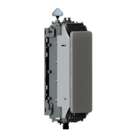
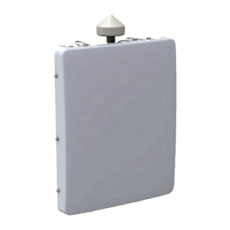
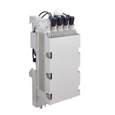
Airspan AirSynergy3 User manual

SYN-UG-018 Revision A0 (draft ver. c)
AirSynergy3
Equipment
InstallationGuide

AirSynergy3 Equipment Installation Guide
Page 2 | Commercial in Confidence SYN-UG-018
Copyright
© Copyright by Airspan Networks Inc., 2013. All rights reserved worldwide.
The information contained within this document is proprietary and is subject to all relevant copyright,
patent and other laws protecting intellectual property, as well as any specific agreements protecting
Airspan Networks Inc. rights in the aforesaid information. Neither this document nor the information
contained herein may be published, reproduced or disclosed to third parties, in whole or in part,
without the express, prior, written permission of Airspan Networks Inc. In addition, any use of this
document or the information contained herein for the purposes other than those for which it is
disclosed is strictly forbidden.
Airspan Networks Inc. reserves the right, without prior notice or liability, to make changes in
equipment design or specifications.
Information supplied by Airspan Networks Inc. is believed to be accurate and reliable. However, no
responsibility is assumed by Airspan Networks Inc. for the use thereof nor for the rights of third parties
which may be effected in any way by the use of thereof.
Any representation(s) in this document concerning performance of Airspan Networks Inc. product(s)
are for informational purposes only and are not warranties of future performance, either expressed or
implied. Airspan Networks Inc. standard limited warranty, stated in its sales contract or order
confirmation form, is the only warranty offered by Airspan Networks Inc. in relation thereto.
This document may contain flaws, omissions or typesetting errors; no warranty is granted nor liability
assumed in relation thereto unless specifically undertaken in Airspan Networks Inc. sales contract or
order confirmation. Information contained herein is periodically updated and changes will be
incorporated into subsequent editions. If you have encountered an error, please notify Airspan
Networks Inc. All specifications are subject to change without prior notice.
Product performance figures quoted within this document are indicative and for information purposes
only.
UK WEE Registration number: WEE/AB0207WZ

AirSynergy3 Equipment Installation Guide
Page 3 | Commercial in Confidence SYN-UG-018
Table of Contents
Copyright ...............................................................................................................................................2
Table of Contents..................................................................................................................................3
Summary of Figures .....................................................................................................................5
Summary of Tables.......................................................................................................................8
1About this Guide ...........................................................................................................................9
1.1 Purpose..................................................................................................................................9
1.2 Intended Audience................................................................................................................9
1.3 Conventions...........................................................................................................................9
1.4 Referenced Documentation ...............................................................................................10
1.5 Organisation of this Guide.................................................................................................10
2Introduction .................................................................................................................................11
2.1 General Overview for use with External Antenna............................................................11
2.1.1 Front Mounted Sector Antenna Arrangement..........................................................11
2.1.2 Switched Beam Antenna Arrangement.....................................................................12
2.1.3 Dual radio unit arrangement ......................................................................................12
2.2 Workflow of Installation......................................................................................................13
2.3 Installation Checklist ..........................................................................................................13
2.4 Verify Site Requirements....................................................................................................14
2.5 Verify Safety Requirements ...............................................................................................14
2.5.1 Warning of Hazardous Voltages................................................................................14
2.5.2 Adhere to European Directive 1999/519/EC .............................................................14
2.6 Verify Installation Requirements.......................................................................................15
2.6.1 Verify the Tools ...........................................................................................................15
2.6.2 Verify the Parts and Kits.............................................................................................16
2.6.3 Verify Components .....................................................................................................19
3Installing AirSynergy ..................................................................................................................22
3.1 Mount the AirSynergy Universal Mounting Plate.............................................................22
3.2 Fit Front Sector Antenna to AirSynergy ...........................................................................24

AirSynergy3 Equipment Installation Guide
Page 4 | Commercial in Confidence SYN-UG-018
3.3 Fit GPS Antenna to AirSynergy.........................................................................................25
3.4 Secure AirSynergy and Antenna to pole mount plate.....................................................26
4Connect and Manage cables......................................................................................................29
4.1 Fitting the Protection earth cable......................................................................................29
4.2 Connecting RF Jumper cables to External Antenna .......................................................31
4.3 Connect Power drop cable to the AirSynergy..................................................................32
5Power System Connection.........................................................................................................33
5.1 Run cables from the PSU to the AirSynergy....................................................................33
5.2 Wiring of the Drop cable to the power supply unit..........................................................35
5.3 Connecting the PSU to Mains............................................................................................39
6Automatic Discovery via Netspan .................................................................................................44
7Appendix A ..................................................................................................................................47
7.1 Review Job Sheet................................................................................................................47
8Appendix C –Glossary of Terms .............................................................................................54
9Appendix D –Checklist ..............................................................................................................55
10 Appendix E –PSU for USA.....................................................................................................56
11 Appendix F –FCC Requirements..........................................................................................58
12 Appendix G –Declaration of Conformance (CE) for Airsynergy .......................................62
13 Appendix H - Document Status .............................................................................................64
13.1 Revision History..................................................................................................................64

AirSynergy3 Equipment Installation Guide
Page 5 | Commercial in Confidence SYN-UG-018
Summary of Figures
Figure 1 –Typical AirSynergy with sun shield ...............................................................................11
Figure 2 –AirSynergy with front sector antenna fitted...................................................................11
Figure 3–AirSynergy with Switched Beam Antenna ......................................................................12
Figure 4 –AirSynergy dual radio configuration...............................................................................12
Figure 5 –Workflow of AirSynergy Installation..............................................................................13
Figure 6 –AirSynergy unit in typical packing box as supplied with foam inserts.......................19
Figure 7 –Single radio AirSynergy unit (connectorised) ..............................................................19
Figure 8 –Dual Radio Synergy (Can be any combination of 2 x connectorised or 1 x
connectorised and 1 with SBA).........................................................................................................19
Figure 9 –Single radio AirSynergy unit with Switched Beam Antenna (factory fitted)...............19
Figure 10 –Universal Mounting Plate and pole straps ..................................................................20
Figure 11 –Sun Shield with fixings...................................................................................................20
Figure 12 –Sector Antenna Mounting plate and fixings.................................................................20
Figure 13 –Sector Antenna (Check frequency variants)................................................................20
Figure 14 –PSU...................................................................................................................................21
Figure 15 –Enclosed PSU (US requirement) ...................................................................................21
Figure 16 –GPS antenna....................................................................................................................21
Figure 17 –GPS antenna mounting kit.............................................................................................21
Figure 18 –AirSynergy mounting plate and fixings......................................................................22
Figure 19 –Feed clamp bands through the quick release locking mechanisms........................22
Figure 20 –Press down the locking mechanism with the slack band fed through .....................23
Figure 21 –Tighten clamps with large flat blade screwdriver........................................................23
Figure 22 –AirSynergy mounting plate installed (large diameter concrete pole)........................23
Figure 23 –Fixing the front mount antenna to the mounting plate...............................................24
Figure 24 –Fitting the Front mount antenna assembly to AirSynergy ..........................................24
Figure 25 –Fitting the GPS antenna to the mounting bracket........................................................25
Figure 26 –GPS antenna cable connected .......................................................................................25
Figure 27 –Assembling the GPS antenna and bracket assembly to AirSynergy ........................26
Figure 28 –Lift AirSynergy to top of pole-mount plate..................................................................26

AirSynergy3 Equipment Installation Guide
Page 6 | Commercial in Confidence SYN-UG-018
Figure 29 –AirSynergy drops down into slots at the top of pole-mount plate ..........................27
Figure 30 –Gently lift the AirSynergy body until the bottom studs engage in the bottom slots
..............................................................................................................................................................27
Figure 31 –AirSynergy body engaged in the bottom slots............................................................27
Figure 32 –AirSynergy downtilt adjustment....................................................................................28
Figure 33 –Tighten flange nuts (4 positions) once the required mounting angle is set.............28
Figure 34–AirSynergy attachment of earthing cable.....................................................................29
Figure 35–Attach earth cable to pole...............................................................................................29
Figure 36 –Connecting the antenna RF cables..............................................................................31
Figure 37 –AirSynergy Front mount antenna connections –applying self -amalgamating tape
..............................................................................................................................................................31
Figure 38 –AirSynergy antenna connections –applying PVC tape.............................................32
Figure 39 –Attach the power cable to the AirSynergy ...................................................................32
Figure 40 –Tools required to connect the PSU...............................................................................33
Figure 41 –AirSynergy3 power and network cable overview diagram........................................34
Figure 42 –Preparing the end of the drop cable .............................................................................35
Figure 43 –Water proof power connector with the 2 halves separated........................................35
Figure 44 –Waterproof connector dis-assembled ready for installation on the cables .............35
Figure 45 –Cable gland and connector body positioned on the drop cable................................36
Figure 46 –Fit the cable ends into the connector and secure.......................................................36
Figure 47 –Male part of connector with both drop cable wires fitted...........................................36
Figure 48 –Connector contact position markings..........................................................................37
Figure 49 –Assemble the connector and tighten the gland...........................................................37
Figure 50 –Prepare the ends of the PSU cable and thread the connector part over the cable..37
Figure 51 –Female part of connector with both PSU cable wires fitted.......................................38
Figure 52 –Assemble the connector ad tighten the sealing gland ..............................................38
Figure 53 –Connector parts joined together ..................................................................................38
Figure 54 - High power (240W) PSU showing the Mains and low voltage connections..............39
Figure 55 –Standard power (100W) PSU..........................................................................................39
Figure 56 –Fix the PSU into position using self tapping screws .................................................39

AirSynergy3 Equipment Installation Guide
Page 7 | Commercial in Confidence SYN-UG-018
Figure 57- BS Config...........................................................................................................................41
Figure 56- Mgmt IP Config..................................................................................................................42
Figure 59- Reboot Confirmation........................................................................................................43
Figure 58- Discovery Tasks ...............................................................................................................44
Figure 61- Edit Discovery tasks parameters ....................................................................................45
Figure 62 - Discovery Target..............................................................................................................45
Figure 63 - Discovery Test .................................................................................................................46
Figure 62 - Removing the existing stud mounting plates...............................................................49
Figure 63 - Fitting the stud joining plates.........................................................................................49
Figure 64 - Position back to back assembly on side to tighten all joining plate screws ...........50
Figure 65 - Mounting method with pole clamps recommended for back to back installations..50
Figure 68 - Flatten straps against the mounting plate for back to back installations ................51
Figure 69 - Back to Back AirSynergy mounted on pole with 4 mounting straps .........................52
Figure 70 –M6 Screw fixing point as safety line anchor point ......................................................53
Figure 69 –AirSynergy Mains PSU and enclosure for USA deployments....................................56
Figure 71 –Internal PSU and and cable terminations.....................................................................56

AirSynergy3 Equipment Installation Guide
Page 8 | Commercial in Confidence SYN-UG-018
Summary of Tables
Table 1 –AirSynergy3 installation tools..........................................................................................15
Table 2 –AirSynergy3 installation parts and kits...........................................................................16
Table 3 –External Antenna and feeder kits (OPTION) ...................................................................18
Table 4 - AirSynergy additional (consumable) items ....................................................................18

AirSynergy3 Equipment Installation Guide
Page 9 | Commercial in Confidence SYN-UG-018
1 About this Guide
This section discusses the purpose, intended audience, conventions, referenced documentation and
organisation for this guide.
1.1 Purpose
This guide provides the workflow and step-by-step procedures for Installation of the AirSynergy
equipment. These procedures include:
Verify Prerequisites
Install the AirSynergy3 Radio equipment
Install the PSU equipment
Connect and manage cables
Commission and discover via Netspan, to be ready for full configuration
1.2 Intended Audience
This guide is intended for persons who are responsible for installing AirSynergy equipment. These
persons should have a working knowledge of the equipment.
1.3 Conventions
This document uses the following informational conventions.
Icon
Description
Checkpoint: Marks a point in the workflow where there may be an exit or branch
to some other procedure. At each Checkpoint the reason for an exit or branch is
given along with specific directions to locate the entry point in the other
procedure.
Reference: Gives a resource in the workflow that may be needed to complete a
procedure along with specific directions to use the resource.
Caution: Describes a possible risk and how to lessen or avoid the risk.
Advice: Provides a recommendation based on best practice.
Note: Provides useful information.

AirSynergy3 Equipment Installation Guide
Page 10 | Commercial in Confidence SYN-UG-018
1.4 Referenced Documentation
Place holder for Product Bulletins and other related documents
1.5 Organisation of this Guide
This guide is organised into the following Sections:
About this Guide
Introduction
Get Started
Verify Prerequisites
Install the AirSynergy Radio equipment
Install the PSU equipment
Connect and manage cables
Set BS Management IP & BSID via Web Page
Connect and manage cables
Appendixes

AirSynergy3 Equipment Installation Guide
Page 11 | Commercial in Confidence SYN-UG-018
2 Introduction
This section provides a descriptive overview of the product.
2.1 General Overview for use with External Antenna
AirSynergy equipment comes in a range of frequency variants that can be mounted with different
antenna options and formats.
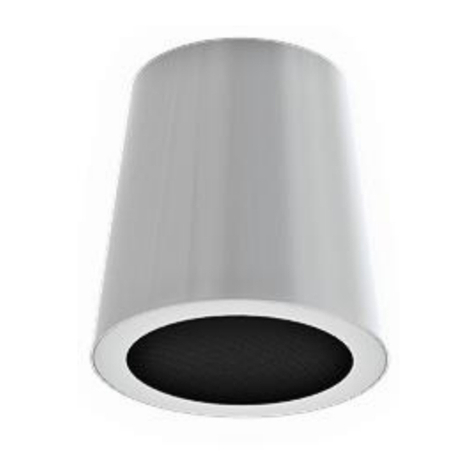
Figure 1 –Typical AirSynergy with sun shield
2.1.1 Front Mounted Sector Antenna Arrangement
A typical sector installation will have a cross-polar sector antenna fitted directly to the front of the
AirSynergy main unit. (This is fitted instead of the sun-shield).
Figure 2 –AirSynergy with front sector antenna fitted

AirSynergy3 Equipment Installation Guide
Page 12 | Commercial in Confidence SYN-UG-018
2.1.2 Switched Beam Antenna Arrangement
A switched beam antenna version (factory built option) with built in GPS antenna allows for flexible
iBridge backhaul functionality where the strongest signal from any direction is automatically selected.
The same antenna can also be configured in omni mode for the support of access.
Figure 3–AirSynergy with Switched Beam Antenna
2.1.3 Dual radio unit arrangement
AirSynergy units may also be supplied in a dual radio arrangement. Note: Various antenna options
can be selected for each AirSynergy to perform the required combination of backhaul and access
functionality. An extended sun-shield is also available for this format.
Figure 4 –AirSynergy dual radio configuration

AirSynergy3 Equipment Installation Guide
Page 13 | Commercial in Confidence SYN-UG-018
Getting Started
2.2 Workflow of Installation
The workflow required to install the AirSynergy equipment is shown in the following diagram:
Figure 5 –Workflow of AirSynergy Installation
2.3 Installation Checklist
Plan the installation of the AirSynergy Unit by using the Installation Checklist in Appendix A

AirSynergy3 Equipment Installation Guide
Page 14 | Commercial in Confidence SYN-UG-018
2.4 Verify Site Requirements
To set up the AirSynergy a connection to a Netspan server PC will be required.
2.5 Verify Safety Requirements
Read and follow all warning notices and instructions marked on the product or included in this
manual.
When installed in the final configuration, the product must comply with the applicable Safety
Standards and regulatory requirements of the country in which it is installed. If necessary, consult with
the appropriate regulatory agencies and inspection authorities to ensure compliance.
Ascertain the radiation hazards when working in an environment close to other antennas and
Electromagnetic fields, e.g. working on towers with other microwave transmitters etc. and act
accordingly.
2.5.1 Warning of Hazardous Voltages
On AC installations, hazardous voltages exist. Use caution when verifying or working with AC power.
Remove metal jewellery that could come into contact with AC power.
On DC sections, short circuiting the low voltage, low impedance circuits can cause arcing that may
result in burns or eye damage. Remove rings, watches etc. to avoid shorting DC circuits.
Note: Airspan products do not contain hazardous substances (as defined in UK
Control of Substances Hazardous to Health Regulations 1989 and the Dangerous
Substances Regulations 1990). At the end of any Airspan products life cycle, the
customer should consult with Airspan to ensure that the product is disposed of in
conformance with the relevant regulatory requirements.
Caution: Any modifications to this device not expressly authorised by the
manufacturer could void the users’ authority to operate this device.
2.5.2 Adhere to European Directive 1999/519/EC
European Council Recommendation1999/519/EC details basic restrictions and reference levels on
human exposure to electromagnetic fields as advised by the ICNIRP. Adherence to these
recommended restrictions and reference levels should provide a high level of protection as regards
the established health effects that may result from exposure to electromagnetic fields.

AirSynergy3 Equipment Installation Guide
Page 15 | Commercial in Confidence SYN-UG-018
2.6 Verify Installation Requirements
2.6.1 Verify the Tools
Table 1 –AirSynergy3 installation tools
Tools
Small flat blade Screwdriver
(For screw terminals inside power cable joiner)
Large Flat Bladed Screwdriver
(Securing of the pole straps)
Medium Cross-head Screwdriver
(Power supply covers/mounting screws mounting screws)
13mm wrench x 2
(Heavy-duty pole clamp option only)
10mm wrench
(AirSynergy securing flange nuts)
Large pliers
(Tightening cable glands on the US PSU - To fit 15mm across flats)
Knife (for stripping back insulation)
Wire cutters
Wire strippers
(Cutting insulation)
Ring terminals crimp tool
Tilt-meter
(If accurate downtilt of antenna needs to be set)

AirSynergy3 Equipment Installation Guide
Page 16 | Commercial in Confidence SYN-UG-018
2.6.2 Verify the Parts and Kits
Table 2 –AirSynergy3 installation parts and kits
Installation Kit /
Part:
Installation Kit details
Note:
Main AirSynergy
parts
1 x AirSynergy Universal
Mounting Plate and pole strap
kit
(Includes 2 pole straps for poles
up to 200mm diameter)
AirSynergy unit(s)
Frequency band specific and
available with and without
integral switched beam antenna.
Check against order and
requirement to ensure the
correct unit type to be installed
Either of the following:
1 x Sun Shield (for single unit
installation where a separately
mounted external antenna is
deployed)
Sun shield
6 Countersunk head fixing
screws
OR (for front mount antenna
option)
1 x Sector Antenna mounting
plate with fixing kit
4 M4 nuts
4 M4 flat washers
4 M4 spring washers
4 Cable ties
4 M5 SEM
1 x Sector Antenna (front
mounting)
Additionally required for any
non-switched beam antenna
versions of AirSynergy
GPS Antenna
GPS Antenna mounting kit
Bracket
M6 screw
M6 plain washer
M6 spring washer
TNC to TNC cable (25cm)

AirSynergy3 Equipment Installation Guide
Page 17 | Commercial in Confidence SYN-UG-018
Additionally required for back to
back unit installations.
Note: Dual radio Synergy3 units
in most cases pre-assembled
from the factory
1 x back to back joining kit
4 joining straps with mounting
studs and flange nuts pre-fitted.
16 M5 countersink screws
1 x Extended sun shield ( If no
front mount antenna is to be
fitted to the front face of the
back to back AirSynergy units)
OPTIONAL Heavy-
duty mounting (for
specific mounting
locations)
1 heavy-duty pole clamp
mounting kit
4 clamps
4 M8x150 bolts
4 M8 plain washer
4 M8 spring washer
Connecting cables
CAT5e
External grade 30m with
Synergy3 compatible RJ45
connector weather hood pre-
fitted. One for each AirSynergy
unit unless iBridge backhaul
invoked
Earthing cable
M6 Lug at each end ( for the
Power Supply and
power cable
48V PSU module
1 per AirSynergy unit (or dual
radio unit)
Power drop cable
1 per AirSynergy unit (or dual
radio unit) with external grade
30m power cable with Synergy3
compatible power connector
weather hood pre-fitted.
Cable join kit
1 per AirSynergy unit (or dual
radio unit)
48V PSU in weatherproof
enclosure (NEMA approved)
Alternative to the standard 48V
PSU and is required for all North
American installations

AirSynergy3 Equipment Installation Guide
Page 18 | Commercial in Confidence SYN-UG-018
Table 3 –External Antenna and feeder kits (OPTION)
Installation Kit / Part
Note
External Antenna
Many variants - Check against
order and requirement to ensure
the correct type is installed
Typically a 2 port cross-polar antenna
Pole mounting kits (supplied with antenna)
Short Feeder cable
0.5M feeder tails x 2 (Suitable for mounting
antenna directly above the AirSynergy unit)
Long Feeder tail
1.5M feeder tails x2 (Suitable for mounting
antenna on the same pole immediately behind the
AirSynergy unit or where the Antenna needs to be
spaced away from the AirSynergy unit)
Table 4 - AirSynergy additional (consumable) items
Additional items (not provided by Airspan)
Cable ties
Self-amalgamating tape
Black PVC tape
Ring terminals for earth strap, M6
Earth strap cable (4mm), yellow and green cable

AirSynergy3 Equipment Installation Guide
Page 19 | Commercial in Confidence SYN-UG-018
2.6.3 Verify Components
The following figures show and describe the AirSynergy components and accessory kits
Figure 6 –AirSynergy unit in typical packing box as supplied with foam inserts
Figure 7 –Single radio AirSynergy unit (connectorised)
Figure 8 –Dual Radio Synergy (Can be any combination of 2 x connectorised or 1 x connectorised
and 1 with SBA)
Figure 9 –Single radio AirSynergy unit with Switched Beam Antenna (factory fitted)

AirSynergy3 Equipment Installation Guide
Page 20 | Commercial in Confidence SYN-UG-018
Figure 10 –Universal Mounting Plate and pole straps
Figure 11 –Sun Shield with fixings
Figure 12 –Sector Antenna Mounting plate and fixings
Figure 13 –Sector Antenna (Check frequency variants)
This manual suits for next models
1
Table of contents
Other Airspan Network Hardware manuals

Airspan
Airspan AS3010 Manual

Airspan
Airspan AIRSTAR 1900 User manual

Airspan
Airspan AirSpeed-1200 eNB Operating and maintenance instructions

Airspan
Airspan AirHarmony-1000 User manual

Airspan
Airspan Sprint Magic Box User manual

Airspan
Airspan AirHarmony-4000 User manual

Airspan
Airspan AirSpeed 1050 B3 User manual

Airspan
Airspan AirSpeed 1030 B48 User manual

Airspan
Airspan AS4000 Guide

Airspan
Airspan AirSpeed 1000A User manual