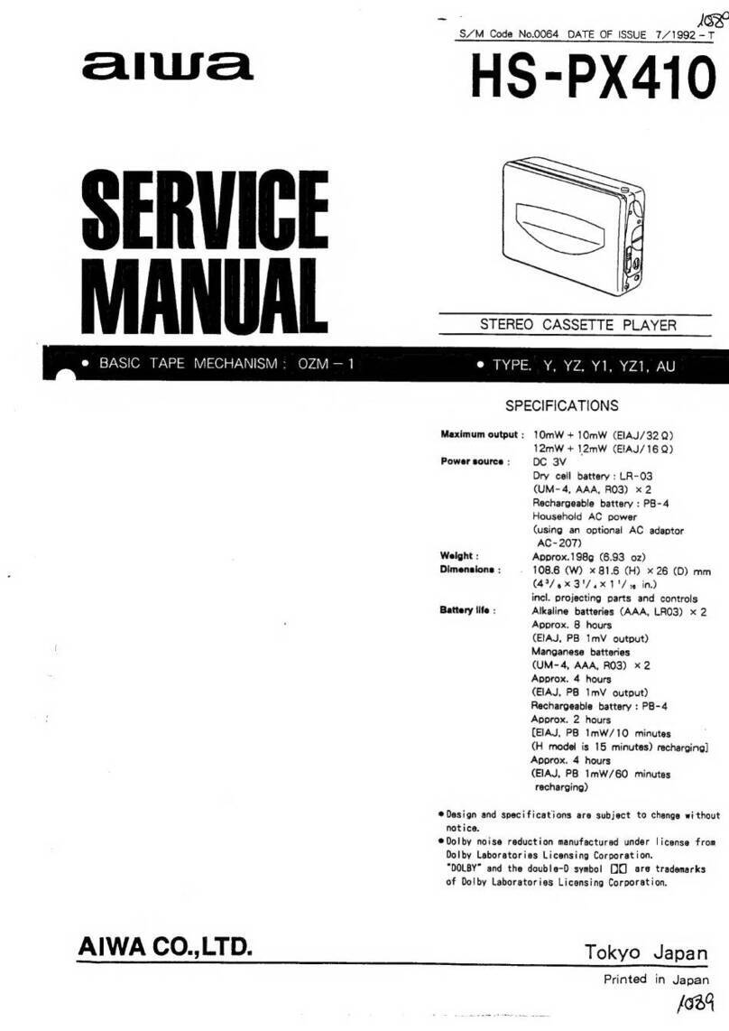
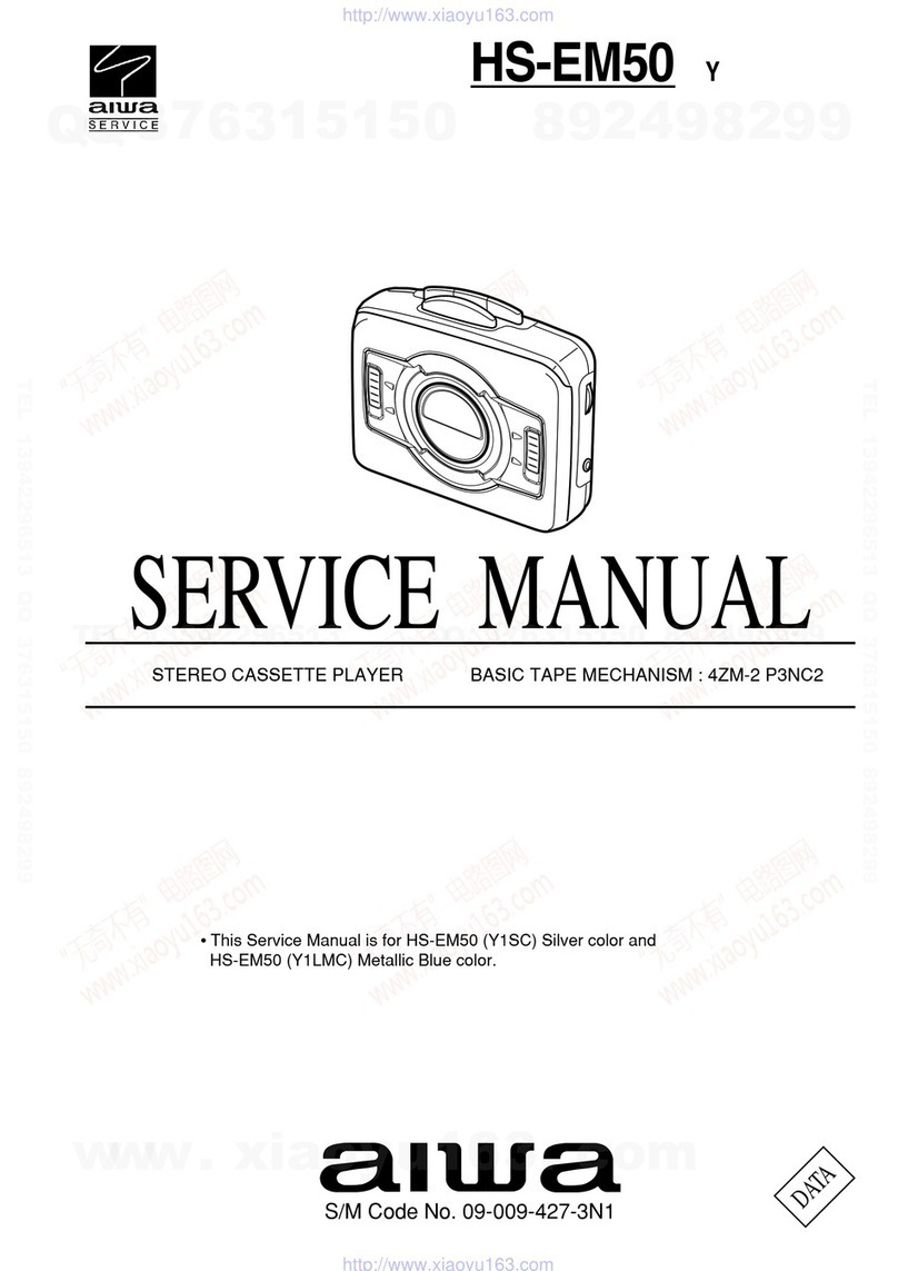
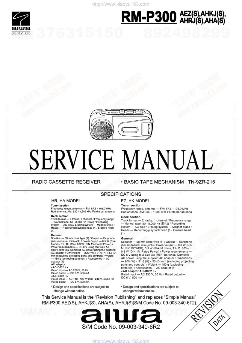
Aiwa HS-TX394 User manual

SERVICE MANUAL
HS-TX394
HS-TX396
HS-TX399
YU,YL,YZ
YH,YL,YZ,YJ
YL
STEREO RADIO
CASSETTE PLAYER BASIC TAPE MECHANISM : 4ZM-2
(P5NC,P5NF)
S/M Code No. 09-991-404-8R1
REVISION
All manuals and user guides at all-guides.com
all-guides.com

Design and specifications are subject to change without
notice.
SPECIFICATIONS
Frequency range: For using in North and South America
AM: 530 1,710 kHz (10 kHz step)
FM1,FM2: 87.5 108.1 MHz (200 kHz step)
For using in Europe and other countries
AM: 531 1,602 kHz (9 kHz step)
FM1,FM2: 87.5 108 MHz (50 kHz step)
For using in Japan <YU,YL>
AM: 531 1,629 kHz (9 kHz step)
FM1,FM2: 76 108 MHz
(100 kHz step in 76 90 MHz, 50 kHz step in 90 108 MHz)
Maximum output: 4 mW + 4 mW (EIAJ/32Ω)<YZ>
15 mW + 15 mW (EIAJ/32Ω)<YU,YL,YH>
Power source: DC 3V using two R6 (size AA) dry cell batteries
AC house current using an optional AC adaptor
AIWA AC D302 <YH>
Battery life (EIAJ 1 mW output):
Approx. 7 hours using R6P (size AA) manganese batteries
Approx. 22 hours using LR6 (size AA) alkaline batteries
Maximum dimensions: 116.7 (W) x 91.5 (H) x 35 (D) mm (45/8 x 33/4 x 15/8 in.)
Weight Approx.140g (4.9 oz) (excluding batteries)
DESCRIPTIONREF.NO. KANRI
NO.
ACCESSORIES / PACKAGE LIST
PARTNO.
1 8Z-HRC-904-010 IB,Y(DGI)-INTX396<396YZ>
1 8Z-HRC-911-010 IB,Y(DGI)-INTX394<394YZ>
1 8Z-HRC-903-010 IB,Y(ESF)-TX396 IN<396YZ>
1 8Z-HRC-910-010 IB,Y(ESF)-INTX394<394YZ>
1 8Z-HRC-907-010 IB,Y(POHCZ)-INTX396<396YZ>
1 8Z-HRC-912-010 IB,Y(POHCZ)-INTX394<394YZ>
1 8Z-HRC-918-010 IB,YJ(ECC)-TX396 IN<YJ>
1 8Z-HRC-919-010 IB,YH(ECC)-TX396C<YH>
1 8Z-HRC-921-010 IB,YL-TX399-CCE<399YL>
1 8Z-HRC-920-010 IB,YL(ESP)-TX394 IN<394YL>
1 8Z-HRC-906-010 IB,YL(ESP)-TX396C<[S]396YL>
1 8Z-HRC-909-010 IB,YL(ESP)-IN<[S]396YL1,[S]396YLB>
1 8Z-HRC-908-010 IB,YU(ESF)-IN<YU>
2 84-447-019-310 CLIP,BELT
3 87-B30-150-110 HEADPHONE,HP-M006A(F)<YH,YZ>
3 87-B30-124-110 HEADPHONE,HP-M028<YU,[S]396YLB,[S]396YL>
3 87-B30-145-110 HEADPHONE,HP-M029(T)<394YL,[S]396YL1,399YL>
2SA1362
2SC2714
2SC2712
KTA1298Y
BE
C
RN2411
RN2407
RN1411
RN1407
DTC144EK
TRANSISTOR ILLUSTRATION
2
All manuals and user guides at all-guides.com

DESCRIPTIONREF. NO. KANRI
NO.
PARTNO. KANRI
NO.
REF. NO. DESCRIPTIONPARTNO.
ELECTRICAL MAIN PARTS LIST
IC
87-A21-235-080 C-IC,LAG668FTF
87-A20-851-040 C-IC,TA2111F
87-A21-049-010 C-IC,LC72343G-9482<YH,YJ,YZ>
87-A21-149-010 C-IC,TC9322FB-501<YU,YL>
87-001-145-080 IC,TA8126F
TRANSISTOR
89-113-625-080 TR,2SA1362GR(120MHZ,0.
87-026-210-080 CHIP-TR,DTC144EK
87-026-264-080 C-TR,RN1411
87-026-262-080 C-TR,RN1407
89-327-143-080 TR,2SC2714 (0.1W)
87-026-268-080 C-TR,RN2411
87-A30-159-080 C-TR,KTA1298Y
89-327-125-080 CHIP TR,2SC2712GR
DIODE
87-001-142-080 DIODE,1SS294 (100MA)
87-020-027-080 CHIP-DIODE 1SS184
87-A40-260-080 C-ZENER,UDZ2.0B<YH,YJ,YZ>
87-026-267-080 LIGHT EMITTING DIODE,RN2407
MAIN C.B
BPF101 87-A90-601-010 FLTR,BPF GFWB7
C1 87-010-179-080 CAP,CHIP S B1200P
C2 87-010-179-080 CAP,CHIP S B1200P
C3 87-010-501-040 E/CAP GAS 47-4
C4 87-010-820-040 CAP,E 47-4 (MJ)
C5 87-016-369-080 C-CAP,S 0.033-25 KB GRM
C6 87-016-369-080 C-CAP,S 0.033-25 KB GRM
C7 87-012-141-080 CHIP-CAPACITOR,0.22-16F
C8 87-012-141-080 CHIP-CAPACITOR,0.22-16F
C9 87-010-196-080 CHIP CAPACITOR,0.1-25
C10 87-010-822-040 CAP,E 220-4 (MJ)
C11 87-010-822-040 CAP,E 220-4 (MJ)
C12 87-010-178-080 CHIP CAP 1000P
C13 87-A11-235-080 C-CAP,TN 3.3-4 M AM004R
C14 87-010-503-040 CAP,E 220-4 GAS
C15 87-A11-187-080 C-CAP,TN 10-4 M AM004R
C16 87-010-196-080 CHIP CAPACITOR,0.1-25
C17 82-HJ5-612-010 CAP,E 470-4
C18 87-010-177-080 C-CAP,S 820P-50 SL
C19 87-010-177-080 C-CAP,S 820P-50 SL
C20 87-010-178-080 CHIP CAP 1000P
C21 87-010-178-080 CHIP CAP 1000P
C22 87-A11-187-080 C-CAP,TN 10-4 M AM004R
C23 87-010-805-080 CAP, S 1-16
C24 87-A11-187-080 C-CAP,TN 10-4 M AM004R
C25 87-010-805-080 CAP, S 1-16
C101 87-010-194-080 CAP, CHIP 0.047
C102 87-010-197-080 CAP, CHIP 0.01 DM
C103 87-010-196-080 CHIP CAPACITOR,0.1-25
C104 87-010-320-080 C-CAP,S 68P-50 CH
C105 87-012-140-080 CAP 470P
C106 87-012-153-080 C-CAP,S 120P-50 CH
C107 87-010-145-080 C-CAP,S 1P-50 CH
C108 87-012-155-080 C-CAP 180P-50CH
C110 87-010-154-080 CAP CHIP 10P
C111 87-010-197-080 CAP, CHIP 0.01 DM<YZ>
C111 87-010-805-080 CAP,S 1-16<YU,YL,YH,YJ>
C112 87-010-312-080 C-CAP,S 15P-50 CH
C113 87-010-154-080 CAP CHIP 10P
C114 87-010-197-080 CAP, CHIP 0.01 DM
C115 87-010-146-080 C-CAP,S 2P-50 C CH<YU,YL>
C115 87-010-145-080 C-CAP,S 1P-50 CH<YL,YH,YJ,YZ>
C117 87-010-196-080 CHIP CAPACITOR,0.1-25
C118 87-010-805-080 CAP, S 1-16
C119 87-010-197-080 CAP, CHIP 0.01 DM
C120 87-010-194-080 C-CAP,S 0.047-25 ZF<YU,YL>
C120 87-010-197-080 CAP, CHIP 0.01 DM<YZ>
C121 87-012-157-080 C-CAP,S 330P-50 CH
C122 87-012-141-080 CHIP-CAPACITOR,0.22-16F
C123 87-012-141-080 CHIP-CAPACITOR,0.22-16F
C124 87-010-805-080 CAP, S 1-16
C125 87-010-196-080 CHIP CAPACITOR,0.1-25
C126 87-010-196-080 CHIP CAPACITOR,0.1-25
C127 87-010-419-040 CAP,E 4.7-16 5L
C128 87-010-452-080 CAPACITOR,1-16
C129 87-010-426-080 C-CAP,S 0.012-25 B
C130 87-010-426-080 C-CAP,S 0.012-25 B
C131 87-010-426-080 C-CAP,S 0.012-25 KB
C132 87-010-426-080 C-CAP,S 0.012-25 KB
C133 87-010-822-040 CAP,E 220-4 (MJ)
C134 87-010-822-040 CAP,E 220-4 (MJ)
C136 87-010-178-080 CHIP CAP 1000P
C138 87-016-461-080 C-CAP,S 0.47-16F
C140 87-010-178-080 C-CAP,S 1000P-50 KB<YH,YJ,YZ>
C140 87-012-154-080 C-CAP,S 150P-50 J CH<YU,YL>
C141 87-010-178-080 C-CAP,S 1000P-50 KB<YH,YJ,YZ>
C142 87-010-178-080 C-CAP,S 1000P-50 KB
C143 87-010-178-080 C-CAP,S 1000P-50 KB<YH,YJ,YZ>
C145 87-010-178-080 C-CAP,S 1000P-50 KB<YU,YL>
C146 87-010-197-080 C-CAP,S 0.01-25 KB<YU,YL>
C150 87-010-178-080 C-CAP,S 1000P-50 KB<YU,YL>
C150 87-010-321-080 C-CAP,S 82P-50 J CH<YU,YL>
C401 87-010-196-080 CHIP CAPACITOR,0.1-25
C402 87-010-196-080 CHIP CAPACITOR,0.1-25
C403 87-010-805-080 CAP, S 1-16
C404 87-010-805-080 CAP, S 1-16
C405 87-010-499-040 CAP,E 22-6.3 GAS
CF101 87-A91-162-010 FLTR,PFS450A7
CF104 87-A91-093-010 FLTR,KIT KSKM2CD-AO-003
D101 87-A40-462-040 C-VARI-CAP,SVC347(S)
D102 87-A40-484-070 C-VARI-CAP,SVC203CP
D103 87-A40-484-070 C-VARI-CAP,SVC203CP
J1 85-HRL-623-010 JACK,3.5 ST BLK
J2 87-A60-849-010 JACK,DC DIA 2.75 BLK<YH>
L1 87-A50-038-010 COIL,RF CHOKE
L101 8Z-HRC-605-010 BAR-ANT,MW
L102 8Z-HRC-607-010 COIL,FM RF
L103 8Z-HRC-606-010 COIL,OSC FM
L104 87-003-226-080 MICRO INDUCTOR 100UJ
L105 87-A91-063-010 IFT,AM 450KHZ
R9 87-A00-330-080 RES,M/F 220-1/8W 3900PPM
SFR1 87-A91-057-040 C-SFR,3.3K B RHO3AXAN4X
SW1 87-A90-133-010 SW LEAF LSA1120JAU
TH1 87-026-256-090 THERMISTOR, HT-100
VC101 87-011-217-010 TRIMER,10P VCT35
VR1 87-A90-981-010 VR,RTRY 20KBX1
FRONT C.B
C205 87-010-152-080 C-CAP,S 8P-50 CH<YH,YJ,YZ>
C206 87-010-152-080 C-CAP,S 8P-50 CH<YH,YJ,YZ>
C207 87-010-805-080 CAP, S 1-16<YH,YJ,YZ>
C209 87-010-197-080 CAP, CHIP 0.01 DM<YH,YJ,YZ>
C210 87-010-196-080 C-CAP,0.1-25<YH,YJ,YZ>
C211 87-012-141-080 C-CAP,0.22-16F<YH,YJ,YZ>
C212 87-010-196-080 C-CAP,0.1-25<YH,YJ,YZ>
C213 87-010-805-080 CAP, S 1-16<YH,YJ,YZ>
C214 87-010-178-080 CHIP CAP 1000P<YH,YJ,YZ>
C215 87-010-182-080 C-CAP,S 2200P-50 B<YH,YJ,YZ>
C216 87-010-805-080 CAP, S 1-16<YH,YJ,YZ>
C218 87-010-805-080 CAP, S 1-16<YH,YJ,YZ>
C251 87-010-180-080 C-CER 1500P
C252 87-010-805-080 CAP, S 1-16
3
All manuals and user guides at all-guides.com

DESCRIPTIONREF. NO. KANRI
NO.
PARTNO. KANRI
NO.
REF. NO. DESCRIPTIONPARTNO.
C253 87-010-197-080 CAP, CHIP 0.01 DM
C254 87-010-452-080 CAPACITOR,1-16
C255 87-010-197-080 CAP, CHIP 0.01 DM
C256 87-010-150-080 C-CAP,S 6P-50 CH
C257 87-012-156-080 C-CAP,S 220P-50 CH
C258 87-010-805-080 CAP, S 1-16
C271 87-010-181-080 CAP,CHIP S 1800P<YU,YL>
C272 87-010-181-080 CAP,CHIP S 1800P<YU,YL>
C273 87-010-181-080 CAP,CHIP S 1800P<YU,YL>
C274 87-010-181-080 CAP,CHIP S 1800P<YU,YL>
C275 87-010-805-080 CAP, S 1-16<YU,YL>
C277 87-010-805-080 CAP, S 1-16<YU,YL>
C278 87-010-805-080 CAP, S 1-16<YU,YL>
C279 87-010-805-080 CAP, S 1-16<YU,YL>
C280 87-010-312-080 C-CAP,S 15P-50 CH<YU,YL>
C281 87-010-312-080 C-CAP,S 15P-50 CH<YU,YL>
C282 87-012-142-080 CAP, S 0.33-16<YU,YL>
C284 87-010-196-080 CHIP CAPACITOR,0.1-25<YU,YL>
C285 87-010-196-080 CHIP CAPACITOR,0.1-25<YU,YL>
C287 87-010-196-080 CHIP CAPACITOR,0.1-25<YU,YL>
C288 87-010-427-080 C-CAP,S 0.039-25 B<YU,YL>
L251 87-A50-396-040 C-COIL,D-D CONV CP-4LBM
LCD201 8Z-HRC-603-010 LCD,ASSY(BAND/TU) 19P<YH,YJ,YZ>
LCD201 88-HRC-610-010 LCD,HS ASSY(BAND/TU)<YU,YL>
R216 87-022-375-080 C-RES,S 680K-1/10W F<YH,YJ,YZ>
R217 87-022-374-080 C-RES,S 560K-1/10WF<YH,YJ,YZ>
R275 87-022-359-080 C-RES,S22K-1/10WF<YU,YL>
R276 87-022-359-080 C-RES,S22K-1/10WF<YU,YL>
R277 87-022-361-080 C-RES,S 47K-1/10W F<YU,YL>
SW213 87-036-304-080 C-SW,SL 1-1-2
TH201 87-A90-547-080 C-THMS,47K (5%)NTH 5G<YU,YL>
X201 87-A70-082-010 VIB,XTAL 75KHZ<YH>
X201 87-A70-173-010 VIB,XTAL 75KHZ DT-261<EXCEPT YH>
FLEX C.B
8Z-HRC-604-010 FF-CABLE, 17P
4
All manuals and user guides at all-guides.com

LCD DIAGRAM
5 6
88
1608
2125
3216
1.6 0.8 0.45
2 1.25 0.45
3.2 1.6
108
118
128
:A
:A
0.55
Resistor
Dimensions
CHIP RESISTOR PART CODE
Chip Resistor Part Coding
A
Resistor Code Figure
Value of resistor
Chip resistor
Wattage
1/16W
1/10W
1/8W
Type Tolerance
5%
5%
5%
Symbol
CJ
CJ
CJ
Form
Lt
W
L
W
t
LCD, HS ASSY (BAND/TU) <YU, YL>
GRIDASSIGNMENT
LCD, HS ASSY (BAND/TU) <YH, YJ, YZ>
GRIDASSIGNMENT
ANODECONNECTION
ANODECONNECTION
All manuals and user guides at all-guides.com

WIRING - 1 (MAIN)
7 8
27 26 25 24 23 22 21 20 19 18 17 16 15 14 13 12 11 10 9 8 7 6 5 4 3 2 1
A
B
C
D
E
F
G
H
I
J
K
L
M
N
O
P
Q
R
All manuals and user guides at all-guides.com
all-guides.com

WIRING - 1 (MAIN)
910
1 2 3 4 5 6 7 8 9 10 11 12 13 14 15 16 17 18 19 20 21 22 23 24 25 26 27
A
B
C
D
E
F
G
H
I
J
K
L
M
N
O
P
Q
R
All manuals and user guides at all-guides.com

WIRING - 2 (FRONT: 1/2) <YU,YL>
1211
27 26 25 24 23 22 21 20 19 18 17 16 15 14 13 12 11 10 9 8 7 6 5 4 3 2 1
A
B
C
D
E
F
G
H
I
J
K
L
M
N
O
P
Q
R
All manuals and user guides at all-guides.com

1413
WIRING - 2 (FRONT: 1/2) <YU,YL>
1 2 3 4 5 6 7 8 9 10 11 12 13 14 15 16 17 18 19 20 21 22 23 24 25 26 27
A
B
C
D
E
F
G
H
I
J
K
L
M
N
O
P
Q
R
All manuals and user guides at all-guides.com

WIRING - 3 (FRONT: 2/2) <YH,YZ,YJ>
1615
27 26 25 24 23 22 21 20 19 18 17 16 15 14 13 12 11 10 9 8 7 6 5 4 3 2 1
A
B
C
D
E
F
G
H
I
J
K
L
M
N
O
P
Q
R
All manuals and user guides at all-guides.com

WIRING - 3 (FRONT: 2/2) <YH,YZ,YJ>
1 2 3 4 5 6 7 8 9 10 11 12 13 14 15 16 17 18 19 20 21 22 23 24 25 26 27
A
B
C
D
E
F
G
H
I
J
K
L
M
N
O
P
Q
R
1817
All manuals and user guides at all-guides.com
all-guides.com

SCHEMATIC DIAGRAM - 1 (MAIN)
2019
All manuals and user guides at all-guides.com

SCHEMATIC DIAGRAM - 2 (FRONT: YU,YL)
2221
X201:75kHZ
All manuals and user guides at all-guides.com

SCHEMATIC DIAGRAM - 3 (FRONT: YH,YZ,YJ)
2423
All manuals and user guides at all-guides.com

25 26
IC BLOCK DIAGRAM
ICDESCRIPTION
PinNo. PinName I/O Description
1 COM 1 O LCD commn output 1.
2 COM 2 O LCD commn output 2.
3 COM 3 O LCD commn output 3.
4 S1 O LCD segment output.
5 S2 O LCD segment output.
6 S3 O LCD segment output.
7 S4 O LCD segment output.
8 S5 O LCD segment output.
9 S6 O LCD segment output.
10 S7 O LCD segment output.
11 S8 O LCD segment output.
12 S9 O LCD segment output.
13 S10 O LCD segment output.
14 S11 O LCD segment output.
15 S12 O LCD segment output.
16 S13 O LCD segment output.
17 S14 O LCD segment output.
18 S15 O LCD segment output.
19 S16 O LCD segment output.
20 S17 O LCD segment output.
21 S18 O LCD segment output.
22 S19 O LCD segment output.
23 S20 (NC) O LCD segment output. (Not connected)
24 S21 (NC) O LCD segment output. (Not connected)
IC,TC9322FB-501
PinNo. PinName I/O Description
25 S22 (NC) O LCD segment output. (Not connected)
26 S23 (NC) O LCD segment output. (Not connected)
27 K0 I Key matrix input.
28 K1 I Key matrix input.
29 K2 I Key matrix input.
30 K3 I Key matrix input.
31 T0 O Key return timing output.
32 T1 O Key return timing output.
33 T2 O Key return timing output.
34 T3 O Key return timing output.
35 FM / AM O 'H' : FM out, 'L' : AM out.
36 FM MN / ST O 'H' : FM Stereo out, 'L' : FM Mono out.
37 S-BASS O S-BASS switching output. 'H': OFF, 'L' :ON.
38 ROCK - Not connected.
39 DES I These two input ports determine the destination.
40 DES I
In Clock mode: 'H' = LCD display TAPE. 'L' : = LCD display TIME.
41 TAPE / ST I In FM Stereo mode : 'H' = FM ST indicator will Flash.
'L' = FM ST indicator no Flash.
42 POWER CHECK I A / D in for power supply voltage level.
43 REMOTE I A / D in for remote controller.
44 POWER SW O 'H' : Power Off, 'L' : Power On.
45 HOLD I 'H' : Hold Off, 'L' :Hold On.
46 BUZZER O Buzzer output.
47 MUTE O Mute output..
48 TEST - Connected to ground.
49 WAKE UP I Wake up the system from Memory back-up mode.
50 TUNE IN I 'L' : LCD display 'TUNED'.
51 TU OUT O When tuner on, 'L' level is output.
52 PLL OUT O Phase comparison output.
53 GND - Ground terminal.
54 FMIN I FM oscillator signal input.
55 AMIN I AM oscillator signal input.
56 VDD - Supply voltage terminal.
57 RESET I System reset input.
58 XOUT - Crystaloscillatorpin.
59 XIN - Crystaloscillatorpin.
60 VXT - Power supply for crystal oscillator.
61 VLCD - Referencevoltage for LCDdriver.
62 C1 - Voltagedoublerboosting.
63 C2 -
64 VEE - Connected to ground.
IC,LAG668FTF
All manuals and user guides at all-guides.com

1 XOUT - Crystal oscillator pin.
2 TEST2 - Connected to ground.
3 PA3 I Key matrix input.
4 PA2 I Key matrix input.
5 PA1 I Key matrix input.
6 PA0 I Key matrix input.
7 PB3 O Key return timing output.
8 PB2 O Key return timing output.
9 PB1 O Key return timing output.
10 PB0 O Key return timing output.
11 FM / AM O 'H' : FM out, 'L' : AM out.
12 FM ST / MN O 'H' : FM Stereo out, 'L' : FM Mono out.
3
13 S-BASS O S-BASS switching output. 'H' : OFF, 'L': ON.
14 NC - Not connected.
15 DES I These two input ports determine the destination.
16 DES I
In Clock mode: 'H' = LCD display TAPE. 'L' = LCD display TIME.
17 TAPE / ST I In FM Stereo mode : 'H' = FM ST indicator will Flash.
'L' = FM ST indicator no Flash.
18 POWER CHECK 1 I Power check input port.
19 NC - Not connected.
20 BUZZER O Buzzer output.
21 POWER CHECK 2 I Power check input port.
22 POWER CHECK 3 I Constant 0.7V ref voltage for power check function.
23 REMOTE I A / D in for remote controller.
24 GND - Ground terminal.
25 POWERSW O 'H' : Power Off, 'L' : Power On.
26 HOLD I 'H' : Hold Off, 'L' : Hold On.
27 MUTE O 'H' : Mute Off, 'L' : Mute On.
28 TU OUT O 'H' : Tuner Off, 'L' : Tuner On.
29 TUNE IN I 'L' : LCD displays 'TUNED'.
30 S15 O LCD segment output.
31 S14 O LCD segment output.
32 S13 O LCD segment output.
33 S12 O LCD segment output.
34 S11 O LCD segment output.
35 S10 O LCD segment output
36 S9 O LCD segment output
37 S8 O LCD segment output
38 S7 O LCD segment output
39 S6 O LCD segment output
40 S5 O LCD segment output
2827
PinNo. PinName I/O Description PinNo. PinName I/O Description
41 S4 O LCD segment output.
42 S3 O LCD segment output.
43 S2 O LCD segment output.
44 S1 O LCD segment output.
45 COM4 O LCD commn output 4.
46 COM3 O LCD commn output 3.
47 COM2 O LCD commn output 2.
48 COM1 O LCD commn output 1.
49 DBR4 - LCDreferencevoltage.
50 DBR3 - LCDreferencevoltage.
51 DBR2 - Voltagedoublerboosting.
52 DBR1 - Voltagedoublerboosting.
53 RESET I System reset input.
54 HCTR - Not connected.
55 VDD - Supply voltage terminal.
56 FMIN I FM oscillator signal input.
57 AMIN I AM oscillator signal input.
58 GND - Ground terminal.
59 PLL OUT O Phase comparison output.
60 LPF OUT I LPF output.
61 VT O VT input.
62 GND - Connected to ground.
63 TEST 1 - Connected to ground.
64 XIN - Crystal oscillator pin.
IC,LC72343G-9482
All manuals and user guides at all-guides.com
all-guides.com

ADJUSTMENT
<RADIO SECTION>
1. AM IF Adjustment
L105 ....................................................................... 450kHz
2. AM VT Check
Settings: • Test point : TP2 (VT)
Method : Set to AM 530kHz and check that the test
point is more than 0.8V. Then set to AM 1710
kHz and check that the test point is less than
8.7V.
3. AM Tracking Adjustment
L101 ....................................................................... 630kHz
VC101 .................................................................. 1440kHz
4. FM VT Adjustment
Settings: • Test point : TP2 (VT)
• Adjustment location : L103
Method : Set to FM 76MHz and adjust L103 so that the
test point becomes 1.0V ± 0.1V. Then set to
FM 108.1MHz and check that the test point
is less than 8.5V.
5. FM Tracking Adjustment
L102 ....................................................................... 76MHz
<TAPE PLAYER SECTION>
6. TapeSpeedAdjustment
Settings : • Test tape : TTA–100 (TAPE CENTRE)
• Test point : Phones Jack (J1)
• Adjustment location : SFR1
• Tape/radio : TAPE
•S-BASS : OFF
• Volume: NON-CLIP(MAX -10dB )
Method : Play back the test tape and adjust SFR1 for
3000 ± 10Hz. Then confirm WOW is less than 0.50%.
7. Azimuth Adjustment
Settings : • Test tape : TTA–330/TTA–420
• Test point : Phones Jack (J1)
•S-BASS : OFF
• Tape/radio : TAPE
•Volume : MAX
• Adjustment location : Head azimuth adjustment
screw
Method : Play back the 8KHz signal of the test tape and
adjust screw so that the output becomes maximum.
MAIN C.B
A
PHONES
J1
6
VR1
VOLUME
SFR 1
6
IC1
1
3
L101
BAR ANT
5
4
2
4
3
L105
L103
L102
VC101
TP2(VT)
P HEAD
FWD
7
IC101
PRACTICAL SERVICE FIGURE
<TAPE SECTION>
Tape speed : 3000Hz ± 60Hz
Wow & flutter : Less than 0.50% (RMS)
Take-up torque : 35 ~ 50g-cm (FWD)
F.F torque : More than 36g-cm
Rew torque : 60 ~ 170g-cm
Back tension : 1.5 ~ 4.5g-cm (FWD)
S/N ratio : More than 43dB (YU,YL,YH,YJ)
More than 40dB (YZ)
Distortion : Less than 3.0%
Noiselevel : Less than 7.0mV (YU,YL,YH,YJ)
Less than 4.0mV (YZ)
(Vol MAX, without tape)
Lessthan 0.3mV (YU,YL,YH,YJ)
Less than 0.2mV (YZ)
(Vol MIN, without tape)
Frequency response : 63Hz + 1/-5dB ~ 8kHz ± 4dB
(NORMAL)
Test tape : TTA – 100
TTA – 210
TTA – 320 (NORM)
<TUNER SECTION>
Sensitivity :
(IHF, THD 3%) FM Less than 20dB [at 76MHz (YU,YL)]
Less than 20dB [at 87.5MHz (YH,YJ,YZ)]
Less than 20dB [at 90MHz (YU,YL)]
Less than 20dB [at 98.1MHz (YH,YJ,YZ)]
Less than 20dB [at 108.0MHz]
Sensitivity : AM Less than 59dB [at 630KHz]
(S/N 10dB) Less than 56dB [at 1000KHz (YU,YL)]
Less than 56dB [at 999KHz (YH,YJ)]
Less than 59dB [at 999KHz (YZ)]
Less than 56dB [at 1440KHz (YU,YL,YH,YJ)]
Less than 59dB [at 1440KHz (YZ)]
S/N Ratio FM More than 43dB [at 76MHz (YU,YL)]
More than 43dB [at 87.5MHz (YH,YJ,YZ)]
More than 43dB [at 90MHz (YU,YL)]
More than 43dB [at 98.1MHz (YH,YJ,YZ)]
More than 43dB [at 108MHz]
AM More than 25dB [at 630kHz (YU,YL,YH,YJ)]
More than 24dB [at 630kHz (YZ)]
More than 27dB [at 1000KHz (YU,YL)]
More than 27dB [at 999KHz (YH,YJ)]
More than 25dB [at 999KHz (YZ)]
More than 27dB [at 1440KHz (YU,YL,YH,YJ)]
More than 25dB [at 1440KHz (YZ)]
Intermediate frequency : F M 10.7MHz ± 0.1MHz
AM 450kHz ± 3KHz
FM stereo separation : More than 16dB [at 90MHz (YU,YL)]
More than 16dB [at 98.1MHz (YH,YJ,YZ)]
3029
All manuals and user guides at all-guides.com

DESCRIPTIONREF.NO. KANRI
NO.
PARTNO. KANRI
NO.
REF.NO. DESCRIPTIONPARTNO. DESCRIPTIONREF.NO. KANRI
NO.
PARTNO. KANRI
NO.
REF.NO. DESCRIPTIONPARTNO.
MECHANICAL PARTS LIST 1/1MECHANICAL EXPLODED VIEW 1/1
3231
1 8Z-HRC-005-010 WINDOW,LCD
2 8Z-HRC-008-010 KNOB,SL HOLD<EXCEPT [L]394YL,[L]394YZ>
2 8Z-HRC-020-010 KNOB,SL HOLD BLUE<[L]394YL,[L]394YZ>
3 86-HRM-205-010 SPR-T,CLICK
4 8Z-HRC-012-010 LID,CASS 394<[S]394YU>
4 8Z-HRC-017-010 LID,CASS 394 EGS<[S]394YZ>
4 8Z-HRC-001-010 LID,CASS 396<[S]396YL1,[S]396YH,[S]396YLB,[S]396YL,396YJ>
4 8Z-HRC-018-010 LID,CASS 396 EGS<[S]396YZ>
4 8Z-HRC-013-010 LID,CASS BLUE<[L]394YL>
4 8Z-HRC-019-010 LID,CASS BLUE EGS<[L]394YZ>
4 8Z-HRC-038-010 LID,CASS <399YL>
5 8Z-HRC-040-010 CAP, FUNCTION SIL<[S]394YZ>
5 8Z-HRC-010-010 CAP, FUNCTION<[S]394YU,[L]394YL,[S]394YZ1B,[L]394YZ1B,[L]394YZ>
5 8Z-HRC-006-010 CAP, FUNCTION BLUE<[S]396YL1,[S]396YH,[S]396YLB,[S]396YL,[S]396YZ,396YJ,399YL>
6 8Z-HRC-007-010 BTN,FUNCTION
7 8Z-HRC-201-010 COVER, PCB
8 81-HK9-208-210 SPR-P,CASS A
9 8Z-HRC-204-010 PLATE,HEAD<EXCEPT [L]394YL,[L]394YZ>
9 8Z-HRC-207-010 PLATE,HEAD BLUE<[L]394YL,[L]394YZ>
10 8Z-HRC-002-010 FRAME,CENTER<EXCEPT [L]394YL,[L]394YZ>
10 8Z-HRC-014-010 FRAME,CENTER BLUE<[L]394YL,[L]394YZ>
11 8Z-HRC-202-010 HLDR,ANT
12 8Z-HRC-205-010 BAT-CONTACT,(+)
13 8Z-HRC-206-110 BAT-CONTACT,(-)
14 8Z-HRC-003-110 CABI,REAR<[S]396YH>
14 8Z-HRC-035-110 CABI,REAR ASSY BLUE<[L]394YL>
14 8Z-HRC-037-110 CABI,REAR ASSY BLUE<[L]394YZ>
14 8Z-HRC-036-110 CABI,REAR ASSY YU<[S]394YU,[S]396YL1,[S]396YLB,399YL>
14 8Z-HRC-034-110 CABI,REAR ASSY YZ<[S]394YZ1B,[S]394YZ,[S]396YZ>
15 8Z-HRC-004-010 LID,BATT<[S]396YH,[S]396YL>
A 87-264-525-310 SCREW, V+1.7-2.5
B 87-067-756-010 SCREW HINGE 1.4-4
C 87-B10-078-010 VT2+1.7-10(3) BLK
D 87-B10-178-010 VT2+1.4-4.5 W/O SLOT
E 87-078-052-010 S-SCREW+1.4-3.5HL(B)
All manuals and user guides at all-guides.com

SPRING APPLICATION POSITION
84-ZM2-226-510
SPR-C,CLUTCH
84-ZM2-225-010
SPR-T,AUTO FIND
84-ZM2-228-210
SPR-C,BT
84-ZM2-222-110
SPR-T,PLAY
84-ZM2-227-310
SPR-C,AZIMUTH
84-ZM2-223-110
SPR-T,REW STOP
84-ZM2-224-110
SPR-T,FF LOCK
33
All manuals and user guides at all-guides.com

TAPE MECHANIISM EXPLODED VIEW 1/1
14
26
24
25
13
4
19
SHAFT REEL
FELT,CLUTCH
20
21
23
22
9
3
12
10
11
6
8
7
2
CAPSTAN,1.8-23.3
5
15
117
18
16
FRAME,CENTER
AREEL TABLE,L
34
All manuals and user guides at all-guides.com
Other manuals for HS-TX394
2
This manual suits for next models
2
Table of contents
Other Aiwa Cassette Player manuals