ayA\=)8
9
e)
ere)
ara
ES
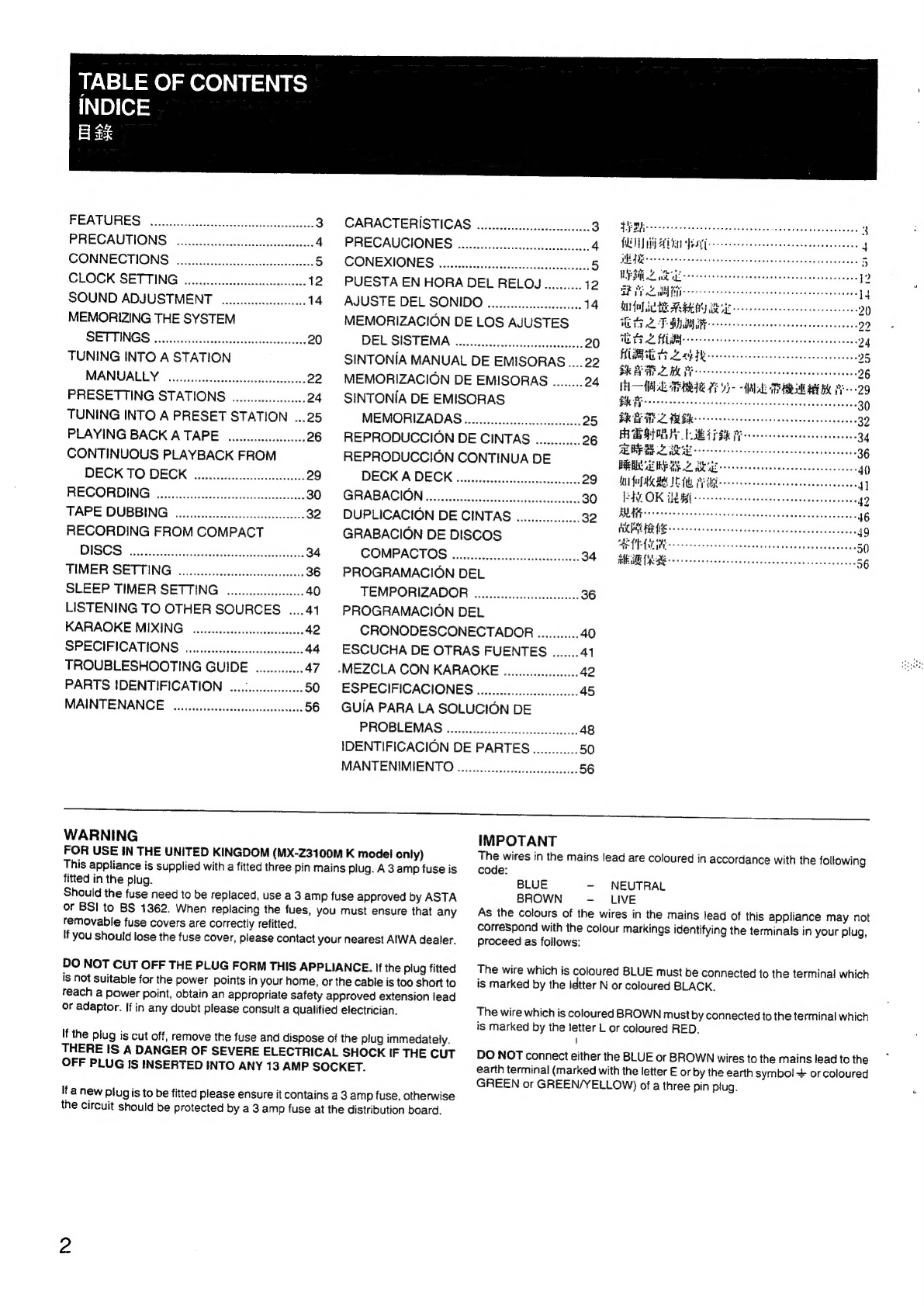
INDICE
EB
8k
FEATURES:
sti
pivantiialeidccstenaien
3
CARACTERISTICAS
......sccccscscessesseeeeee
I
Ee
3
PRECAUTIONS
iicsiscitadcuntssiaiieonts
4
PRECAUCIONES
..00.....eeccsecccscsssseecsseeees
4
PRINT
APT
Pesto
earpsteeeeesceccasepsssenese
4
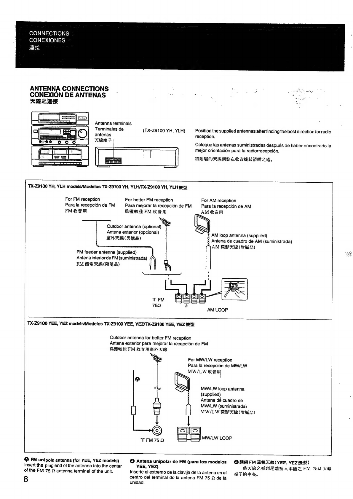
CONNECTIONS
..sccccsssecessssssnsseseeee
5
—
CONEXIONES
asessssscssssecssccesssesnseccnsnse
5
he
ee
;
CLOCK
SETTING
ooe.cccccccsssssscssssseceseeeen
12
PUESTA
EN
HORA
DEL
RELOJ..........
V2
ea
Pia
daidass
asses
cs
eancid
se
cae
eens
2
SOUND
ADJUSTMENT
o.oo
14
AJUSTE
DEL
SONIDO
ow...
eee
14
GUO
SRE
RENY
Beye
ne
ceeeeceeeceeeeeeseeeeeeee
2
MEMORIZING
THE
SYSTEM
MEMORIZACION
DE
LOS
AJUSTES
Oa
a
22
SEUINGS
csoittcesacn
atin
ocd
20
DEL
SISTEMA
sists
ssadesiscsuststecsine
7s
i
OL
a
ae
24
TUNING
INTO
A
STATION
SINTONIA
MANUAL
DE
EMISORAS
.....22
Lt
aN
EERE
MANUALLY
oun.
ecececcseccscseseseeeeeees
22
MEMORIZACION
DE
EMISORAS
........
24
HAL
TERA
Fe
Y-
“AAV
di
TEAS
LEY
Bie
PH
-99
PRESETTING
STATIONS
oo...
24
SINTONIA
DE
EMISORAS
BR
EG
crete
tee
tcereseeeneeneeneeneeneeeteneeey
30
TUNING
INTO
A
PRESET
STATION
...25
MEMORIZADAS......seesssessccsseseseecen
20
ee
RCS
asthe
32
PLAYING
BACK
A
TAPE.
scscscucssse
26
REPRODUCCION
DE
CINTAS
........
20
ee
a
er
a
CONTINUOUS
PLAYBACK
FROM
REPRODUCCION
CONTINUA
DE
HARI
SERGE
DBE
GE
eseeeceesseseveersaceseeseense.
40
DECK
TO
DECK
..ecseseseseesseseeseveeees
29
DECK
A
DECK
o.sssssesssssssscsssssneseseesees
29
FNAME
UL
PUB
ee
eeeeeeeneees
4
RECORDING
scniSuiieehitsicchiieaiecs:
80>
.GRABACION
ec
ctesinst
csi
diamaneeten
BO
IAL
OK
IRM
recesses
ere
teeeeseeens
42
TAPE
DUBBING
...cccccccsssssssssssssssseeeee
32
DUPLICACION
DE
CINTAS
seen
32
op
RECORDING
FROM
COMPACT
GRABACION
DE
DISCOS
DEY
ed
oxsscoss
endl
Acite
ic
ec.
2
DISCS
*sbecsssccitecsviceves
cbviateiesedstaeeisces
34
COMPACTOS
......ocececcccceesceseeseens
34
MESURE
ee
ccc
ceeesensccssscenaaccescecsateesece
56
TIMER
SETTING
....ccccccccccccccesseeseseen
36
PROGRAMACION
DEL
SLEEP
TIMER
SETTING
ooo.
40
TEMPORIZADOR
......ccccccccscssesessssee
36
LISTENING
TO
OTHER
SOURCES
....41_
PROGRAMACION
DEL
KARAOKE
MIXING
..-ccssssssssesssssssssssees
42
CRONODESCONECTADOR...........
40
SPECIFICATIONS.
......eeessssscccssscssseeeeeee
44
ESCUCHA
DE
OTRAS
FUENTES
.......41
TROUBLESHOOTING
GUIDE
.............
47
.MEZCLA
CON
KARAOKE
........sscessesss
42
PARTS
IDENTIFICATION
.....scssssssssssen
50
ESPECIFICACIONES
..0.........ccsssseeeeeee
45
MAINTENANCE.
o....ssesseesseeecsseeeeseteans
56
GUIA
PARA
LA
SOLUCION
DE
PROBLEMAS
.......sceescccscssssssssseeeseees
48
IDENTIFICACION
DE
PARTES............
50
MANTENIMIENTO
.......ssscescscscsssssssseeeee:
56
WARNING
FOR
USE
IN
THE
UNITED
KINGDOM
(MX-Z3100M
K
model
only)
This
appliance
is
supplied
with
a
fitted
three
pin
mains
plug.
A
3
amp
fuse
is
fitted
in
the
plug.
Should
the
fuse
need
to
be
replaced,
use
a
3
amp
fuse
approved
by
ASTA
or
BSI
to
BS
1362.
When
replacing
the
fues,
you
must
ensure
that
any
removable
fuse
covers
are
correctly
refitted.
If
you
should
lose
the
fuse
cover,
please
contact
your
nearest
AIWA
dealer.
DO
NOT
CUT
OFF
THE
PLUG
FORM
THIS
APPLIANCE.
If
the
plug
fitted
is
not
suitable
for
the
power
points
in
your
home,
or
the
cable
is
too
short
to
reach
a
power
point,
obtain
an
appropriate
safety
approved
extension
lead
or
adaptor.
If
in
any
doubt
please
consult
a
qualified
electrician.
If
the
plug
is
cut
off,
remove
the
fuse
and
dispose
of
the
plug
immedately.
THERE
IS
A
DANGER
OF
SEVERE
ELECTRICAL
SHOCK
IF
THE
CUT
OFF
PLUG
IS
INSERTED
INTO
ANY
13
AMP
SOCKET.
Ifanew
Plug
is
to
be
fitted
please
ensure
it
contains
a
3
amp
fuse,
otherwise
the
circuit
should
be
protected
by
a
3
amp
fuse
at
the
distribution
board.
IMPOTANT
The
wires
in
the
mains
lead
are
coloured
in
accordance
with
the
following
code:
BLUE
-
NEUTRAL
BROWN
-
LIVE
As
the
colours
of
the
wires
in
the
mains
lead
of
this
appliance
may
not
correspond
with
the
colour
markings
identifying
the
terminals
in
your
plug,
proceed
as
follows:
The
wire
which
is
coloured
BLUE
must
be
connected
to
the
terminal
which
is
marked
by
the
idtter
N
or
coloured
BLACK.
The
wire
which
is
coloured
BROWN
must
by
connected
to
the
terminal
which
is
marked
by
the
letter
L
or
coloured
RED.
t
DO
NOT
connect
either
the
BLUE
or
BROWN
wires
to
the
mains
lead
to
the
earth
terminal
(marked
with
the
letter
E
or
by
the
earth
symbol
+
or
coloured
GREEN
or
GREEN/YELLOW)
of
a
three
pin
plug.