Akai MPD218 User manual

SPECIFICATIONS
Pads
PadsPads
Pads
16
16 16
16
velocity- and pressure-sensitive pads, red-backlit
3
3 3
3
banks accessible via
Pad Bank
Pad Bank Pad Bank
Pad Bank
button
Knobs
KnobsKnobs
Knobs
6
6 6
6
360° assignable potentiometers
3
3 3
3
banks accessible via
Control Bank
Control Bank Control Bank
Control Bank
button
Buttons
ButtonsButtons
Buttons
6
6 6
6
buttons
Connections
ConnectionsConnections
Connections
1
1 1
1
USB port
1
1 1
1
Kensington lock
Power
PowerPower
Power
via USB connection
Dimensions
DimensionsDimensions
Dimensions
( idth x depth x height)
9.4” x 7.9” x 1.6”
23.9 cm x 20.1 cm x 4.1 cm
Weight
WeightWeight
Weight
1.65 lbs.
0.75 kg
SERVICE MANUAL
MODEL:
MPD218

DISASSEMBLY PROCEDURES
1.
DISASSEMBLE THE BOTTOM PANEL AND KNOB.
(A) REMOVE 6 KNOBS, 6 NUTS AND 6 WASHERS FROM THE TOP PANEL.
(B) REMOVE 11 SCREWS FROM THE BOTTOM PANEL.
(Fig1)
2.
DISASSEMBLE THE FUNCTION PCB ASSEMBLY AND FSR PCB ASSEMBLY.
(A) UNPLUG 2 PCS FFC CABLE FROM THE FSR PCB ASSEMBLY AND FUNCTION PCB ASSEMBLY.
(B) REMOVE 8 SCREWS FROM THEFSR PCB ASSEMBLY.
(C)REMOVE 4 SCREWS FROM THE FUNTION PCB ASSEMBLY.
(Fig2)

WIRING DIAGRAM
(US/AU)

PACKING DIAGRAM
(US/AU)

EXPLODE DIAGRAM
(US/AU)
EQUENCIAL NO EXPLODE DIAGRAM WILL BE MARKED ON REF.COLUMM OF BOM LIST

AD18AKA21 BOM
LEVEL
P/N DESCRIPTION QTY
REF
0 AD18AKA21 AD18 USB5V USA 0
1 AA821535X USB 2.0 Cable 1m A/B Type Black 1
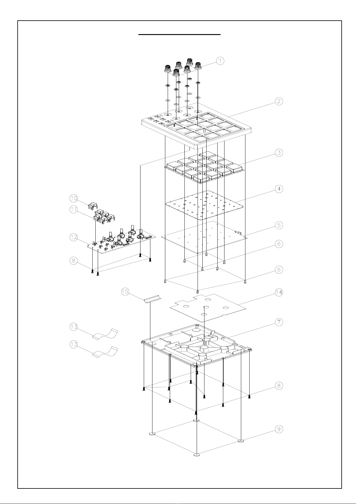
1 EVA1504476 EVA(50x15mm) 1 15
1 EVA1504479 EVA 1 14
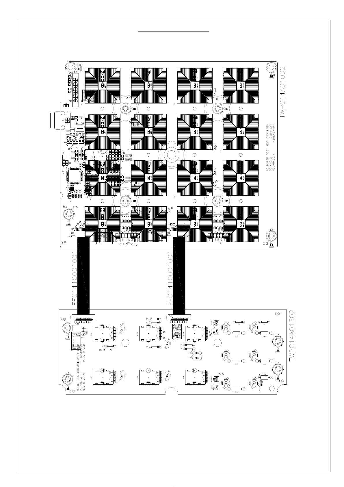
1 FFC1410001001 FFC 14P Pitch:1.0mm Length:100mm 2 13
1 GEAKA17 Ableton Card 1
1 LAC22AKA370 Serial Number Label 1
1 LAC22AKA42 Sticker S/N Ableton 1
1 LAC46AKA393 Istruction Label(IOS MODE) 1
1 LAC57AKA398 Safety Label 1
1 LAC62AKA369 Bar Code Label(CODE39) 0.1
1 LAC62AKA371 Bar Code Label(GTIN14) 0.1
1 LAC67YAH261 Label φ8mm Green 0.1
1 OTFSR16KEY-AD33 FSR 16KEY 1 4
1 PAD18AKA21 Packing Assembly 1
2 AL7-51-0226-M Safety Manual 1
2 CGAD18310AKA01 Gift Box 1
2 CTAD18513AKA01 Shipping Carton 0.1
2 GEAKA20 Generic Card 1
2 OPAD18AKA01 Instruction Book 1
2 PE230190402B07 Pe Bag 1
2 PLAD1801 Poly Foam(Left) 1
2 PLAD1802 Poly Foam(Right) 1
2 SD30026010 Soft Sheet Bag 1
1 PT15106125 Button(B;clear) 1 10
1 PT15106150 Knob 6 1
1 PT15106191 Button(Black) 5 11
1 PT153004401 Top Panel(Print/Paint) 1 2
2 PT1530044 Top Panel 1
1 PT1530336 Bottom Panel 1 7
1 RU1110670 Rubber Foot 4 9
1 RU1510638 Rubber Knob 1 3
1 SC0308PBBI Screw M3X8 PBB Tapping 15
8
1 SC2605PBBI Screw M2.6x5 PBB Tapping 8 6
1 TWPC14A01002 FSR PCB Assembly 1 5
2 AL2-49-0070 Diode BAV70 8 D13~20
2 AL2-51-4403 Transistor 2N4403 PNP SOT-23 16
Q1~16
2 AL2-61-7223 IC NJU7223DL1-33 3.3V TO-252 1 U2
2 AL2-71-1324 IC LMV324 SOP-14 1 U5
2 AL4-08-0402 Con USB 4-Pin Female PC-MNT Horizontal 1 J1
2 CS102J5003NPO CCAP SMD 1nF/50V 5% 0603 NPO 4 C31~34
2 CS103K5003X7R CCAP SMD 0.01uF/50V 10% 0603 X7R 21
C8,15~20,42,43,50~57,82,84,86,88
2 CS104K5003X7R CCAP SMD 0.1uF/50V 10% 0603 X7R 12
C1,3,4,5,7,10~12,26,29,30,58
2 CS106K0605X5R CCAP SMD 10uF/6.3V 10% 0805 X5R 6 C9,13,14,22,35,36
2 CS180J5003NPO CCAP SMD 18pF/50V 5% 0603 NPO 2 C2,6
2 CS561J5005NPO CCAP SMD 560pF/50V 5% 0805 NPO 4 C81,83,85,87
2 FCN1T1001402 FCN DOWN Touch ZIF SMD Pitch=1.0mm 14P 2 J3,4
2 IC74HC595 Integrated Circuit 2 U1,3

2 ICYH103M13 IC(STM32F102RBT6+Program)TQFP-64 1 U4
3 ICSTM32F102RBT6 IC STM32F102RBT6 TQFP-64 1 (U4)
2 LDKPT-1608SURCK Liquid-emitting Diode Red SMD 0603 16
LED17~32
angle 120°
2 PC14A010 FSR PCB 2Layer FR-4 187x156mm 1.6T 1 -
2 RS000008J05 RES 0Ω5% SMD 0805 5 R2,14,17,18,28
2 RS001K08F05 RES 1K 1% SMD 0805 16
R67~82
2 RS002208F05 RES 22Ω1% SMD 0805 2 R5,6
2 RS004710F03 RES 47Ω1% SMD 0603 1 R26
2 RS006808F05 RES 68Ω1% SMD 0805 16
R27,29~33,57~66
2 RS010008F05 RES 100Ω1% SMD 0805 1 R34
2 RS010K08F05 RES 10K 1% SMD 0805 9 R8,11,15,16,19,22,500,501,502
2 RS01K508F05 RES 1.5K 1% SMD 0805 5 R1,3,4,7,9
2 RS022008F05 RES 220Ω1% SMD 0805 5 R10,12,13,20,21
2 RS047008F05 RES 470Ω1% SMD 0805 4 R37,38,39,40
2 RS06K808F05 RES 6.8K 1% SMD 0805 4 R23,24,35,36
2 XTM08000X6F1 Crystal 8MHZ 49US SMD Fundamental 1 X1
1 TWPC14A01302 Function PCB Assembly 1
2 AL3-02-0035 LIQUID-EMITTING DIODE RED ASTIGMATISM 4 LED200~203
DIP
2 BALE42206-0A LED Holder 4 (LED200~203)
2 BALED2X2 LED FIXED PLATE 1 (LED204)
2 CC10450T C.CAP 0.1UF/50V 6 C200,203,206,210,213,216
2 EC10616TS Capacitor Electrolytic 10uF/16V 4*5mm 1 C201
2 FCN2R1001401 FCN Dual Touch 90°Pitch:1.0mm 14P 2 J200,201
2 JW5206T Jumping Wire 9 J1~9
2 LD-005HLV Red LED 1 LED204
2 PC14A013 Main PCB 1Layer FR-1 1.6T 187x68mm 1 -
2 R10316 RES 10K 1/8W 6 R210~215
2 SWEVQ11L04M Switch Tact 4.3mm 160g Horizontal DIP 6 SW200~205
2 VRR12302501 Potentiometer Rotary 12.5k 2B*2 25mm 6 R200~205

Manufacturing Testing of MPD218 using ADT1
15 October, 2014
This document is intended to describe the operation of the ADT1 Manufacturing Test
application for the Production Testing of MPD218.
Terms
MPD218: A US Pad Controller. Also known as AD18.
ADT1: A Manufacturing Test application that runs on Windows computers.
Hardware setup
Connect MPD218 US to Windows Computer running ADT1 Manufacturing Test
application.
Software setup
The Manufacturing Test of AD18 requires the following files
–ADT1.exe: executable file (v.0.7.3 or later)
–AD18.png: image file
–AD18.xml: test file
These files should be arranged so that the product specific files (AD18.png and AD18.xml)
are in a folder called “tests” that resides in the same folder as the ADT1 executable as
below.
Running the Manufacturing Test Application
Port selection
Different language versions of different Operating Systems have different ways of
identifying MIDI ports and audio hardware. For this reason, ADT1 allows the Tester to
select these ports when the program is first run. Once a subtest has been successfully
completed, it should no longer be necessary to select these ports even if a different unit is
being tested.
The ports that need to be selected depend on the sub-tests that are being performed for
that product. In addition to the main US -MIDI port, the Manufacturing test for MPD218
requires that a port be selected for the MIDI loopback test.

Device Test selection
When the program starts on an English language version of Windows XP, the Tester
should be presented with the following “Port/Test Chooser” window.
Select the correct port and test and click “OK”. This selection should only need to be done
once when the program is first run.
User Interface
The Main Test screen has a representation of the Device Under Test.

Subtest buttons
At the bottom of the screen are some buttons that correspond to “sub-tests”. These might
be tests of faders, LEDs, etc. The button will be
–grey if the subtest has not started
–yellow if the sub-test is in progress
–green if the test has subtest has completed successfully
–red if the subtest has failed.
Normally the order of the test will follow the order of the subtest buttons, but it is possible
to change the order of the tests by clicking on the buttons. This can be useful if a test is
accidentally failed.
When the the right-most subtest is completed, the Test Application will loop back to repeat
any tests that have not completed successfully.
The option to write a Serial Number into the Device Under Test will not be offered until
every subtest has been completed successfully (i.e. every subtest button is green).
Serial Number
When a test starts, the Serial Number of the MPD218 will be read and displayed in the
bottom left corner.
The Serial Number will also be read from the MPD218 and displayed after Serialisation
has completed.
Version Number
The version of the firmware will be displayed in the bottom right hand corner.
Indicators
Wherever possible the ADT1 Manufacturing Test app will prompt the Tester. This might be
to show which LEDs should be flashing, which buttons should be used to confirm the test
result or which fader, knob, etc. has been tested.

Tests
LED tests
There are two LED tests in the MPD218 Manufacturing Test.
–utton LEDs
–Pad LEDs

In each case, the ADT1 Manufacturing Test app will send a message to flash LEDs on the
MPD218. The User interface will indicate which LEDs are flashing and what colour they
should be. The Tester should indicate whether the test passed by pressing the UI controls
indicated by the “bubble” messages.
–Test Passed: press the control indicated by “PASS” bubble message.
–Test Failed: press the control indicated by “FAIL” bubble message.
The LED Test has two phases:
1. Animated test where the LEDs are lit one at a time. This is to check for shorts
between LEDs.
2. ALL_LEDS_ON test where all the LEDs are lit. This is to help check for faulty
LEDs.

Button Test
The ADT1 manufacturing Test application will indicate the buttons to be pressed. The
Tester should individually press and release the indicated buttons.
When the ADT1 manufacturing Test application detects that the button has been pressed it
will change the graphic symbol on the User Interface and, where possible, it will send a
message to light the LED that is associated with the button on the MPD218.
The buttons can be pressed in any order, but if ADT1 detects two button events at exactly
the same time it will assume that these buttons are shorted together and fail the test.

Pad test
The Tester should firmly press the indicated pad. The test requires that a maximum pad
pressure value is received by the ADT1 Manufacturing Test application.
When the ADT1 Manufacturing Test application detects light pressure it will change the
graphic symbol on the User interface and send a message to the MPD218 to light the
associated Pad LED.
When the ADT1 Manufacturing Test application detects maximum pad pressure, it will
change the graphic symbol to green and send a message to the MPD218 to switch off the
associated Pad LED.

Rotary Encoder test
The Tester needs to turn the encoder first clockwise and the anti-clockwise as indicated by
the ADT1 Manufacturing Test application.
When the ADT1 Manufacturing Test application detects clockwise rotation of the Rotary
Encoder, it will change the graphic symbol on the User interface.

Serialisation
When all the subtest have been successfully completed, the subtest buttons on the User
Interface will be removed and replaced with a text box. This text box should be used to
program the Serial Number into the MPD218.
The Tester can type the Serial Number, followed by Carriage Return, but it is preferred that
a US arcode Reader is used to scan the serial number barcode on the MPD218.
When the Serialisation has completed successfully, the display will update.
–The word “Programmed will appear next to the Serial Number box
–The new Serial Number will appear in the bottom left corner (this is important)
–A green tick will appear next to the Progress ar
–The top line will say “PASSED”

Test Complete - Next MPD218
When a test of a MPD218 is complete, either successful or unsuccessful, it should be
possible to just disconnect that MPD218 and connect the next one. It would not normally
be necessary to reselect the ports as long as the corresponding test on the previous
MPD218 were successful.


Other manuals for MPD218
5
Table of contents
Other Akai Recording Equipment manuals

Akai
Akai ADVANCE 49 User manual

Akai
Akai Professional LPK25 User manual

Akai
Akai S6000 User manual

Akai
Akai EA-A2 User manual

Akai
Akai MPC User manual

Akai
Akai MPC 2500 How to use

Akai
Akai MPK 61 User manual

Akai
Akai MPC 5000 User manual

Akai
Akai S1000 Series User manual

Akai
Akai MPC 2500 Installation and operating instructions