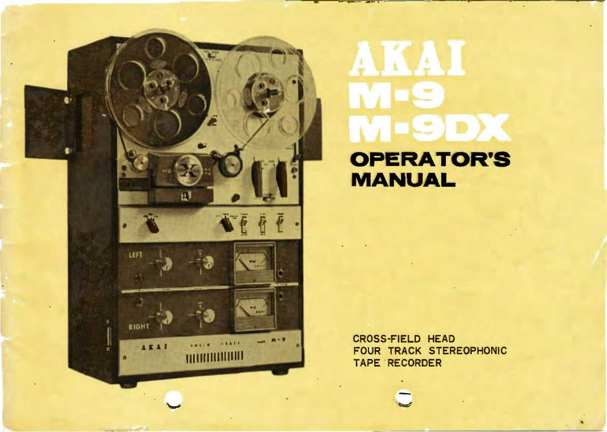
AKAI M-9 · M-9DX
TABLE
OF
CONTENTS
' '
•,
I GENERAL INFORMATION
1.
Specifications ············..················ 2
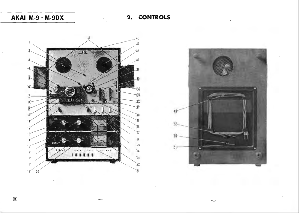
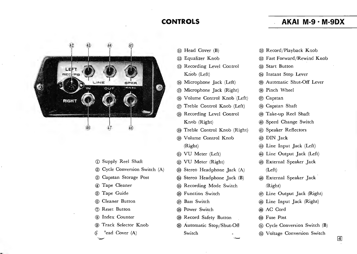
2.
Controls
······································· 3
3.
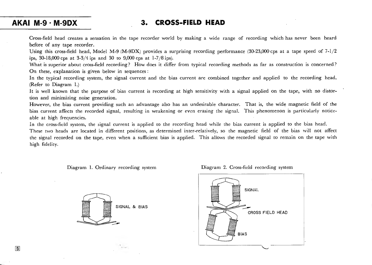
Cro
ss
field
Head
························ 5
4. Recor
ding
/
Pla
y
ba
ck
for 4
tr
ac
k ········· 6
5.
Operationa1
Prec
aut
ion
s ··..··········· 7
6.
Voltage
and
Cycle
Con
version······ 8
7.
Selection
oC
Tape
Speeds
··
··
······
·· g
8.
Pla
y
back
using
External
Speakers···
10
9.
DI
N (
One
Multiple
Connection)
J
ac
k ·········
10
10.
Tape
Cl
ea
ner ························ ······
Il
J[
OPERATING INSTRUCTIONS
1.
Thrc:1ding the
Tape···
·················· 12
2.
Stereo
Pla
yb
ac
k ············ ··· ············ 12
3.
Au
toma
tic
Stop
/.3hut·
Üff
····· ······. 13
4.
I
nstant
Stop
Control
··· ············ ·· · 13
5.
Ster
eo
Recordin
g ························ 14
6. R
ecor
din
g from
Ster
eo
Broadcast··· 15
7.
Recor
din
g
li
·
om
Stereo
Dises········· 15
8.
Mona
ur
al Rcco
rdin
g
on
Tr
acks
No.
1-
4 ·····
····
15
9.
Monaura1
Rec
ording
on
Track
s
No.
3 2 ·
········
16
10.
Monaura1
Pl
aybac
k ··· ·····
·······
······ 17
Il.
Tape
Erasing
······························
17
12.
fast
Forward
and
Rew
ind
············ 18
13.
Monitoring
··..····························· 18
1
4.
Tape
Splicing
and
Editing
············
18
15.
Cleaning
Head
............
·············..
19
16
.
Head
D
emagnet
i
za
ti
on
......
.........
21
17
. T
ape
Dupli
ca
tion
............
............ 21
18
.
Sound
on So
und
························
22
19
.
Transistor
Pro
tccti
o:1
··················
23
JI[
ACCESSORIES
1.
Accessori
es
Optiona
1·
····
·······
·········
24
2. Accessori
es
Standa
rd
······
·
·········
·····
25
lV
SCHEMATIC