Akai MPD226 User manual

SPECIFICATIONS
Pads
PadsPads
Pads
16
16 16
16
velocity- and pressure-sensitive pads, RGB-backlit
4
4 4
4
banks accessible via
Pad Bank
Pad Bank Pad Bank
Pad Bank
button
Knobs
KnobsKnobs
Knobs
4
4 4
4
360° assignable potentiometers
3 banks accessible via Control Bank button
3 banks accessible via Control Bank button3 banks accessible via Control Bank button
3 banks accessible via Control Bank button
1
1 1
1
360° encoder for display navigation and selection via push
Buttons
ButtonsButtons
Buttons
4
4 4
4
assignable s itches, amber-backlit
10
10 10
10
dedicated function buttons, amber-backlit
3
3 3
3
transport buttons
4
4 4
4
directional cursor buttons for display navigation
Display
DisplayDisplay
Display
20
20 20
20
x
4
4 4
4
characters, monochrome backlit ith adjustable contrast
Connections
ConnectionsConnections
Connections
1
1 1
1
USB port
1
1 1
1
po er input (po er adapter sold separately)
1
1 1
1
1/8” MIDI input (1/8”-MIDI adapter included)
1
1 1
1
1/8” MIDI output (1/8”-MIDI adapter included)
1
1 1
1
Kensington lock slot
Power
PowerPower
Power
via computer USB bus or USB charger (sold separately)
via po er adapter (sold separately): 6V DC, 1A, center-positive
Dimensions
DimensionsDimensions
Dimensions
(width x depth x
height)
13.1” x 10.0” x 1.9”
33.3 cm x 25.4 cm x 4.8 cm
Weight
WeightWeight
Weight
2.9 lbs.
1.3 kg
SERVICE MANUAL
MODEL:
MPD2
26

DISASSEMBLY PROCEDURES
1.
DISASSEMBLE THE BOTTOM PANEL, KNOB AND SLIDER VR CAP.
(A) REMOVE 5 KNOBS, 5 NUTS, 5 WASHERS AND 4 PCS SLIDER VR CAP FROM THE TOP PANEL.
(B) REMOVE 13 SCREWS FROM THE BOTTOM PANEL.
(Fig1)
2.
DISASSEMBLE THE TOP PCB ASSEMBLY, FSR PCB ASSEMBLY AND LCM.
(A)REMOVE 2 PCS CABLE FROM THE TOP PCB ASSEMBLY AND FSR PCB ASSEMBLY.
(B)REMOVE 11 SCREWS FROM THE TOP PCB ASSEMBLY.
(C)REMOVE 4 SCREWS FROM THE LCM.
(D)REMOVE 8 SCREWS FROM THE FSR PCB ASSEMBLY.
(Fig2)

WIRING DIAGRAM
(US/AU)

PACKING DIAGRAM
(US/AU)

EXPLODE DIAGRAM
(US/ AUS)
EQUENCIAL NO EXPLODE DIAGRAM WILL BE MARKED ON REF.COLUMM OF BOM LIST

AD27AKA21 BOM
LEVEL
P/N DESCRIPTION QTY
REF
0 AD27AKA21 AD27 USB5V USA 0
1 AA821535X USB 2.0 Cable 1m A/B Type Black 1
1 BASJ5012B PU Stand 6
10
1 CA030000503 TRS Cable 50mm 3.5φ/MIDI Type Black 2
1 CN0100000501 Flat Cable GND Wire Black Length 50mm 1
24
Line/Female
1 EVA1504479 EVA 1
1 FFC1610000501 FFC 16Pin Pitch:1.0mm Length:50mm 1
20
1 FFC1610001501 FFC 16Pin Pitch:1.0mm Length:150mm 1
21
1 GEAKA17 Ableton Card 1
1 GEAKA20 Generic Card 1
1 LAC22AKA365 Serial Number Label 1
1 LAC22AKA42 Sticker S/N Ableton 1
1 LAC46AKA390 Istruction Label(IOS MODE) 1
1 LAC57AKA399 Safety Label 1
1 LAC62AKA366 Bar Code Label(CODE39) 0.5
1 LAC62AKA372 Bar Code Label(GTIN14) 0.5
1 LAC67YAH261 Label φ8mm Green 0.5
1 LCMWH2004B LCM WDH0235-TMI-JTV 6O'clock 1
13
1 NM1504403 FELT-45-ADHESIVE 4
22
1 NP215AKA41 Name Plate 1
12
1 OTFSR16KEY-AD33 FSR 16KEY 1
5
1 PAD27AKA21 Packing Assembly 1
2 AL7-51-0226-M Safety Manual 1
2 CGAD27310AKA01 Gift Box 1
2 CTAD27513AKA01 Shipping Carton 0.5
2 OPAD27AKA01 Instruction book 1
2 PE230190402B07 Pe Bag 1
2 PLAD2701 Polyfoam(Left) 1
2 PLAD2702 Polyfoam(Right) 1
2 SD38030000 Soft Sheet 1
1 PT1110685 Button Push 6
15
1 PT1504329 Light Pipe 7
25
1 PT1510611001 Power Button(Painting) 1
23
2 PT15106110 Power Button 1
1 PT1510611301 Knob Print 1
11
2 PT15106113 Knob 1
1 PT15106125 Button(B;clear) 8
1 PT15106150 Knob 4
1
1 PT15106151 Buttom(B;Cool Gray 6C) 2
16
1 PT15106192 Button(Pantone 187C) 1
18
1 PT151063801 FADER INDICATE PAINTING WHITE 4
2
2 PT1510638 FADER 4
1 PT151063904 Bottn Cursor(Black)Printing 1
17
2 PT1510639 BUTTON CURSOR(BLACK) 1
1 PT153004302 Top Panel(Print/Paint) 1
3
2 PT1530043 Top Panel(Black) 1
1 PT1530335 Bottom Panel(Red) 1
8
1 RU1510638 Rubber Knob 1
4

1 SC0208RBCI Screw M2X8 PPC Tapping 4
14
1 SC0308PBBI Screw M3X8 PBB Tapping 24
9
1 SC2605PBBI Screw M2.6x5 PBB Tapping 8
7
1 TWPC14A01101 TOP PCB Assembly 1
19
2 AA822524X IC SN74HC165PW 3
U1~3
2 AA822748X Diode BAV99 2
D2,3
2 AL0-17-0101 RES Array 4X100 1/10W 0603 3
R6,78,103
2 AL0-17-0221 RES ARRAY 4X220 1/10W 0603 3
R11,12,13
2 AL0-17-0331 RES Array 4X330Ω1/10W 0603 2
R121,122
2 AL2-50-4149 Diode Single 1N4148 100V 200mA SOT-23 1
D8
2 AL2-51-0140 Schottky Barrier Rectifiers Diode 2
D6,10
B140-13-F SMA
2 AL2-51-4401 Transistor 2N4401 NPN SOT-23 (Transistor 6
Q2,6,8,9,11,14
MMBT4401LT1 NPN SOT-23)
2 AL2-51-4403 Transistor 2N4403 PNP SOT-23 8
Q1,3~5,7,10,12,13
2 AL2-52-5242 Diode MMBZ5242B 1
D5
2 AL2-54-6306 Mosfet FDC6306P P-CH SSOT-6 1
U7
2 AL2-61-7223 IC NJU7223DL1-33 3.3V TO-252 1
U6
2 AL2-62-0004 IC 74AHC04 1
U22
2 AL4-08-0402 Con USB 4-Pin Female PC-MNT Horizontal 1
J6
2 CN0100000501 Flat Cable GND Wire Black Length 50mm 1
TP1
Line/Female
2 CS102J5003NPO CCAP SMD 1nF/50V 5% 0603 NPO 13
C12,13,18,61,62,64,68,73,91,103~106
2 CS102J5005NPO CCAP SMD 1nF/50V 5% 0805 NPO 3
C43,63,65
2 CS103K5003X7R CCAP SMD 0.01uF/50V 10% 0603 X7R 4
C42,89,92,94
2 CS104K5003X7R CCAP SMD 0.1uF/50V 10% 0603 X7R 49
C5~8,15~17,21,23,26~37,39~41,44,45~47
C51~56,58~60,66,67,69,70,72,90,93,95
C101,107,163,171
2 CS105K1003X5R CCAP SMD 1uF/10V 10% 0603 X5R 3
C9,177,178
2 CS105K2505X7R CCAP SMD 1uF/25V 10% 0805 X7R 1
C57
2 CS106K0605X5R CCAP SMD 10uF/6.3V 10% 0805 X5R 6
C3,19,20,22,50,176
2 CS180J5003NPO CCAP SMD 18pF/50V 5% 0603 NPO 2
C25,49
2 CS475K1605X5R CCAP SMD 4.7uF/16V 10% 0805 X5R 1
C48
2 DIBAW56 Switch Diode BAW56 SOT-23 2
D1,4
2 DIPHLTV-356T-B optical coupler Diode LTV-356T-B 1
SEN2
2 DIZDSMAJ10ASM Diode 11.5V 400W 23A 1
D21
2 ECS10710D Capacitor Electrolytic 100UF 10V SMD-D 3
C38,165,181
2 FCN1R1001605 FCN UP Touch smd Pitch 1.0mm 16Pin have 1
J19
latch
2 FCN1T1001602 FCN Down Touch ZIF SMD Pitch=1.0mm 16P 1
J3
2 IC4052BFN IC 74HC4052DT Dual 4-channel Analog 2
U9,14
Multiplexer/Demultiplexer SOP-16
2 IC74HC574D INTEGRATED CIRCUIT 1
U10
2 IC74HC595 Integrated Circuit 3
U62~64
2 ICLM393DR IC OPA LM393DR SOIC-8 1
U8
2 ICNJM2387 IC NJM2387 1
U59
2 ICSN74HC02D IC SN74HC02DR SOIC-14 1
U4
2 ICYH103M09 IC(STM32F102RBT6+Program V1.00)TQFP-64 1
U11
3 ICSTM32F102RBT6 IC STM32F102RBT6 TQFP-64 1
(U11)
2 JKDJ-0702B-020 DC Base 2.0MM 1
J7
2 JKK3J15S 1/8" Headphone Jack 2
J1,2

2 LDKPT-1608SYCK Liquid-emitting Diode Yellow SMD 0603 19
LED1~7,9~20
angle 120°
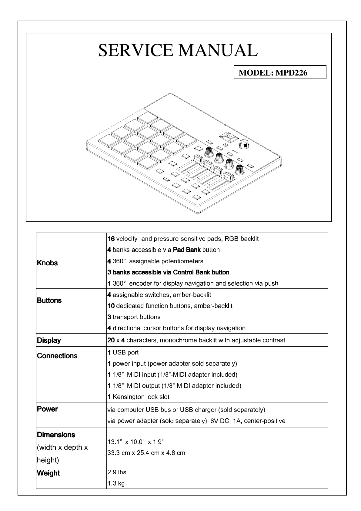
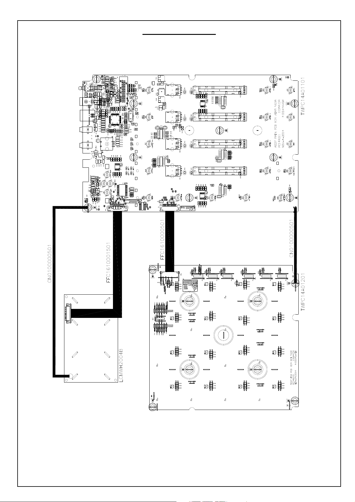
2 PC14A011 TOP PCB 2Layer FR-4 1.6T 255*165MM 1
-
2 RS000008J05 RES 0Ω5% SMD 0805 15
R10,27,60,61,63,66,99,101,127,132,133
R139,142,148,162
2 RS001508F05 RES 15Ω1% SMD 0805 1
R153
2 RS001K08F05 RES 1K 1% SMD 0805 3
R128~130
2 RS001K10F03 RES 1K 1% SMD 0603 1
R165
2 RS002208F05 RES 22Ω1% SMD 0805 2
R72,73
2 RS004708F05 RES 47Ω1% SMD 0805 9
R1,7,74,76,77,163,167,173,176
2 RS010008F05 RES 100Ω1% SMD 0805 10
R2,15~17,21~25,172
2 RS010K08F05 RES 10K 1% SMD 0805 57
R3~5,8,9,14,18~20,26,35,62,64,67,70,71
R79~90,94,95,97,102,105,115,117,119,123
R126,134,138,140,141,143~145,149~151
R156,159~161,164,171,501~503
2 RS012K08F05 RES 12K 1% SMD 0805 1
R146
2 RS01K108F05 RES 1.1K 1% SMD 0805 1
R137
2 RS01K508F05 RES 1.5K 1% SMD 0805 1
R147
2 RS022008F05 RES 220Ω1% SMD 0805 3
R168~170
2 RS027010F03 RES 270Ω1% SMD 0603 1
R75
2 RS047008F05 RES 470Ω1% SMD 0805 1
R152
2 RS047508F05 RES 475Ω1% SMD 0805 1
R136
2 RS068008F05 RES 680Ω1% SMD 0805 1
R157
2 RS080608F05 RES 806Ω1% SMD 0805 1
R135
2 RS100K08F05 RES 100K 1% SMD 0805 2
R69,155
2 RS220K08F05 RES 220K 1% SMD 0805 3
R68,124,125
2 RS2K1508F05 RES 2.15K 1% SMD 0805 1
R166
2 RS4K7508F05 RES 4.75K 1% SMD 0805 1
R158
2 RS820K08F05 RES 820K 1% SMD 0805 1
R131
2 RS8K0608F05 RES 8.06K 1% SMD 0805 1
R154
2 SWDC11B20214A8 Switch Rotatiomal 20 pulse 20mm push-on 1
E1
switch
2 SWEVQ11L04M Switch Tact 4.3mm 160g Horizontal DIP 21
SW0~20
2 SWSPPJ22ME04 Switch Push 2P2T Dual Row Lock 1
SW21
2 UHBLM18AG102SN1 BEAD 1000Ω100MHZ 1
L7
2 UHCBC3225T100MR INDUCTOR 10UH 0.9A 0.133OHM 20% 1210 2
L1,2
2 VRR12302501 Potentiometer Rotary 12.5k 2B*2 25mm 4
R32,44,65,91
2 VRS10304533 Potentiometer Slide 10K 2B 45mm 15mm 4
R107,109,116,118
Dual Unit
2 XTM08000X6F1 Crystal 8MHZ 49US SMD Fundamental 1
X1
1 TWPC14A01201 FSR PCB Assembly 1
6
2 AL2-49-0070 Diode BAV70 8
D200~207
2 AL2-71-1324 IC LMV324 SOP-14 1
U200
2 CS103K5003X7R CCAP SMD 0.01uF/50V 10% 0603 X7R 4
C204~207
2 CS104K5003X7R CCAP SMD 0.1uF/50V 10% 0603 X7R 7
C208,211~216
2 CS106K0605X5R CCAP SMD 10uF/6.3V 10% 0805 X5R 4
C209,210,217,218
2 CS561J5005NPO CCAP SMD 560pF/50V 5% 0805 NPO 4
C200~203
2 FCN1T1001602 FCN Down Touch ZIF SMD Pitch=1.0mm 16P 1
J200
2 IC74HC595 Integrated Circuit 6
U201~206
2 LDG1F1A1BB8S3S3 Liquid-emitting Diode Red/Green/Blue SMD 16
LED200~215
2.0*2.0MM angle 110°
2 PC14A012 FSR PCB 2Layer FR-4 1.6T 162*162MM 1
-

2 RS004708F05 RES 47Ω1% SMD 0805 5
R264,265,266,267,268
2 RS010K08F05 RES 10K 1% SMD 0805 4
R220,224,228,232
2 RS012108F05 RES 121Ω1% SMD 0805 16
R200,203,206,209,212,215,234,237,240
R243,246,249,252,255,258,261
2 RS01K508F05 RES 1.5K 1% SMD 0805 4
R218,222,226,230
2 RS047008F05 RES 470Ω1% SMD 0805 4
R219,223,227,231
2 RS06K808F05 RES 6.8K 1% SMD 0805 4
R221,225,229,233
2 RS33R208F05 RES 33.2Ω1% SMD 0805 32
R201,202,204,205,207,208,210,211,213,214
R216,217,235,236,238,239,241,242,244,245
R247,248,250,251,253,254,256,257,259,260
R262,263

Manufacturing Testing of MPD226 using ADT1 v0.7.5
3 March, 2015
This document is intended to describe the operation of the ADT1 Manufacturing Test
application for the Production Testing of MPD226.
Terms
MPD226: A US Pad Controller. Also known as AD27.
ADT1: A Manufacturing Test application that runs on Windows computers.
Hardware setup
ADT1 expects the following connections to be made:
1. US connection to Windows Computer running ADT1 Manufacturing Test
application.
2. MIDI IN connected to MIDI OUT for MIDI Loopback Test

oftware setup
The Manufacturing Test of AD27 requires the following files
–ADT1.exe: executable file
–AD27.png: image file
–AD27.xml: test file
These files should be arranged so that the product specific files (AD27.png and AD27.xml)
are in a folder called “tests” that resides in the same folder as the ADT1 executable as
below.
Running the Manufacturing Test Application
Port selection
Different language versions of different Operating Systems have different ways of
identifying MIDI ports and audio hardware. For this reason, ADT1 allows the Tester to
select these ports when the program is first run. Once a subtest has been successfully
completed, it should no longer be necessary to select these ports even if a different unit is
being tested.
The ports that need to be selected depend on the sub-tests that are being performed for
that product. In addition to the main US -MIDI port, the Manufacturing test for MPD226
requires that a port be selected for the MIDI loopback test.
Device/Test selection
When the program starts on an English language version of Windows XP, the Tester
should be presented with the following “Port/Test Chooser” window.
Select the correct port (different OS may show different names) and test and click “OK”.
This selection should only need to be done once when the program is first run.

Midi Loopback port selection
The next Chooser window will allow the Tester to select the port used for the MIDI
loopback test.
Select the correct port and click “OK”. This selection should only need to be done once
when the program is first run.
User Interface
The Main Test screen has a representation of the Device Under Test.

ubtest buttons
At the bottom of the screen are some buttons that correspond to “sub-tests”. These might
be tests of faders, LEDs, etc. The button will be
–grey if the subtest has not started
–yellow if the sub-test is in progress
–green if the test has subtest has completed successfully
–red if the subtest has failed.
Normally the order of the test will follow the order of the subtest buttons, but it is possible
to change the order of the tests by clicking on the buttons. This can be useful if a test is
accidentally failed.
When the the right-most subtest is completed, the Test Application will loop back to repeat
any tests that have not completed successfully.
The option to write a Serial Number into the Device Under Test will not be offered until
every subtest has been completed successfully (i.e. every subtest button is green).
erial Number
When a test starts, the Serial Number of the MPD226 will be read and displayed in the
bottom left corner.
The Serial Number will also be read from the MPD226 and displayed after Serialisation
has completed.
Version Number
The version of the firmware will be displayed in the bottom right hand corner.
Indicators
Wherever possible the ADT1 Manufacturing Test app will prompt the Tester. This might be
to show which LEDs should be flashing, which buttons should be used to confirm the test
result or which fader, knob, etc. has been tested.

Tests
Midi Loopback Test
This test requires a MIDI cable to be connected between the MIDI IN and MIDI OUT
connectors on the rear panel.
Test messages are sent to the MPD226 for transmission from the MIDI OUT connector on
the rear panel. The ADT1 Manufacturing Test app looks for these messages to be received
back on the MIDI IN connector.
There will be a short delay before the MIDI Loopback test runs, after which it will run
automatically with no involvement of the Tester and report its result.

LED tests
There are a number of LED tests in the MPD226 Manufacturing Test.
–Red Pad LEDs
–Green Pad LEDs
–lue Pad LEDs
–utton LEDs

In each case, the ADT1 Manufacturing Test app will send a message to flash LEDs on the
MPD226. The User interface will indicate which LEDs are flashing and what colour they
should be. The Tester should indicate whether the test passed by pressing the UI controls
indicated by the “bubble” messages.
–Test Passed: press the control indicated by “PASS” bubble message.
–Test Failed: press the control indicated by “FAIL” bubble message.

The LED Test has two phases:
1. Animated test where the LEDs are lit one at a time. This is to check for shorts
between LEDs.
2. ALL_LED _ON test where all the LEDs are lit. This is to help check for faulty
LEDs.
Button Test
The ADT1 manufacturing Test application will indicate the buttons to be pressed. The
Tester should individually press and release the indicated buttons.
When the ADT1 manufacturing Test application detects that the button has been pressed it
will change the graphic symbol on the User Interface and, where possible, it will send a
message to light the LED that is associated with the button on the MPD226.
The buttons can be pressed in any order, but if ADT1 detects two button events at exactly
the same time it will assume that these buttons are shorted together and fail the test.

Fader Test
This test requires that the Test operate the indicated Faders to their minimum and then
maximum limits.
When the Minimum has been reached, the graphic symbol on the User Interface will
change.

Pad test
The Tester should firmly press the indicated pad. The test requires that a maximum pad
pressure value is received by the ADT1 Manufacturing Test application.
When the ADT1 Manufacturing Test application detects light pressure it will change the
graphic symbol on the User interface and send a message to the MPD226 to light the
associated Pad LED.
When the ADT1 Manufacturing Test application detects maximum pad pressure, it will
change the graphic symbol to green and send a message to the MPD226 to switch off the
associated Pad LED.

Rotary Encoder test
The Tester needs to turn the encoder first clockwise and the anti-clockwise as indicated by
the ADT1 Manufacturing Test application. ADT1 will check that all possible values are
received from the knob control.
The progress of the test is indicated by the graphics on the control.
Graphics ADT1 Tester
ADT1 is waiting for Tester to
turn knob clockwise.
Tester should turn knob clockwise.
ADT1 has detected clockwise
movement.
Tester should continue to turn knob
clockwise ensuring that all values are
sent.
Other manuals for MPD226
3
Table of contents
Other Akai Recording Equipment manuals
Popular Recording Equipment manuals by other brands

TimeLine
TimeLine Micro Lynx VSG Option Card installation guide

SMC Networks
SMC Networks EX250 Series Operation manual

Extron electronics
Extron electronics NetPA AT Series Setup guide

Dixon
Dixon FloTech FT295 Maintenance & Operating Instructions

CATHEXIS
CATHEXIS SAM-3204 Installation and user manual

Pioneer
Pioneer RG-2 operating instructions