SECTION
1
SERVICE
MANUAL
TABLE
OF
CONTENTS
E..
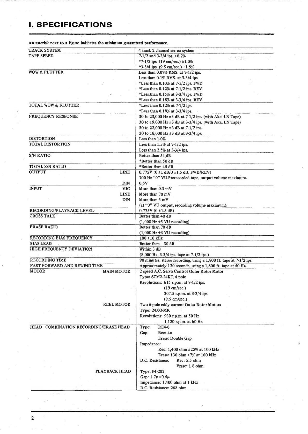
GSPECIFICATIONS
ceva
eScssGac
ts
edudoe
Ue
bak
bo
eed
ea
tau
des
tn
te
2
Il.
DISMANTLING
OF
UNIT
............
0.00
c
ccc
e
cence
cece
eee
eeeeeeeeees
4
Il.
ARRANGEMENT
OF
MAIN
PARTS
.............
0.00
cceececceceeeseeeeeeees
6
IV.
MECHANISM
ADJUSTMENT
.......0.000000
00.
ccceeecccceeeeeseeeeeeeees
7
1.
ADJUSTMENT
OF
PINCH
WHEEL
PRESSURE
............00
ccc
eeeeeceueee
7
2.
BRAKE
TENSION
ADJUSTMENT
...........0.
0.0.0
cceceeceeeeeeeeeeeues
8
3.
ADJUSTMENT
OF
REEL
TABLE
HEIGHT
................000ceeeceeseeeee
9
4,
ADJUSTMENT
OF
CAPSTAN
MOTOR
SHAFT
LOOSE
PLAY
............00000
9
5,
ADJUSTMENT
OF
IMPEDANCE
ROLLER
SHAFT
LOOSE
PLAY................
10
6.
HEIGHT
ADJUSTMENT
OF
TAPE
GUIDE
ON
TENSION
ARM
.................
10
7,
ADJUSTMENT
OF
TENSION
ARM
MICROSWITCH
SW-9
POSITION..............
11
8.
ADJUSTMENT
OF
RECORDING
SLIDE
SWITCH
(SW-10)
TIMING
...............
7
9,
ADJUSTMENT
OF
FF
MICROSWITCH
(SW-5)
ACTUATOR
POSITION
............
12
10,
ADJUSTMENT
OF
PLAY
MICROSWITCH
(SW-7
and
SW-11)
ACTIVATOR
POSITION
......
sido
eh
tene
bole
ieueaas,
ath
ee
rm
ya
NV,
“HEAD
ADIUSTMENT
95050000
92
oo
dee
dev
ose
G
ha
W
ES
Eciads
Aaa
Gemee
gloes
13
VI.
AMPLIFIER
SYSTEM
ADJUSTMENT
.
0.00000...
00.00
ccc
cece
cee
eee
cece
eeeees
15
1.
POWER
SUPPLY
VOLTAGE
ADJUSTMENT
...........
ccc
ceccececucceeeee
15
Bs
TAPE’
SPEED
ADJUSTMENT
scious
tac
sire
is.
2
dealqa
cel
Wed
cr
heed
eared
15
3.
RECORDING,
PLAYBACK
AMPLIFIER
ADJUSTMENT
.................-000-.
16
VII.
D.C.
RESISTANCE
OF
VARIOUS
COILS
........0.
0000
c
cece
cee
cece
ee
eeeees
17
VII.
CLASSIFICATION
OF
VARIOUS
P.C.
BOARDS
............
00000
cece
eeeeueeeee
17
1,
P.C.
BOARD
INTERCHANGEABILITY
CHART
..
0.0...
0.00
cee
cee
cece
eeeeee
V7
2.
COMPOSITE
VIEWS
OF
COMPONENTS
.........0..
0.000
cece
ceeeeuuceeees
18
For
basic
adjustments,
measuring
methods,
and
operating
principles,
refer
to
GENERAL
OPERATING
PRINCIPLES
AND
ADJUSTMENTS.