Alcad 9650007 MDA-300 User manual

MÓDULOS ELECTRÓNICOS
ELECTRONIC MODULES
MODULES ELECTRONIQUE
VIDEOPORTERO ELECTRÓNICO - VIDEODOOR ENTRY SYSTEMS - VIDEOPORTIER ÉLECTRONIQUE
9650007 MDA-300 Modulador III multinorma con salida DC para alimentación de
telecámara con alimentación externa
9650009 MDA-400 Modulador UHF multinorma con salida DC para alimentación de
telecámara con alimentación externa
Moduladores de TV, que a partir de una señal de ídeo generan un canal de TV analógico.
Disponen de salida DC para alimentar una telecámara con alimentación externa ALCAD.
De utilidad en instalaciones donde la placa de calle incorpora esta telecámara, permitiendo
alimentar la telecámara y modular la señal de ídeo de la misma a un canal de salida, para
posteriormente distribuir dicho canal en la instalación de TV de las i iendas.
9650007 MDA-300 Modulateur III multinorme avec sortie DC pour alimentation dune
caméra avec alimentation externe
9650009 MDA-400 Modulateur UHF multinorme avec sortie DC pour alimentation dune
caméra avec alimentation externe
Modulateurs TV, qui génèrent un canal de TV analogique à partir dun signal idéo. Ils
disposent dune sortie DC pour alimenter une caméra a ec alimentation externe ALCAD.
Utilisé dans des installations où la plaque de rue incorpore cette caméra, en permettant
lalimentation de la télécaméra et module le signal idéo de celle-ci dans canal de sortie,
pour le distribuer dans la télédistribution de la collecti e.
9650007 MDA-300 Multistandard BIII m dulat r with DC utput t feed vide unit with
external p wer supply
9650009 MDA-400 Multistandard UHF m dulat r with DC utput t feed vide unit with
external p wer supply
TV modulators which generate an analogue TV channel from a ideo signal. They include
DC output to feed a ideo unit with ALCAD external power supply unit.
They are useful in installations where the entrance panel incorporates this kind of ideo unit
since they allows power to be supplied to the camera while modulating the ideo signal from
the camera to an output channel, so that this channel can then be distributed to the TV
installation in the flats.
111 mm
70 mm
DC OUT : 15V
MODULATOR
965 SERIES
50-60Hz
230V~ ±10%
0.2 A
42 mm

VIDEOPORTERO ELECTRÓNICO - VIDEODOOR ENTRY SYSTEMS - VIDEOPORTIER ÉLECTRONIQUE
INSTRUCCIONES GENERALES DE MONTAJE Y CONEXIÓN
GENERAL INSTRUCTIONS FOR ASSEMBLY AND CONNECTION
INSTRUCTIÓN GÉNÉRALES DE MONTAGE ET CONNEXION
To ensure the best possible connection
from the coaxial cable, follow steps
1 through 4. Use the male type F
connectors pro ided.
Pour garantir une connexion
optimale du câble coaxial, sui ez
les étapes de 1 à 4. Utilisez les
connecteurs F mâle fournies
1Para garantizar una óptima
conexión del cable coaxial, siga los
pasos 1 a 4. Utilice los conectores
F macho suministrados
2Retire haciendo palanca la tapa de
protección del equipo.
Le er off the protecti e co er of the
equipment
Enle ez en faisant le ier le cou ercle
de protection de léquipement.
3Puede fijar el modulador a la pared
con los tacos y tornillos
suministrados.
The modulator can be fixed to the
wall using the wall-plugs and screws
pro ided.
Le modulateur peut être fixé au mur
grâce aux che illes et is fournies
11
2
3
4
Æ
6,5 - 6,8 mm
8±1mm3±1
12 mm
Conector F macho
Male type F connector
Connecteur F mâle
Æ
6,8 - 7,1 mm 6±1mm
6±1mm
6±1mm
11
2
3
4
2

VIDEOPORTERO ELECTRÓNICO - VIDEODOOR ENTRY SYSTEMS - VIDEOPORTIER ÉLECTRONIQUE
5Seleccione el canal de salida. Vea
selección del canal de salida.
Select the output channel. See
Selecting the Output Channel.
Choisir le canal de sortie. Voir
sélection du canal de sortie.
4Realice las conexiones eléctricas.
Vea instrucciones de conexión.
Make the electrical connections. See
Connection Instructions.
Réaliser les connexions électriques.
Voir instructions de connexion.
6Ajuste el ni el de salida del canal.
Adjust the output le el of the channel.
Réglez le ni eau de sortie du canal.
7Coloque la tapa de protección.
Replace the protecti e co er.
Refermer le cou ercle de protection.
3

4
VIDEOPORTERO ELECTRÓNICO - VIDEODOOR ENTRY SYSTEMS - VIDEOPORTIER ÉLECTRONIQUE
V1, M
+ _
Telecámara con alimentación exterior
Video unit with external power supply unit
Caméra a ec alimentation externe
Salida canal TV
TV channel output
Sortie du canal TV
SW1
INSTRUCIONES DE CONEXIÓN - CONNECTION INSTRUCTIONS - INSTRUCTIONS DE CONNEXION
ORNAS - TERMINALS - ORNES
Negro
Black
Noir
Blanco-Negro
White-Black
Blanc-Noir
_
+
Entrada señal de ídeo - Video signal input - Entrée du signal idéo
Tensión de salida DC - DC output oltage - Tension de sortie DC
Salida canal de TV - TV channel output - Sortie du canal TV

VIDEOPORTERO ELECTRÓNICO - VIDEODOOR ENTRY SYSTEMS - VIDEOPORTIER ÉLECTRONIQUE
SELECCIÓN DEL CANAL DE SALIDA
SELECTING THE OUTPUT CHANNEL
SÉLECTION DU CANAL DE SORTIE
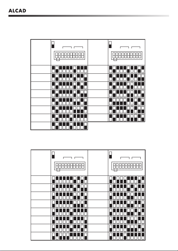
Cada modulador dispone de un switch con 10 microinterruptores que permiten definir la
norma de TV del país y el canal de salida deseado.
En las siguientes tablas se indican las normas de TV y el canal de TV de salida en función
de la posición de los 10 microinterruptores. Coloque los microinterruptores en la posición
adecuada en función de la norma de TV y del canal de salida que se desee asignar.
All modulators are equipped with a switch with 10 microswitches which are used to define
the TV standard in use in different countries as well as the desired output channel.
The following tables show the TV standards and the TV output channels which are defined
according to the positions of the 10 microswitches. Set the microswitches to the appropriate
positions to obtain the required TV standard and output channel.
Chaque modulateur possède un commutateur a ec 10 micro-interrupteurs qui permettent la
définition de la norme TV dun pays et le canal de sortie désiré.
Dans les tableaux sui ants, ous trou erez les normes de TV et le canal de sortie TV en fonction
de la position des 10 micro-interrupteurs. Placer les micro-interrupteurs dans la position
adéquate en fonction des normes de TV et canaux de sortie désirés.
Canal
Channel
Canal
5
6
7
8
9
10
11
12
S11
Canal
Channel
Canal
S12
S13
S14
S15
S16
S17
S18
S19
S20
STD
43 214321
x10 x1
CHANNEL
ON
STD
43 214321
x10 x1
CHANNEL
ON
MDA-300
Norma CCIR EUROPE
Standard B CCIR EUROPE
Norme CCIR EUROPE
5
VIDEOPORTERO ELECTRÓNICO - VIDEODOOR ENTRY SYSTEMS - VIDEOPORTIER ÉLECTRONIQUE
Canal
Channel
Canal
D
E
F
G
H
I
J
S11
Canal
Channel
Canal
S12
S13
S14
S15
S16
S17
S18
STD
43214321
x10 x1
CHANNEL
ON
STD
43214321
x10 x1
CHANNEL
ON
Canal
Channel
Canal
6
7
8
9
10
11
12
S11
Canal
Channel
Canal
S12
S13
S14
S15
S16
S17
S18
S20
STD
43 214321
x10 x1
CHANNEL
ON
STD
43 214321
x10 x1
CHANNEL
ON
Norma I IRELAND
Standard I IRELAND
Norme I IRELAND
Norma D OIRT
Standard D OIRT
Norme D OIRT
6

VIDEOPORTERO ELECTRÓNICO - VIDEODOOR ENTRY SYSTEMS - VIDEOPORTIER ÉLECTRONIQUE
Canal
Channel
Canal
D
E
F
G
H
H1
H2
S11
Canal
Channel
Canal
S13
S14
S15
S16
S17
S18
S19
S20
S12
STD
43214321
x10 x1
CHANNEL
ON
STD
43214321
x10 x1
CHANNEL
ON
Norma ITALY
Standard B ITALY
Norme ITALY
Norma I SOUTH AFRICA
Standard I SOUTH AFRICA
Norme I SOUTH AFRICA
Canal
Channel
Canal
4
5
6
7
8
9
10
Canal
Channel
Canal
12
S14
S15
S16
S17
S18
STD
43214321
x10 x1
CHANNEL
ON
STD
43214321
x10 x1
CHANNEL
ON
7

VIDEOPORTERO ELECTRÓNICO - VIDEODOOR ENTRY SYSTEMS - VIDEOPORTIER ÉLECTRONIQUE
Canal
Channel
Canal
6
7
8
9
10
11
12
S9
Canal
Channel
Canal
S10
S11
S12
S13
S14
S15
S16
S17
STD
43 214321
x10 x1
CHANNEL
ON
STD
43 214321
x10 x1
CHANNEL
ON
Norma D POLAND
Standard D POLAND
Norme D POLAND
8

VIDEOPORTERO ELECTRÓNICO - VIDEODOOR ENTRY SYSTEMS - VIDEOPORTIER ÉLECTRONIQUE
Norma
Standard
Norme
G CCIR
G ITALY
I UK
Norma
Standard
Norme
I SOUTH AFRICA
K OIRT
STD
43214321
x10 x1
CHANNEL
ON
STD
43214321
x10 x1
CHANNEL
ON
D POLAND
I IRELAND L FRANCE
Canal
Channel
Canal
21
22
23
24
25
26
27
28
29
30
Canal
Channel
Canal
46
47
48
49
50
51
52
53
54
55
STD
43 214321
x10 x1
CHANNEL
ON
STD
43 214321
x10 x1
CHANNEL
ON
MDA-400
TA LA DE NORMAS
TABLE SHOWING STANDARDS
TA LEAU DE NORMES
TA LA DE CANALES
TABLE SHOWING CHANNELS
TA LEAU DE CANAUX
9

VIDEOPORTERO ELECTRÓNICO - VIDEODOOR ENTRY SYSTEMS - VIDEOPORTIER ÉLECTRONIQUE
Canal
Channel
Canal
Canal
Channel
Canal
31
32
33
34
35
36
37
38
39
40
41
42
43
44
45
56
57
58
59
60
61
62
63
64
65
66
67
68
69
STD
43 214321
x10 x1
CHANNEL
ON
STD
43214321
x10 x1
CHANNEL
ON
10
This manual suits for next models
1
Table of contents
Other Alcad Control Unit manuals


Popular Control Unit manuals by other brands

Festo
Festo Compact Performance CP-FB6-E Brief description

Elo TouchSystems
Elo TouchSystems DMS-SA19P-EXTME Quick installation guide

JS Automation
JS Automation MPC3034A user manual

JAUDT
JAUDT SW GII 6406 Series Translation of the original operating instructions

Spektrum
Spektrum Air Module System manual

BOC Edwards
BOC Edwards Q Series instruction manual

KHADAS
KHADAS BT Magic quick start

Etherma
Etherma eNEXHO-IL Assembly and operating instructions

PMFoundations
PMFoundations Attenuverter Assembly guide

GEA
GEA VARIVENT Operating instruction

Walther Systemtechnik
Walther Systemtechnik VMS-05 Assembly instructions

Altronix
Altronix LINQ8PD Installation and programming manual


