ALFAMATIC CSQ-Visual User manual

Issue 2 - February 8, 2017
CSQ – Visual
User manual
Version 2 and subsequent versions

2

3
1 General information .............................................................................................................5
1.1
The check theory ....................................................................................................................... 5
1.2
Instrument capacity................................................................................................................... 5
1.3
Operating principles of the instrument ..................................................................................... 5
2 Installing CSQ- isual...........................................................................................................8
3 How to start ..........................................................................................................................
3.1
The CSQ - isual keyboard....................................................................................................... 9
3.2
Setting up the display .............................................................................................................. 10
3.3
First approach ........................................................................................................................ 10
3.4
Using the menus...................................................................................................................... 10
3.5
The main menu........................................................................................................................ 11
4 Works .................................................................................................................................13
4.1
Creating a new work............................................................................................................... 13
4.2
Selecting a work...................................................................................................................... 13
4.3
Changing the work name ........................................................................................................ 14
4.4
Copying a work....................................................................................................................... 14
4.5
Eliminating a work.................................................................................................................. 14
4.6
Changing a work..................................................................................................................... 14
4.7
Management of automatic work selection............................................................................... 15
4.8
The graph................................................................................................................................ 15
4.9
Work options ........................................................................................................................... 16
4.10
Phase management ................................................................................................................. 16
4.11
Channel management.............................................................................................................. 17
4.12
Auto-Check.............................................................................................................................. 17
4.13
Supplementary check management ......................................................................................... 17
5 Parameters ..........................................................................................................................1
5.1
Stop values .............................................................................................................................. 19
5.2
Limits and thresholds.............................................................................................................. 21
5.3
Work options ........................................................................................................................... 22
6 The tolerance band .............................................................................................................23
6.1
Creating the band.................................................................................................................... 23
6.2
Changing the band.................................................................................................................. 23
6.3
Eliminating the band............................................................................................................... 24
7 Reject piece ........................................................................................................................25
7.1
Reject causes........................................................................................................................... 25
7.2
Reject management ................................................................................................................. 26
8 Values measured.................................................................................................................27
8.1
The window of the values measured........................................................................................ 27
8.2
Analysis cursor........................................................................................................................ 28
Configuration of the instrument “The tools menu”............................................................2
9.1
Display management............................................................................................................... 29
9.2
Preset position ........................................................................................................................ 30
9.3
Instrument configuration......................................................................................................... 30
9.4
The Machine type menu .......................................................................................................... 31
9.5
Configuring the supplementary check..................................................................................... 33
9.6
Diagnosis ................................................................................................................................ 34
9.7
Firmware version.................................................................................................................... 34
10 Password.............................................................................................................................35
10.1
User management ................................................................................................................... 35
4
11 Calibration..........................................................................................................................36
11.1
Force transducer calibration.................................................................................................. 36
11.2
Position transducer calibration .............................................................................................. 36
11.3
Encoder alignment .................................................................................................................. 37
12 Connection to the computer ...............................................................................................3
12.1
USB connection....................................................................................................................... 39
12.2
RS232 serial port connection.................................................................................................. 42
12.3
Ethernet connection ................................................................................................................ 42
13 Technical data and problem-solving ..................................................................................45
13.1
Problem-solving...................................................................................................................... 45
13.2
The instrument does not communication trough the USB port ............................................... 45
13.3
The instrument does not communication trough the RS232 port............................................ 45
13.4
The instrument does not communication trough the Ethernet port......................................... 45
13.5
The empty force is not zero ..................................................................................................... 45
13.6
Messages ................................................................................................................................. 46

5
1 General information
CSQ- isual is a measuring instrument which, when connected to a press, guarantees the quality
control of production processes.
Interfaced with a position transducer and a load cell, it continuously measures the position and
instant force. The containment of the force-position curve inside a suitably positioned continuous
band of tolerance has been ascertained. An additional check sensor known as a extra control can be
connected to the CSQ- isual.
It is possible to connect the CSQ- isual to a computer to store all the curves measured and the
settings. For this purpose, please refer to the specific WinScope software manual.
1.1 The check theory
When processing a sample piece, the data related to the position of the cylinder and the force
exercised by it is recorded and the force-position graph characteristic to the process performed can
be traced.
If several processes are performed on similar pieces, the respective force-position curves will also
be similar. If, on the other hand, one of the pieces to be processed is different from the sample, the
relative curve will also be different from the sample. The way in which the check of the curve can
guarantee constant processing quality is intuitive.
1.2 Instrument capacity
The CSQ- isual works on a continuous tollerance band, controlling the whole force-position curve.
It controls the position and force values attained. It controls the stoppage of the press upon reaching
a position or force. It enables the management of several different phases for each type of process.
All these setting are memorised on works.
The power for the valves, warning lights, tranducers and end limits is supplied by the instrument.
It is possible to connect the CSQ- isual to the computer and, thanks to the WinScope program, save
the curves, change the settings or print them.
1.3 perating principles of the instrument
The position of the cylinder is usually detected by a position transducer fastened to the strut of the
press.
1.3.1 Absolute and relative positions
The positions referred to the transducer zero are called absolute positions. The positions referred to
the start of work are called relative positions. The CSQ- isual can use both absolute and relative
positions. To detect the start position of the work, use the load cell: when the force measured by the
load cell exceeds a programmed value the zero of the relative positions is set. This force value is
called the start force. The start position can be controlled with two limits, minimum and maximum
(chapter 5.2).

6
1 Upper dead point
2 Absolute position zero
3 Relative position zero
Figure 1
The precision of the zero detected measuring the force cannot be high. It depends on the speed of
the cylinder and, above all, on the type of piece to be processed. During the fitting operations, the
two pieces have rounded corners, so the initial position varied with the variation in the rounding and
the force used to position one piece inside the other.
1.3.2 Check of the force-movement values
The CSQ- isual has different functions. The curve is controlled suing a tolerance band (chapter 6)
and limits (chapter 5.2). The limits are: minimum and maximum force and minimum and maximum
position; they can be set or disabled and check the maximum value reached during the test. If the
maximum position reached does not exceed the minimum position and/or exceeds the maximum,
the piece is rejected. In the same way, if the maximum position reached does not exceed the
minimum force and/or exceeds the maximum, the piece is rejected. From the theoretic viewpoint
there is an ideal curve which is obtained by machining perfect pieces (in practice there can be a
sample curve obtained by machining carefully selected pieces). If there are any geometric
tolerances or differences in material these will differ from the ideal curve. In practice there is a
tolerance band around the sample curve which means, if the curve obtained by the current
machining process does not pass through this band, the piece is rejected (due to the definitions and
programming of the tolerance band). The piece is only good if the check of the minimum and
maximum limits and the check using the tolerance band are successful. The CSQ- isual also
controls the return of the cylinder upon completion of the machining process. This return can take
place if a certain force (stop force) or a determined position (stop position) is reached. It is possible
to simultaneously set the two force and position values. In this case the first value to be reached will
trigger the return of the cylinder. Changing the configuration value it is also possible to check the

7
return of the cylinder when the curve moves outside the tolerance band. It is always possible to
trigger the return of the unit by pressing the button on the keyboard (stopping the operation).

8
2 Installing CSQ-Visual
Consult the installation manual.

3 How to start
This chapter teaches the user how to perform basic operations for programming and using the CSQ-
isual.
To better explain the operations, we recommend practical tests; to do this it is very useful to have an
adequately supple elastic support to simulate repeated machining.
Figure 16
There is a button on the back to switch the instrument on. When it is pressed, the display lights up
and, after few seconds, this graph appear:
Figure 18
3.1 The CSQ - Visual keyboard
Press the button at the bottom of the display to display a rectangle split into four, containing
the items that make up the main menu; the title of the menu is printed above this rectangle. To
select an item from the menus it is necessary to press the corresponding button below it .
The button stops the press, cancels the operations and enables the return to the menu above;
constant pressure for a few seconds enables the return to the initial display.
The button is used to confirm the values to be entered when requested. During the construction
of the tolerance band it enables the entry of the position of the active point.
The button enables the cancellation of any entry errors. If the menu is not displayed, this button
enables the display of the cursor.

10
During the construction of the tolerance band, the buttons enable the movement of
the active point. When the cursor is visible it can be moved using the buttons.
3.2 Setting up the display
The picture may be too light or too dark. To improve vision it is possible to increase or decrease the
contrast of the display using the commands in the
TOOLS > DISPLAY MANAGEMENT
menu.
At the top of the display there are three fields which can display different types of information. To
choose what to display in these fields, select the
TOOLS > DISPLAY MANAGEMENT
menu
(paragraph 0).
The central part of the display is occupied by the force-position graph. It is possible to change the
end scale values using the commands in the
CHANGE WORK > GRAPH SETUP
menu (paragraph 0).
3.3 First approach
After the CSQ- isual has been switched on, it is necessary first of all to create a new work: press
the button, press the button under the
WORKS MANAGEMENT
item and press the button
under
CREATE NEW WORK
. Now enter, if required, the name of the wok and press the button.
After creating the work, tell the instrument when to stop the press, entering a stop value: press the
button under
EDIT WORK
, press the button under
CHANGE WORK
, press the button under
PARAMETERS
, press the button under
STOP VALUES
, press the button under
STOP FORCE
(because force and not position is explained in the chapter 5), and enter a value lower than the
maximum force which the press can exercise and press . Lastly, return to the initial display
pressing the button for a few seconds.
Giving the machine start command, the press will exercise a force which increases to the stop value
inserted earlier.
If an excessively high stop force is entered, the press continues working and it is necessary to press
the to make it return. In this case, the piece is rejected as the work has been interrupted and it
is necessary to proceed as indicated in chapter 6.
If the settings of the graph allow, the curve will appear, otherwise the origin and the end scale must
be changed as described in paragraph 0.
Chapter 4 presents a detailed explanation of how to create a useful work.
Note: in the rest of this manual, where you are instructed, for example, to select the
WORK
MANAGEMENT > CREATE NEW WORK
command, you must press the button and then press
the button under
WORK MANAGEMENT
and, lastly, press the button under
CREATE NEW
WORK
.
3.4 Using the menus
Press the button at the bottom of the display to display a rectangle split into four, containing
the items that make up the main menu; the title of the menu is printed above this rectangle. To
select an item from the menus it is necessary to press the corresponding button below it .
The button enables the return to the menu above; constant pressure for a few seconds enables
the return to the initial display.

11
When a menu is displayed or when entering a value, by keeping the button pressed
continuously, it is possible to momentarily see the graph and the curve.
When the button is pressed to display the main menu, button 8 can be pressed to change
language. Furthermore, if several load cells are connected to the instrument, it is possible, pressing
buttons 1 to 6, to hide the curves for the single load cells which will remain active.
When a manual press is connected to the instrument, if the T.D.C. is freed, when the lever is
activated the menu is automatically hidden.
3.5 The main menu
The main menu is the first to be displayed using the button.
When the main menu is visible the buttons have special functions, as described in paragraph 0.
The first item on the menu is
WORKS MANAGEMENT
. This item enables the creation and choice of
works. It also enables the alteration of work parameters, work options and the band. See chapter 4.
The second item on the main menu is
DISPLAY MEASURED VALUES
. When this command is
selected, the window summarising the values measured in the last acquisition is shown. See chapter
8.
The third item is different depending on the configuration of the instrument.
CHANGE WORK
This is a shortcut which leads to the submenu for changing the current work.
PHASES MANAGEMENT
This is another shortcut which leads to the submenu for changing the phases of the current
work.
PIECE CODE
This item enables the entry of the code of the piece we are about to machine.
ZERO PIECE COUNTER
By selecting this item and confirming it, the counters of the pieces of the work being used are
zeroed.
The fourth item of the main menu is
TOOLS
. Using this menu it is possible to change the appearance
of the display or change the configuration of the instrument. See chapter .
3.5.1 The special functions of the buttons in the main menu
If the menus are not displayed, press the button to display the main menu together with the
windows that show the special function of the buttons.
Figure 2

12
CURSOR
With the button it is possible to display the cursor to measure the force in a determined
point of the curve (chapter 0).
LANGUAGE
Button 8 allows you to change the language used by the instrument. Two languages are
available and are loaded with the CSQ Visual Setup software.
CHANNELS
Buttons 1 to 6 allow the choie of whether to show or hide the curves of the single channels
when there are moe than one (chapter 0). The window in the top right-hand corner shows all the
channels present and a black hyphen is drawn above each one to indicate that the channel is
displayed. In it is possible to see the status of the two channels of a CSQ-Visual with the two
force transducers connected: the curve of channel 1 is not visible, while the curve of channel 2
is visible. Even when the curve of a channel is not displayed, this will be controlled anyway.

Issue 2 - February 8, 2017
4 Works
The CSQ- isual memorises all the settings (parameters, band and counters) in a block of the
internal memory. It can memorise several blocks which can be assigned different names. Every
block can be used for a different work. Every block is called Work.
The main menu includes an item called
WORKS MANAGEMENT
. Using this submenu it is possible to
create a new work, choose an existing work, changing the work being used or eliminate it.
If a work is present, the
WORKS MANAGEMENT
submenu will have four items (Figure 3
).
Figure 3
If the automatic work selection is active, to choose a work other than that selected automatically the
unlock password in required.
4.1 Creating a new work
To create a new work (a block in the instrument’s memory) use the
WORKS MANAGEMENT > CREATE
NEW WORK
command and assign it a name; if the automatic work selection is active, see chapter 0.
The name may be the drawing number, the customer’s name or whatever you prefer to identify it
easily. If a name is not entered, the work will be automatically named as follows: Work 1, Work 2,
Work 3, etc.
Figure 4
When a new work is created, the new name is requested and then, if a work was already being used,
you will be asked if you wish to copy it. If you decide not to copy the work being used, the new one
will be empty.
After creating the work, the parameters have to be set up, the options set up and the band built.
4.2 Selecting a work
The
WORKS MANAGEMENT
menu contains the command
CHANGE WORK
. When this command is
selected, the list of works present is displayed (Figure 5

14
). If the clock is present, the date and time of the last work change are shown alongside the
name. It is possible to choose a work using the buttons and pressing .
Figure 5
If the list is very long, it is possible to press the numeric buttons to jump from one point to another
in the list.
4.3 Changing the work name
To change the name of a work it is necessary first of all to select it as indicated in paragraph 0.
After selecting the work with the name to be changed, you have to redisplay the list of works
present, using the
WORKS MANAGEMENT > CHANGE WORK
command and, with the black selection line
in the work chosen, press the button. The name input window will appear.
4.4 Copying a work
To copy a work it is necessary first of all to select the work to be copied as indicated in paragraph 0.
After selecting the work to be copied, it is necessary to create the new work using the
WORKS
MANAGEMENT > CREATE NEW WORK
command and, when asked whether you wish to copy the work,
answer YES with the button below.
4.5 Eliminating a work
The
WORKS MANAGEMENT
menu contains the command
DELETE WORK
. This command enables the
permanent elimination of the work being used. When you wish to eliminate a work, confirmation is
required.
4.6 Changing a work
The
EDIT WORK
menu enables the alteration of all the work parameters.
To change the name of a work, see paragraph 0.
In the works the parameters set to zero will be ignored by the instrument.
These are the items of the
EDIT WORK
menu:
CHANGE WORK
This menu contains the items used to change the parameters, options and band of the work; this
item is also usually present in the main menu. To set the work parameters see chapter 4. If the
work comprises several phases, this item is replaced by
PHASE MANAGEMENT
.
PHASE MANAGEMENT
This menu enables the choice of the phase to be changed before accessing the change of the
parameters. Furthermore, if the instrument is configured in this sense, it is possible to select
whether to exclude a phase and if so which one (paragraph 0).

15
PIECE COUNTER
In this menu it is possible to zero the piece counter and choose a maximum number of rejected
pieces after which to block the instrument. To unlock the instrument the unlock password is
required.
AUTO-CHECK
This menu enables the management of the Auto-Check function.
4.7 Management of automatic work selection
When the automatic work selection is active, the CSQ-Visual holds all the selectable works in the
memory. These works are initially empty. To make an empty work suitable for use, it is necessary
to enter the
WORKS MANAGEMENT > CHANGE WORK
menu and press enter on the work required, then
it will be possible to choose the name of the work and, if a work is in use, it will be possible to copy
it.
It is possible to create additional works using the unlock password.
It is possible to select a different work from that selected automatically using the unlock password.
4.8 The graph
The
CHANGE WORK
menu contains the
GRAPH SETUP
item which enables changes to the axes of the
graph. It is not possible to change these values and make the band completely or partially invisible.
Figure 6
Figure 7
As shown in the two figures above, it is possible to choose the following values:
GRAPH ORIGIN
This is the original value of the horizontal axis of the positions. This parameter makes it
possible to hide the whole stroke which is of no interest, such as the approach stroke. If the
relative positions are used, the origin is usually set to zero.
END SCALE POSITION
The end scale of the positions indicates the stroke shown in the graph. The end scale can be
selected from a list.
If, for instance, an end scale of 20 mm is chosen and the origin is set at 33 mm, the graph will
show the whole stroke from 33 mm to 53 mm.
END SCALE FORCE
The end scale of the forces indicates the maximum force shown in the graph. The end scale can
be selected from a list.
4.8.1 How to set up the graph
After machining a piece it is possible to display the values measured (chapter 8). These can be used
to obtain the axes of the graph.
As graph origin, enter a value slightly lower than the start position measured. As end scale of the
positions, enter the value which, added to the position origin entered, is higher than the position
reached measured.
As force end scale, choose the value higher than the force reached measured.

16
4.9 Work options
In the work, besides the general options, there are options for the management of rejects and options
for supplementary check. The options can be accessed from the
CHANGE WORK > OPTIONS AND
OTHER CHECKS
menu, which contains the following items:
REJECT MANAGEMENT
Enables the definition of the behaviour and class for every type of reject.
OPTIONS
The general work options can be set here
CHANNEL EXCLUSION
This item enables the exclusion of one or more channels (load cells) when present.
SUPPLEMENTARY CHECK MANAGEMENT
This command enables access to the supplementary check management menu, if present.
The general work options are listed below:
USE RELATIVE POSITIONS
By activating this option, relative positions are used in place of absolute positions..
4.10 Phase management
The CSQ- isual can be configured for the management of several phases in the same work.
The phase to be performed is chosen either in sequence or by an external controller (PLC). In the
first case it is possible to decide whether or not to perform each single phase.
Figure 8
The phase management menu (Figure 8
) contains the following items:
SELECT PHASE TO EDIT
This enables the choice of the phase to be changed or displayed; the phase performed will be
that envisaged. It is possible to change the phase to be changed or displayed using the
buttons when the menus are not visible.
ENA LE PHASES
This command enables the choice of the phases to be carried out.
EDIT PHASE
This is used to change the current phase.
SELECT PHASE TO EXECUTE
This command is used to carry out a phase out of sequence. To carry out a phase out of
sequence it is necessary to know the unlock password.
4.10.1 Confirm reject
It is possible to configure the instrument so that when a phase gives a reject result, confirmation is
requested (Figure

17
). In this case, if the operator confirms the result, the piece is counted as a reject and the instrument
prepares for the first phase of a new piece; if the result is not conformed, the phase can be repeated.
Figure
To activate the reject confirmation request function it is necessary to change the Automatic code
selection as indicated in paragraph 0.
4.11 Channel management
It is possible to connect up to six force transducers to the CSQ- isual to check the same number of
force-movement curves. While every force transducer measures the force of a channel, there is only
one position transducer for all the channels. It is possible to exclude one or more channels from the
check thanks to the
CHANGE WORK > OPTIONS AND OTHER CHECKS > CHANNEL EXCLUSION
menu.
The force of one channel at a time is shown under the graph, using the numeric buttons from 1 to 6,
when the menus are not displayed, it is possible to display the current force of every single channel.
To display the curve of certain channels it is necessary to press the button to display the main
menu. In this way the status of the channels displayed is shown in a rectangle in the top right-hand
corner, followed by a numeric button from 1 to 6.
4.12 Auto-Check
The Auto-Check function is managed by the CSQ- isual as follows: Every time the instrument is
switched on, or every N1 pieces machines, N2 sample pieces must be machined.
Figure 10
It is possible to decide how many pieces to machine between each Auto-Check. If zero is entered,
the Auto-Check function is excluded.
It is possible to decide how many sample to machine.
It is possible to decide whether to block the instrument if a good sample gives a reject result or vice
versa.
4.13 Supplementary check management
The CSQ- isual can perform an additional check, in addition to the force and position check, to
establish whether the piece is good or a reject.

18
In the
EDIT WORK > CHANGE WORK > OPTIONS AND OTHER CHECKS > SUPPLEMENTARY CHECK
MANAGEMENT
menu, it is possible to establish when and how to perform the supplementary check.
The items of this menu are described below:
MEASUREMENT POSITION
This is used to change the position used for the supplementary check. See the options in the next
paragraph.
CHECK
This command enables the activation of the actuator linked to the supplementary check, where
present. In this way it is possible to check the operation and make any necessary adjustments.
OPTIONS
The options determine when to carry out the supplementary check as described in the next
paragraph.
4.13.1 Supplementary check options
The supplementary check options are:
DO NOT CARRY OUT THE SUPPLEMENTARY MEASUREMENT
The supplementary measurement is not carried out.
MEASURE AT START
The supplementary check is carried out when the instrument receives the STA T command.
MEASURE AT STOP
The supplementary check is carried out when the instrument wishes to give the stop command
and the piece is good.
MEASURE AT END
The supplementary check is carried out when the press is withdrawn.
MEASURE AT A POSITION
The supplementary check is carried out at a position established with the
MEASUREMENT
POSITION
of the
SUPPLEMENTARY CHECK MANAGEMENT.
MEASURE STARTING FROM A POSITION
The supplementary check is carried out starting at a position established with the
MEASUREMENT
POSITION
parameter of the
SUPPLEMENTARY CHECK MANAGEMENT
until the work is completed.
MEASURE UP TO A POSITION
The supplementary check is carried out from when the instrument receives the STA T
command up to a position established with the
MEASUREMENT POSITION
parameter of the
SUPPLEMENTARY CHECK MANAGEMENT
.
MEASURE DURING
The supplementary check is carried out during the whole work process.

1
5 Parameters
In the works the parameters set to zero will be ignored by the instrument.
5.1 Stop values
After creating a new work, the first thing to do is tell the instrument when to stop the press. To set
the stop values, use the
EDIT WORK > CHANGE WORK > PARAMETERS > STOP VALUES
command.
The CSQ- isual can stop the press when the force reaches a determined value (stop force) or when
the press reaches a determined position (Stop position).
1 Stop Force
2 Stop Position
Figure 11
The press is also stopped when the maximum acquisition time is up. It is possible to increase the
maximum acquisition time using the CSQ- isual Setup software.
5.1.1 Notes on stop values
A stop value set to zero is not used.
When both the stop force and stop position are set, the stop will be commanded if either is
exceeded.
If the stop values are not indicated (or are not reached by the curve) it is necessary to press to
bring the unit back.
It is normal to observe values reached higher than the stop values; this is due to the delayed
intervention of the electromechanical parts.
It is possible to keep the press working upon reaching the stop values for a preset time. To set the
press stop delay time, use the
EDIT WORK > CHANGE WORK > PARAMETERS > STOP VALUES
>
STOP DELAY
command.
5.1.2 How to choose the stop values
The stop must be set up differently depending on the type of work. There are three different types of
work:
1) Complete fitting, caulking or work up to a mechanical contact.
2) Work up to a position (without mechanical contacts).
3) Flexion and breakage text.
5.1.2.1 Stop with mechanical contact.
In most cases the press is used to perform a stroke up to a mechanical contact. In this case the curve
will be similar to that in Figure 12

20
i.e.: the force will be zero for the whole approach stroke then, when it reaches the piece (at the start
position) the force will begin to increase until the mechanical contact is reached, where it will
increase up to the maximum force of the press (vertical part of the curve).
Figure 12
In this case the stop force must be used, inasmuch as the force will always reach the maximum that
can be exercised by the press. If we were to use the stop position, this might not be reached if the
piece were to be slightly higher than expected or could be reached before completion of the work if
the piece were to be too low.
The stop force must be chosen to guarantee the completion of the work.
The stop force must be less than the breakage force of the piece or, even worse, of the instrument.
The stop force must be less than the maximum force that the press can exercise.
5.1.2.2 Stop without mechanical contact.
It is possible to stop the descent of the press stalk in a set position by establishing the stop position.
In this case the instrument will switch the valve which controls the descent of the press as soon as
the stop position is reached. This valve will take some time to switch and more time will be
required before it starts to evacuate the pressurised air in the cylinder: for these reasons the real stop
of the press will be in a higher position than the stop position set. The higher the descent the greater
the error and the greater the difference between the force needed to do the job and the force of the
cylinder.
5.1.2.3 Stop during a flexion and breakage test
The force the piece under examination must withstand must be used as the stop force. In the case of
breakage, the stop force will not be reached, so it is also necessary to set the stop position at a value
which cannot be reached without the breakage of the piece.
If the piece resists the stop force (Figure 13
), after the test, the maximum position measured by the CSQ- isual will be equivalent to the flexion
to which the piece has been subject.
Figure 13
If the piece breaks before the stop force is reached (Figure 14
Other manuals for CSQ-Visual
2
Table of contents
Other ALFAMATIC Measuring Instrument manuals

ALFAMATIC
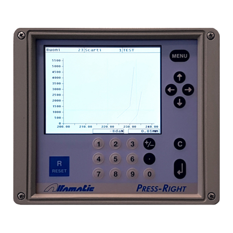
ALFAMATIC Press-Right User manual

ALFAMATIC
ALFAMATIC CSQ-Visual User manual

ALFAMATIC
ALFAMATIC PRESS -RIGHT User manual

ALFAMATIC
ALFAMATIC Press-Right User manual

ALFAMATIC
ALFAMATIC Press-Right User manual

ALFAMATIC
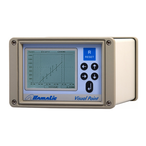
ALFAMATIC Visual Point User manual

ALFAMATIC
ALFAMATIC CSQVIO8 User manual

ALFAMATIC
ALFAMATIC Press-Right User manual
Popular Measuring Instrument manuals by other brands

Taik
Taik T250 instruction manual

Urrea
Urrea SURTEK 122230 User manual and warranty

Endress+Hauser
Endress+Hauser RID14 Brief operating instructions

Minebea Intec
Minebea Intec Puro operating instructions

Extech Instruments
Extech Instruments 480846 user guide

Hanna Instruments
Hanna Instruments HI 9142 instruction manual