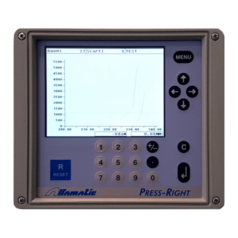
ALFAMATIC Press-Right User manual

U S E R M A N U A L
PRESS-RIGHT
FOR ELECTRIC PRESS
•User manual


1General information .............................................................................................. 5
1.1 Notes on control theory.............................................................................................5
1.2 Pressing cycle...........................................................................................................5
1.3 Absolute and relative positions..................................................................................6
1.4 Control of position-force curve...................................................................................7
2Installation of Press-Right..................................................................................... 9
3Getting started.................................................................................................... 10
3.1 The keyboard of Press-Right...................................................................................10
3.2 First approach.........................................................................................................10
3.3 Create a job ............................................................................................................10
3.4 Set the movement...................................................................................................11
3.5 Set the view ............................................................................................................11
3.6 The main menu.......................................................................................................11
4The JOB.............................................................................................................. 13
4.1 Create a new job.....................................................................................................13
4.2 Selecting a job ........................................................................................................13
4.3 Change the name of the job....................................................................................13
4.4 Copy a job...............................................................................................................13
4.5 Delete a job.............................................................................................................13
4.6 Edit a job.................................................................................................................13
4.7 Job counters ...........................................................................................................14
4.8 Managing the automatic selection of jobs as an external user.................................14
4.9 The graph ...............................................................................................................14
4.10 Rejected options and management.........................................................................14
4.11 Phases management..............................................................................................14
4.12 Channel management.............................................................................................15
4.13 Self-verification .......................................................................................................15
4.14 Managing additional controls...................................................................................15
5Parameters......................................................................................................... 17
5.1 Motion management ...............................................................................................17
5.2 Limits and thresholds..............................................................................................17
5.3 Check points...........................................................................................................19
5.4 Job options..............................................................................................................19
6The tolerance bande........................................................................................... 21
6.1 Create the bande ....................................................................................................21
6.2 Delete the range .....................................................................................................21
7Rejected piece.................................................................................................... 22
7.1 Causes rejection .....................................................................................................22
7.2 Rejected management............................................................................................23
8The Tools menu.................................................................................................. 24
8.1 Display options........................................................................................................24
8.2 Counters and self-verification..................................................................................24
8.3 Manual moving........................................................................................................24
9Intrument configuration....................................................................................... 26
9.1 General options.......................................................................................................26
9.2 Automatic selection of jobs......................................................................................27
9.3 Phase repetetion.....................................................................................................27
10 Diagnosis............................................................................................................ 28
10.1 Firmware version.....................................................................................................28
11 Special configurations......................................................................................... 29
11.1 Additional force transducer......................................................................................29
11.2 Tool recognition ......................................................................................................29
12 Password............................................................................................................ 30
13 Computer connection.......................................................................................... 31
13.1 Connection via USB port.........................................................................................31
13.3 Connection via LAN port (Ethernet).........................................................................31
14 Field bus............................................................................................................. 33
14.1 Organization............................................................................................................33
14.2 Status and Control ..................................................................................................33
14.3 PROFINET and EtherNet/IP....................................................................................33
15 Organization of registers..................................................................................... 36
15.1 Command execution...............................................................................................36
15.2 Behavior of the status register.................................................................................36
15.3 Strings.....................................................................................................................36
15.4 Logs table...............................................................................................................37
15.5 Description of Check Point registers........................................................................43
16 Specifications and troubleshooting ..................................................................... 45
16.1 Troubleshooting......................................................................................................45
16.2 The instrument does not communicate via the USB port.........................................45
16.3 The instrument does not communicate via LAN (ethernet) port...............................45
16.4 Technical data.........................................................................................................45
16.5 Characteristics of the instrument.............................................................................45

1 General information
Press-Right is a monitor and measuring device that is connected to a press and monitors
the quality of productive processes.
Being interfaced with a displacement transducer and a load cell, it continuously monitors
its positions and instantaneous force.
1.1 Notes on control theory
During sample production, the data regarding cylinder position and the force exerted by it
are entered; the following graph may be created: position-force representing production.
If several runs are performed on similar pieces, their position-force curves will also be
similar. On the other hand, if one of the manufactured pieces is different from the sample,
its curve will be different from the sample. It is clear that monitoring the curve may affect
the quality of manufacturing.
1.2 Pressing cycle
Each pressing cycle can be divided into different moments:
1. Approach
2. Contact
3. Work
4. Pre-arrest
5. Wait
6. Return
During the approach, the cylinder advances to the End approach position.
Once the approach is finished, the cylinder advances at the Contact speed until it
comes into contact with the piece.
During the work the cylinder advances at the Working speed until the stop value is
reached. When the stop value is reached, the cylinder is stopped and a timer is started for
the set time with Waiting before return. After the time has elapsed, the return of the
cylinder is commanded with the Return speed.
1.2.1 Approach
During the approach, the cylinder advances to the End approach position. The
approach takes place with the Approach speed. During the approach, the measured
force must be less than the Collision force alarm configuration value.
If you do not want to carry out the approach, you must set the end of approach position to
zero.
1.2.2 Contact
Once the approach is finished, the cylinder advances at the Contact speed until it
comes into contact with the piece. Contact with the workpiece is detected when the
measured force exceeds the Force for contact detection control limit. If you do
not want to perform the controlled support on the piece, you must set the Contact
speed to zero.

1.2.3 Work
The work can be performed in two ways depending on whether the pre-stop is used or not.
The work without pre-stop is performed when the Pre-stop position is equal to zero.
Work without pre-stop
During work without pre-stop the cylinder advances at the Working speed until the stop
value is reached. Once the stop value has been reached, the cylinder is stopped.
Work with pre-stop
During work with pre-stop the cylinder advances at the working speed until the Pre-stop
position is reached. Once the Pre-stop value has been exceeded, the cylinder
advances up to the stop value, correcting the speed according to the distance from the
stop value. The greater the distance from the stop value the greater the speed of
movement. If the stop value is less than the actual value the speed will be negative and
the cylinder will retract to maintain the programmed stop value. The maximum speed
during pre-stop can be set with the Pre-stop speed parameter.
1.2.4 Waiting before return
When the stop value is reached, a timer is started for the set time with Waiting before
return. After the time has elapsed, the cylinder return is commanded. Of course, the
Waiting before return can be set to zero.
1.2.5 Return
After the set wait, the cylinder returns to the Rest position with the Return speed.
1.3 Absolute and relative positions
The positions referred to the cylinder zero point are referred to as absolute positions. The
positions referred to the contact point on the manufactured piece are referred to as relative
positions. Press-Right may set both the absolute and the relative positions. In order to
measure the contact point on the manufactured piece, Press-Right use the force
transducer: when the force measured exceeds the Force for contact detection
value, the relative zero point is set. This “zero point”is called conctact position. The
conctact position may be monitored by using two limits, a minimum and a maximum value
(Chapter 0).

Cylinder absolute zero point
Return position (rest position)
Relative zero point (contact position)
Figure 1
The accuracy of the conctact position measured with the load cell may not be increased. It
depends on the cylinder speed and, in particular, on the type of piece to be manufactured.
During the shrink-fitting operations, the two pieces show chamfered edges; as a result, the
conctact position varies also based on the chamfer and the force used to position a piece
into the other.
1.4 Control of position-force curve
Press-Right enjoys different functions. The curve monitoring is performed by a tolerance
range (chapter 6) and its limits (chapter 0). The limits are the following: minimum and
maximum force, minimum and maximum position; they can be set or excluded and they
monitor the maximum value obtained during the production. If the position reached does
not exceed the minimum position and/or exceeds the maximum position, the piece is
rejected. At the same time, if the maximum force reached does not exceed the minimum
force and/or does exceed the maximum force, the piece is rejected.
From a theoretical point of view there is an ideal curve that may be obtained by
manufacturing perfect pieces (in practice a sample curve may be obtained by carefully
manufacturing selected pieces). Any geometric tolerance or difference in materials result
in a curve that is different from the ideal curve. In practice, there is a tolerance range
around the sample curve such that, if the curve obtained from the current process does not

stay inside such range, the piece is classified as scrap. The piece is good only if the
analysis of the minimum/maximum limits and the tolerance range have a positive result.
Press-Right also monitors the cylinder return at the end of the production process. Such
return may result from the exertion of a specific force (stop force) or at a specific position
(final position). It is possible to set both force and position stop values at the same time; in
this case the first value to be entered will govern the cylinder return. By changing the value
of the configuration, it is also possible to command the cylinder return when the curve is off
the tolerance range. It is always possible to have the unit return by pressing the key on the
keypad (stopping the operation).

2 Installation of Press-Right
For the installation of the device on the machine, please refer to the specific manual.

3 Getting started
This chapter provides information on how to set up basic operations and using the Press-
Right device.
To better describe the operations, run practical tests.
Figure 2
To turn the device on use the key on the rear side. When it is pressed, after a few
seconds, the display turns on and the graph appears.
3.1 The keyboard of Press-Right
If you press the menu key, the items that make up the main menu are displayed. To select
a menu item, it is possible to move with the arrow keys and press enter or you can
directly touch the item itself.
The button cancels the operations and allows you to return to the main screen.
3.2 First approach
To become familiar with the press it is possible to perform a series of manual movements.
To do this, proceed as follows:
•press the menu key
•press the item TOOLS
•press the item MANUAL CYLINDER MOVEMENT
•press the ENABLE BUTTONS item
With the keys the cylinder can be moved.
Note: out of the nominal stroke of the cylinder, manual movement is performed at
minimum speed.
3.3 Create a job
The set of cylinder movement and curve control parameters will be called job.

To create a job:
•press the menu key
•press the Jobs management item
•press the Create a new job item.
•Enter the name that identifies the job (example TEST 1) and press the enter key.
3.4 Set the movement
Note: in the rest of this manual, when it is indicated, for example, to select the command
Jobs management > Create a new job, you intend to press the menu key then press the
item Jobs management and finally press the item Create a new job.
Once the work has been created, it is necessary to define how the cylinder should move.
The motion profile parameters can be found in Edit job > Movement management.
Before proceeding, check that there is at least 50 mm of free cylinder stroke.
Enter the following values:
Final position =50 mm
End approach position = 40 mm
Working speed = 2 mm/s
Approach speed = 20 mm/s
Return speed = 50 mm/s
By pressing the start command of the machine, if the cylinder is further forward than the
rest position, the cylinder will return to the rest position, on the contrary, if it is already in
the rest position or further back, the complete programmed cycle will be carried out. Then
it will advance to the quota of 40 mm at a speed equal to 20 mm/s, from the height of 40
mm at the share of 50 mm it will advance with a speed of 2 mm/s. Reached the quota of
50 mm, the return to the rest position will be started with a speed of 50 mm/s.
3.5 Set the view
The central part of the display is occupied by the position-force graph. The full-scale
values can be changed using the commands in the Edit job > Graph setup menu.
3.6 The main menu
Note: Some menu items are not visible if not necessary.
The main menu is the first displayed by pressing the menu key.
The item of the main menu Job management allows the choice of the job to be
performed, the creation of a new job or the deletion of the job in use.
The Edit job and Job property item allows the modification of all the parameters of the
job in use. See chapter4.
The Edit phase item is visible when the job is divided into several phases. It allows the
modification of all the parameters of the displayed phase.

The Show measured values item displays the values measured during the last cycle.
The Tools allows the modification of the instrument configuration and the possibility to
move the cylinder manually.
The item Piece counter is used to reset the counter of processed pieces.
The item Part number allows you to enter the identification number of the piece being
processed.
3.6.1 The special functions of keys in the main menu
On the main screen, the key displays the cursor to measure the force at a certain point
on the curve. To move the cursor, use the arrow keys .
If menus are not displayed, press the key to display the main menu together with the
windows showing the special key functions.

4 The JOB
The Press-Right stores all the settings (parameters, band and counters) relating to the
various jobs in an internal memory. Each group of settings is called “Job”. Each job has its
own name.
In the main menu there is the item Jobs management. Through this menu it is possible to
choose a job among those present, create a new one, or delete the job in use.
4.1 Create a new job
To create a new job, use the Jobs management > Create a new job command and give
it a name. As a name you can use the number of the design, the name of the customer or
whatever you prefer to be able to easily identify it.
When you create a new job, you are asked if you want to make a copy of the job currently
in use. If you choose to copy the current job, the parameters of the current job will be
duplicated and will remain unchanged. In the other case the new one will be empty.
After creating the job, you can set the parameters, options and the range.
4.2 Selecting a job
In the Job management menu, there is the Change job command. When this command
is selected, the list of available jobs is displayed. The date and time the job was last
modified is shown next to the name.
If the list is very long, you can press the numeric keys to jump from one point to another in
the list.
4.3 Change the name of the job
To change the name of a job, you must first select it. Once you have selected the job you
want to rename, you can use the Job management > Edit job > Name of job command.
4.4 Copy a job
To copy a job, select the job to be copied as shown in paragraph 4.2. Once the job to be
copied is selected, create a new job by using the Jobs management > Create a new job
command and answer YES to the copy question.
4.5 Delete a job
In the Jobs management menu, the Delete job command is displayed. This command
allows to delete the current job permanently.
4.6 Edit a job
The Job management > Edit job menu allows to change all the parameters entered for
the job.
In the jobs, parameters set to zero will be ignored by the device.

4.7 Job counters
Each job has a piece counter. To access the counter options, select the Job management
> Edit job > Scheduling menu.
In this menu it is possible to reset the counter of the pieces or choose a maximum number
of other pieces to block the instrument.
4.8 Managing the automatic selection of jobs as an external user
When the automatic job selection is activated, the Press-Right prepares the selectable
jobs. These jobs are initially empty. To make an empty job usable, access the Job
management> Change job menu and press enter on the desired job, at this point it will be
possible to choose the name of the job.
4.9 The graph
In the EDIT JOB menu, the SET GRAPH item is available, allowing for the editing of the graph
axes. Note that it is not possible to edit these values and fully or partly hide the range.
As shown in both figures, it is possible to select the following values:
GRAPH ORIGIN
It is the original value of the horizontal axis of the dimensions, this parameter allows
you to hide all the uninteresting run, such as the approach run. If relative dimensions
are used, the origin should normally be set equal to zero.
SCALE POSITION
The full scale of the dimensions indicates the maximum travel that is displayed in the
graph.
END SCALE FORCE
The full scale of the forces indicates the maximum force that is displayed in the graph.
4.9.1 How to set the graph
After the execution of a part, the measured values can be displayed. From these it is
possible to obtain the values of the axes of the graph.
As the origin of the graph, enter a value slightly lower than the measured start elevation.
As full scale of the dimensions, enter a value higher than the measured quota reached.
As the full scale of the forces choose the value greater than the measured force reached.
4.10 Rejected options and management
In addition to the generic options, there are options for waste management, options for
additional test signals, options for machines with multiple force transducers and options for
equipment control. All these options are accessible from the menu CONFIGURE
OPERATION.
4.11 Phases management
It is possible to associate several processing steps to a single job. They can be considered
as “sub-works” that contribute to the completion of a more complex process (for example
the insertion of a bearing and a gear on the same shaft).

To use more phases, it is necessary to enable the execution of the phases in the menu
Job properties> PHASES MANAGEMENT> enable phases.
With the keys it is possible to display the desired phase and modify its parameters
with the MODIFY PHASE menu.
The phases will be carried out automatically in sequence. If you want to perform one
individually out of sequence, select the PHASE TO EXECUTE menu.
A phase can be repeated several times.
4.12 Channel management
Up to six force transducers can be connected to the Press-Right to control as many
displacement-force curves. While each force transducer detects the force of a channel, the
position transducer is only one in common to all channels. It is possible to exclude one or
more channels from the control thanks to the CONFIGURE OPERATION> CHANNEL
SELECTION menu.
Below the graph is displayed the strength of only one channel at a time, using the number
keys from 1 a 6, when the menus are not displayed, it is possible to view the current
strength of each individual channel.
To view the curve of some channels it is necessary to press the menu key to display the
main menu and a numeric key between 1 and 6..
4.13 Self-verification
The self-check function is used to periodically check the operation of the machine by
making sample pieces deliberately prepared out of tolerance.
This function can be activated from the TOOLS > CONFIGURE > VISIBLE OPTIONS
menu.
The execution of the sample pieces can be carried out every time the instrument is turned
on, every time the job is changed, every time the job is changed, at pre-established times,
any number of pieces.
For each single job it is possible to exclude the self-check function.
4.14 Managing additional controls
In addition to the curve control, it is possible to connect up to three additional sensors to
determine if the part is good or bad. In practice, the outcome of the processing can be
conditioned by the logical state of three inputs. This logical state can be checked at
various instants of processing.
For additional control number 1, the Press-Right can also activate an output before
performing the control and, after a predetermined time, read the input status.
The TOOLS> CONFIGURE> SIGNAL OPTIONS menu allows the configuration of the
inputs and the assignment of a descriptive name.
In the CONFIGURE operation> ADDITIONAL SENSORS menu it is possible to establish
when and how to carry out the additional checks.
4.14.1 Additional control options
The additional control options are as follows:

It does not measure
The additional check is not performed.
Measure at the start
The additional check is carried out when the instrument receives the START
command.
Measure at stop
The additional check is carried out when the tool wants to command the stop and the
piece is good.
Measure at a height
The additional check is carried out at a fixed altitude.
Use as an enable
The signal is checked at the beginning of the work to enable or disable the cycle.

5 Parameters
Note: in general, the parameters set equal to zero will be ignored by the instrument.
5.1 Motion management
Once a new job has been created, the movement of the cylinder must be defined.
The motion profile parameters are as follows and can be found in the Edit job >
Movement management menu.
Final position
Quota to be reached.
STOP FORCE
Force that commands the cylinder to stop before the final position.
End approach position
Quota to be reached in rapid advance for approaching the piece. This height must be
lower than the contact point with the piece. If a force is measured during the approach,
the system goes into collision alarm.
REST POSITION
Return quota finished the pressing cycle. In fact, the cylinder does not necessarily
have to return to zero position (this item is visible only if the relative option is activated
in the TOOLS> CONFIGURE> VISIBLE OPTIONS menu).
WAITING BEFORE RETURN
In some cases, it may be useful to stop at the end of pressing position for a few
seconds.
WORK SPEED
Speed of the pressing section.
APPROACH SPEED
Speed of the rapid feed section for approaching the piece.
CONTACT SPEED
Speed used at the end of approach until contact with the piece. If zero is not used.
RETURN SPEED
Return speed after pressing at rest level.
PRE-STOP POSITION
Pre-stop start quota. If zero is not used.
PRE-STOP SPEED
Speed with which the cylinder performs the last section of work starting from the pre-
stop position. If zero is not used. During the pre-stop the cylinder adjusts the speed
with the measured force value.
5.2 Limits and thresholds
The control limits, together with the band, determine the outcome of the work.

18
Maximum force limits, maximum altitude limits, initial altitude limits and checkpoints can be
set.
Note: Control limits, set equal to zero, are not used.
Contact position limits
They control the contact dimension of the machining. For a piece to be classified as
good, the measured contact height must be above the minimum contact height limit
and below the maximum contact height limit.
Peak position limits
They check the maximum height reached during processing. For a piece to be
classified as good, the measured quota reached must be higher than the minimum
quota reached limit and lower than the maximum reached quota limit. If the minimum
quota limit reached is not set and the tolerance band is present, the position of the
band is used as the minimum limit.
Peak force limits
They control the force achieved during processing. For a piece to be classified as
good, the maximum force achieved must be higher than the minimum force limit and
less than the maximum force limit.
Force for contact detection
The start force is the force threshold used to measure the contact height.
5.2.1 How to choose the limits
Contact dimension limits allow you to control component sizes even before work begins.
They can be used to check the dimensions of the pieces to be assembled or to check that
there are all the details necessary for processing.
The choice of the limits of the height values and of the force reached depend on the type
of machining. In general you can follow this guide:
Limits with machining with mechanical stop
When there is a mechanical stop the press will always reach either the stop force or the
maximum force it can exert. In this case the minimum reached force limit can be used
simply to control the achievement of the stop force. The maximum height limit reached can
be used to check that the maximum force that the piece can withstand is never exceeded.
In this process, to check the effective force required, the band or check points are
necessarily used.
The reached dimension limits are used to verify that the dimensions of the assembly, after
machining, are in tolerance.

19
Limits with machining without mechanical stop
In this case the force limits are not very useful other than to check that the force does not
exceed the maximum force supported by the workpiece. The force check must be
performed with the band or check points.
Dimension limits can be used to verify that the final assembly size is actually what is
required.
Limits for bending and breaking tests
In bending tests the force limits are used simply to check the force that has been applied
while the height limits are used to check the measured bending.
In breaking tests, force limits are used to verify the force that was required to break the
piece.
5.3 Check points
Checkpoints are additional tools for work control. It is possible to define up to five check
points according to this type:
Force control at a certain position (Check force)
Position control at a certain force (Check position)
Software filter of the measured force (Digital force filter)
Measurement of the minimum and maximum force value within a height range and control
of the maximum delta (Min/max measurement).
Measurement and control of the slope of the curve within a height interval (Check the force
variation)
5.4 Job options
The following job options can be changed with the CONFIGURE OPERATIONS>
OPTIONS command.
Use relative odds
By activating this option, relative dimensions are used instead of absolute ones
(chapter 1.3).
Ask for the part number
By activating this option, before the execution of each piece you are asked to enter a
numeric code that identifies the piece itself. This code is used by the WinScope
program for archiving the curve and measured values.
Ignore consent
It does not condition the start to the logical state of these inputs (if configured).
Exclude PRESS SELF-CHECK
Disable the self-check of the press in the job.
Exclude SELF-CHECK "TEST 1 "
Disable the self-check of the additional control in the job.
Save curves good pieces
Saves the curves of the good pieces on the SD memory.
Save scrap curves
Saves the curves of the rejected pieces on the SD memory.

20
Do not use waste basket
Disable the control of the waste basket in the job.
Other manuals for Press-Right
5
Table of contents
Other ALFAMATIC Measuring Instrument manuals

ALFAMATIC
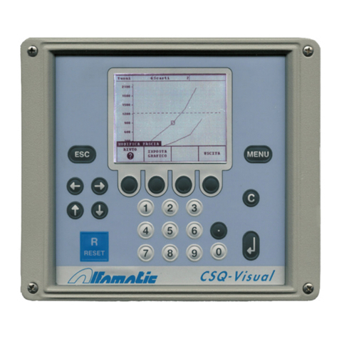
ALFAMATIC CSQ-Visual User manual

ALFAMATIC
ALFAMATIC PRESS -RIGHT User manual

ALFAMATIC
ALFAMATIC Press-Right User manual

ALFAMATIC
ALFAMATIC Press-Right User manual

ALFAMATIC
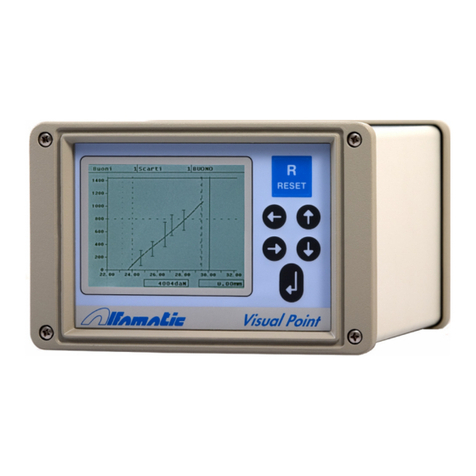
ALFAMATIC Visual Point User manual

ALFAMATIC
ALFAMATIC CSQ-Visual User manual

ALFAMATIC
ALFAMATIC CSQVIO8 User manual

ALFAMATIC
ALFAMATIC Press-Right User manual