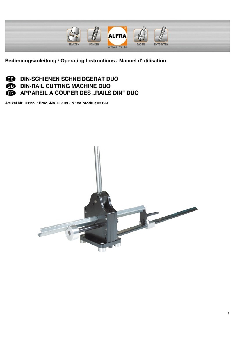
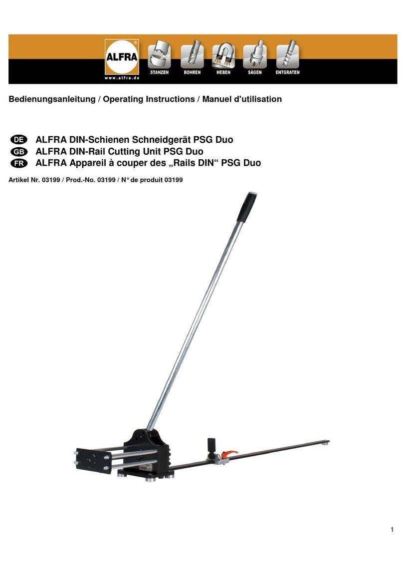
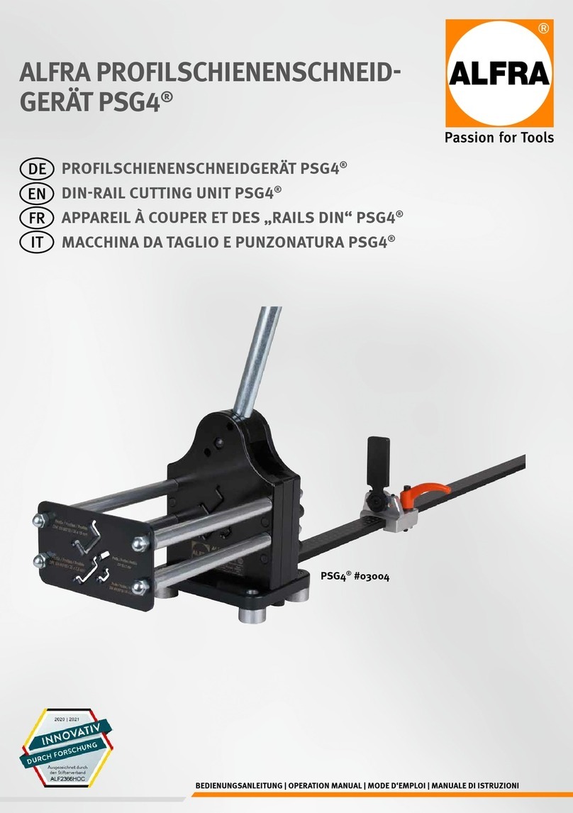
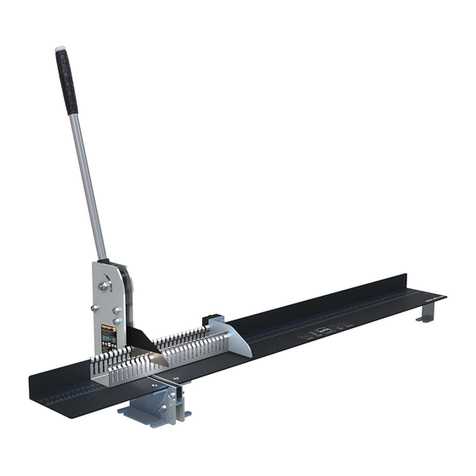
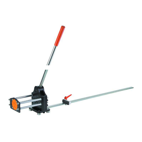
ALFRA 03250 User manual

Bedienungsanleitung - Operating Instructions - Mode d‘emploi
Stromschienenschneidgerät
Busbar Cutting Machine
Appareil à couper les barres conductrices
2010
Alfred Raith GmbH
2. Industriestraße 10
68766 Hockenheim
Tel. 06205-3051-0
FAX 06205-3051-150
Internet: www.alfra.de
E-Mail info@alfra.de

ALFRA
Stromschienenschneidgerät
Art. Nr. 03250
Zum sauberen Schneiden von Kupfer- und Alu-
minium-Stromschienen bis 120 x 12 mm
Ideales Ergänzungsgerät zum Stromschienen
Biege- und Lochstanzgerät.
Schneidezeit mit der Elektrohydraulikpumpe
SC 05 III, Art, Nr. 03851, je nach Schienenbreite
5 - 15 Sek.
Sauberes Schneiden durch Niederhalter und
Führungsvorrichtung zum zentrischen Schneiden.
Obermesser auswechselbar und nachschärfbar.
Das Gerät ist nicht geeignet zum Schneiden von
Baustählen oder Werkzeugstählen.
Gewicht: 16 kg
Art. Nr.
Grundgerät kpl. mit Schnellkupplung 03250
Ersatzobermesser 03251
Als Antrieb empfehlen wir wahlweise:
Elektrohydraulikpumpe SC 05 III 03851
Elektrohydraulikpumpe 02027
Bitte beachten Sie:
Die Stromschienen immer mittig und
rechtwinklig zum Schneidmesser
ausrichten!
Nur mit scharfem Schneidmesser
arbeiten!
Schneidmesser rechtzeitig
nachschärfen!
Greifen Sie niemals in den
Schneidbereich!

1. Wareneingang InVerbindungmitunserem4-Stationen-Kombi-
BearbeitungswagenistderSteckerdesFußschal-
Prüfen Sie bei Wareneingang alle Teile auf Voll- ters in die Diodenbuchse „SCHNEIDEN“ zu steck-
ständigkeit und äußere Beschädigungen. en. Die Betätigung erfolgt über den Fußschalter.
Informieren Sie bei Transportschäden sofort die
zuständige Spedition. Die Alfred Raith GmbH Am Stromschienenschneidgerät befindet sich kein
haftet nicht für Schäden, die während des Trans- Abschalter der den Schneidvorgang beendet.
portes aufgetreten sind. Im inneren des Hydraulikzylinders befindet sich
einAnschlag,aufdenderKolbenaufsetztund
damitdenDruckbiszumAbschaltendurchdas
2. Inbetriebnahme Überdruckventilansteigenlässt.
Bittebeachtensie:
Verbinden Sie das Schneidgerät mit der Zur Schonung des Stromschienenschneidgerätes
Hydraulikschlauchleitung der Hydraulikpumpe. und der Hydraulikpumpe empfehlen wir den
Vor dem Schneiden sollten Sie die Führungs- Schneidvorgang sofort nach dem Durchtrennen
vorrichtung derStromschienemitdemAusschalteramStrom-
so einstellen, daß die Stromschiene mittig und schienen- Biege und Lochstanzgerät zu beenden.
rechtwinklig geschnitten wird. Sollten Sie das Stromschienenschneidgerät mit
Dazu können die Spannschrauben gelöst und die einem Hand- oder Fußschalter bedienen gilt auch
seitlichen Führungsplatten entsprechend verscho- hier, sofortiges Abschalten nach dem Schneiden
ben werden. Ziehen Sie die Spannschrauben schont Gerät und Pumpe.
wieder an und stellen Sie den Niederhalter so tief
als möglich über das Material. 3. Sicherheitshinweise
So erreichen Sie winklige und gerade Schnitte.
DasSchneidgerätistfüreinenBetriebsdruckvon
Bei Benutzung eigener Hydraulikaggregate, 550 bar ausgelegt. Achten Sie darauf, daß alle im
beachten Sie bitte die entsprechenden System verwendeten Komponenten für diesen
Bedienungsanleitungen. max. Betriebsdruck ausgelegt sind.
In Verbindung mit unserem Stromschienen- Der Betrieb des Schneidgerätes sollte nur von
Biege- und Lochstanzgerät erfolgt die Betätigung geeigneten mit dem Gerät vertrauten Personen
über den „START“ Taster des Gerätes (beide durchgeführt werden.
Geräte sollten nebeneinander angeordnet sein).
BenutzenSiedasGerätnurzumSchneidenvon
Wird das Schneidgerät auf unserem Werkstatt- Kupfer- und Aluminium-Materialien in den ange-
wagen (als Option lieferbar Art.Nr. 03950) einge- gebenen Abmessungen
setzt in Verbindung mit dem Stromschienen-
Biege- und Lochstanzgerät, ist der Hebel des Sorgen Sie für einen sicheren Stand bzw. Befes-
Wegeventils in die Stellung „SCHNEIDEN“ zu tigung des Gerätes, wenn Sie es separat betrei-
legen. Die Schneidfunktion erfolgt dann über die ben.
„START“ Taste oder über den Fußschalter.
ArbeitenSievorzugsweisemitunserenHydaulik-
Wenn Sie das Schneidgerät separat mit unserer einheiten.
Hydraulikpumpe SC05 III betreiben wollen,
benötigen Sie den 3-pedaligen Fußschalter Bei eigenen Hydraulikaggregaten achten Sie auf
Art. Nr. 03863. (Start-Stop-Aus Funktion) den höchstzulässigen Hydraulikdruck von 550 bar.
Alfred Raith GmbH Telefon:06205/3051-0
Sägen- und Werkzeugfabrikation Telefax:06205/3051-150Inland
2. Industriestraße 10 3051-135Export
D-68766 Hockenheim Internet: www.alfra.de
E-Mail:info@alfra.de

For clean and flash-free cutting of copper and
aluminium busbars up to 120 x 12 mm
An ideal supplement to the busbar bending and
punching machine.
Cutting time with our electro-hydraulic pump
SC 05 III (Prod.-N°03851), 5 - 15 sec.
according to width of busbars
A clean cut because of a hold down and the guide
arrangement for centric cutting
Upper knife can be exchanged and re-sharpened
Weight: 16 kg
Prod.-n°
Basic unit complete with quick coupling
03250
Vice with centering jaws and
hold down, adjustable
03252
Spare upper knife 03251
As power source we recommend
one of the following:
Electro-hydraulic pump SC05 III.B 03852
Electro-hydraulic pump DSP120 02027
ATTENTION!
Busbar should always be inserted well
centered to the cutting knife!
Kindly assure that the upper knife is
sharp. Re-sharpen in time!
Keep your hands out of cutting zone!

1. Receipt of the Unit
After receipt of the unit please make sure that it is
complete and without any exterior damages.
In case of transport damage immediately inform
the responsible forwarder. Alfred Raith GmbH is
not liable for damages occurred during
transportation.
2. Preparation and Operation
Connect the cutting unit with the hydraulic hose of
the used pump.
Before starting operation the guidance should be
set in order to cut the busbar precisely centric.
Undo the tension screws and move the guidance
plates (at the sides) accordingly. Fasten the
tension screws and set the holddown as close to
the material as possible.
This way straight cuts in the correct angle are
achieved.
In case of use with own hydraulic unit please pay
attention to the valid operating manuals.
In connection with our busbar bending and
punching unit operation is as follows: Press the
„START“-button on the basic unit (if the units are
in side-by-side position.
If the cutting unit is used on our Workshop Cart
(available as accessory, prod. n°03950) in
connection with the busbar bending and punching
unit set the lever of the 3-way-valve to the
"CUTTING" position. Cutting operation can be
started by the "START"-button or the footswitch.
If you want to operate the cutting unit separately
with our hydraulic pump SC05III you need the 3-
pedal footswitch, prod.n°03 863 (Start-Stop-Off
function).
In connection with our 4-Station-Workshop-Cart
plug the footswitch cable into the diode socket
„CUTTING“, then do the set-up as previously
described. Operation by footswitch.
Attention:
There is no 'OFF' Switch on the Busbar Cutting
Machine that terminates the cutting process.Inside
the hydraulic cylinder there is a stopper that the
piston runs down on. When this happens, the
working pressure increases until the overload
valve comes into action, by which the machine is
stopped.In order to treat the Busbar Cutter and the
Electrohaydraulic Pump with care it is absolutely
necessary to stop the cutting process right after
the busbar is cut through, using the 'OFF' switch
on the Busbar-Bending and Punching Unit.In case
the Busbar Cutting Machine is operated with hand-
or footswitch:Also here immediate stopping
benefits machine and electrohydraulic pump.
3. Safety Hints and Remarks
The cutting unit is set for an operational pressure
of 500 bar. Take care that all components used in
this system are set for this maximum operational
pressure.
Unit may be operated by well-trained staff only.
Only use the unit to cut copper and aluminium
materials of the described dimensions.
Make sure, that the machine stands res. is
attached safely if operated separately.
Preferably work with our recommended hydraulic
units.
If hydraulic units are used different from ours,
obey max. pressure of 550 bar.

Warranty
The manufacturer provides a 12-month warranty. This warranty applies
only if this operation manual is followed and if the unit is used correctly.
The manufacturer accepts no liability for damage resulting from incorrect
use of the unit or the ignoring of the stipulations and rules of behaviour
specified in this operation manual.
There shall be no possibility of making warranty claims against the
manufacturer if unauthorised changes are made to the construction or
functional configuration of the S125 busbar cutting unit without the
manufacturer's written approval.
The General Terms of Business and Delivery of Alfred Raith GmbH,
68766 Hockenheim, Germany apply in all cases.
Alfred Raith GmbH Phone +49 6205 3051 0
P.O. Box 1667 Fax +49 6205 3051 150
D-68759 Hockenheim E-Mail: export@alfra

Appareil à couper les
barres conductrices ALFRA
N. art. 03250
Pour couper proprement et sans bavure les
barres conductrices de 120 x 12 maximum.
Appareil complémentaire idéal à l’appareil de pliage
et de perçage des barres conductrices.
Le temps de coupe avec la pompe électro-
hydraulique varie, de 5 à 10 secondes, selon la
largeur de la barre conductrice.
Coupe propre et exacte grâce au serre-flan ajustable
et au dispositif de centrage de coupe.
La lame supérieure peut être changée et réaffûtée.
Cet appareil ne doit pas être utilisé pour la coupe
d’aciers de construction ou d’aciers à outils.
Poids: 16 kg
N°.art.
Appareil de base avec raccord rapide
03250
Dispositif de centrage avec serre-
flanc,ajustable
03252
Lame supérieure de rechange 03251
Comme pompe, nous recommandons
au choix :
Pompe électro-hydraulique SC 05 III 03851
Pompe électro-hydraulique 02027
ATTENTION!
Attention, avant de couper , veuillez
toujours centrer les rails par rapport à
la lame supérieure
La lame supérieure doit toujours être
bien aiguisée. Un réaffûttage
régulièrement s’impose.
Ne laissez pas vos doigts près de la
lame

1. Réception de la marchandise
A la réception de l’appareil, veuillez vérifier s’il est
complet et s’il n’a pas subi des dégâts extérieurs.
En cas de dommages dûs au transport, veuillez
informer immédiatement le transporteur
responsable. Alfred Raith GmbH n’est pas tenu
responsables des dommages occasionnés
pendant le transport.
2. Mis en service
Veuillez raccordez l’appareil à couper les barres
au tuyau hydraulique se trouvant sur la pompe
hydraulique utilisée.
Avant de couper, vous devez régler le serre-flanc
(pouvant optionnellement être commandé de
façon à ce que la barre conductrice puisse être
coupée au centre et à angle droit.
Détachez les écrous tendeurs et déplacez les
plaques de guidage situées sur le côté. Refixez
les écrous tendeurs et ajustez le serre-flanc le
plus bas possible au dessus du matériau à
couper. Ceci vous permettra de couper à angle
droit et sans bavure.
Si vous utilisez votre propre pompe hydraulique,
veuillez respecter la notice explicative
correspondante.
Si vous utilisez cet appareil à couper les barres
avec notre appareil de pliage et de perçage des
barres conductrices (N°.art.03 200), veuillez
appuyer sur la touche “START” de l’appareil de
base (N°0 3200), (les 2 appareils devraient se
trouver l’un à côté de l’autre).
Si l’appareil à couper les barres doit être placé
sur le chariot d’atelier ALFRA (pouvant
optionnellement être commandé cf. n°art. 03 950)
et doit être utilisé avec l’appareil de pliage et de
perçage des barres conductrices, veuillez mettre
le levier de la soupape à 3 voies à la position
“Schneiden/Cutting”. Il vous sera alors possible de
couper en appuyant sur la touche “START” ou
bien en activant la pédale de commande.
Si vous souhaitez faire fonctionner l’appareil à
couper les barres séparement avec notre pompe
SC 05 III, vous avez besoin de la pédale de
commande N°. art. 03863 (aux 3 fonctions Start-
Stop-Aus)
Alfred Raith GmbH
P.O. Box 1667
D-68759 Hockenheim
Si l’appareil à couper les barres est utilisé avec le
chariot d’usinage combiné à 4 postes de travail,
il faut alors brancher la prise de la pédale de
commande à la douille de diodes portant la
mention CUTTING/SCHNEIDEN”. Il est alors
possible de couper en activant la pédale de
commande.
Attention:
L’appareil à couper les barres n’est pas équipé
d’interrupteur pouvant stopper la fonction de
coupe. A l’intérieur du cylindre hydraulique, se
trouve une butée, sur laquelle repose le piston,
laissant ainsi monter la pression jusque ce que la
mise hors service soit atteinte par l’intermédiaire
de la soupape de sur-pression.
Pour ménager l’appareil à couper les barres et la
pompe hydraulique, nous recommandons, dès
que la barre a été partagée, de terminer
l’opération de coupe en appuyant sur
l’interrupteur de l’appareil de pliage et de
poinçonnage. Si l’appareil à couper les barres est
mis en service par une commande à main ou à
pédale, il est recommandé pour son ménagement
ainsi que pour celui de la pompe d’arrêter
l’appareil dès que celui-ci a terminé l’opération de
coupe.
3. Consignes de sécurité
L’appareil à couper les barres est réglé pour
pouvoir travailler avec une pression de 550 bars.
Veillez à ce que toutes les composantes de
l’appareil soient également réglées à cette
pression maximum.
Si vous utilisez, d’autres unités hydrauliques que
celles que nous préconisons, nous vous
demandons de respecter cette pression
maximale. Essayez dans la mesure du possible
de travailler avec les pompes hydrauliques
ALFRA.
Cet appareil a été conçu uniquement pour couper
des barres en cuivre ou en aluminium aux
dimensions indiquées, à savoir de 120 x 12 mm.
Veillez à installer de façon stable l’appareil à
couper les barres, si l’appareil est utilisé seul, il est
nécessaire de le fixer solidement.
Cet appareil ne doit être mis en service que par un
opérateur conscient des règles de sécurité
élémentaires.
Phone: +49-6205-2098 8
Fax: +49-6205-2098 135
Internet: www.alfra.de
E-mail: export@www.alfra.de


Ersatzteilliste Stromschienen-
Schneidgerät Art. Nr. 03250
Spare parts list Busbar cutting
equipment part no. 03250
Liste de pièces détachées couper les barres
conductrices ref. art. 03250
Pos.
Benennung Description Description St/P
c Art. Nr.
1 Gegenmesser (gehärtet) counter knife contre-outil 203250-001
2 Abstands-Platte distance plate plaque écarteuse 2 03250-002
3 Messer (gehärtet) knife outil (article no. 03251) 103250-003
4 Zylinderschraube ISO 4762 - M6 x 22 - 8.8 cylinder-head screw vis à tête cylindrique 2 DIN912-M6X22-8.8
5 Messerbalken knife holder fixation de l'outil 1 03250-005
6 Stift centering pivot w. elast. thrust piece pivot de logement 1 03250-006
6A Federndes Druckstück spring-loaded thrust pad patin de serrage élastique
1 03250-006A
7 Zylinderschraube ISO 4762 - M8 x 65 - 8.8 cylinder-head screw vis à tête cylindrique 4 DIN912-M8X65-8.8
8 Zylinderstift ISO 8734 - 10m6 x 70 cylinder-head pin goupille cylindrique 4 DIN6325-10m6X70
9 Druckfeder d=7 Dm=50 LO=128 n=6,5 compression spring ressor à pression 1 03250-009
10 Platte (Plexiglas) Plexiglass protection protection en plexiglass 1 03250-010
11 Platte (Plexiglas) Plexiglass protection protection en plexiglass 1 03250-011
12
13 Kolben (gehärtet) piston, complete piston complet 1 03250-013
14 Zylinderdichtung 45x65x10 cylinder packing-box garniture de cylindre 1 03250-079
15 Zylinder cylinder cylindre 1 03250-015
16 Winkeleinschraubadapter elbow-type scewing vissement coudé 1 03250-077A
17 Hydraulik-Nippel 1/4" NPT IG hydraulic nipple raccord hydraulique 1 03250-077
18
19 Stopfen Miramid Ø20 plug Ø20 bouchon 1 03250-019
20 Flachkopfschraube ISO 7045 - M4 x 8 - 4.8 pan-head screw vis à tête plate 8 DIN7985-M4X8-4.8
21 Anschlagring (gehärtet) sleeve/bush douille 1 03250-021
22 Sechskantmutter ISO 8673 - M16 x 1,5 - 8: hexagon nut écrou hexagonal en acier 1 DIN934-M16X1,5-8
23 Klemmhebel clamping lever levier de serrage 2 03250-023
24 Sechskanntschraube bearbeitet DIN961 hexagon scew vis 1 03250-024
25 Winkel angle angle 1 03250-025
26 Winkel angle angle 1 03250-026
27

28 Zylinderschraube ISO 4762 - M6 x 10 - 8.8 cylinder-head screw vis à tête cylindrique 3 DIN912-M6X10-8.8
29
30 Zylinderschraube ISO 4762 - M8 x 16 - 8.8 cylinder-head screw vis à tête cylindrique 4 DIN912-M8X16-8.8
31 Platte plate plaque 1 03250-031
32 Flachrundschraube ISO 8677 - M6 x 20 - 4.6
round-head screw vis à tête rectangulaire 2 DIN603-M6X20-4.6
33 Stahlmaß 0 - 109 mm steel measuring tape e'talon en acier 2 03250-033
34 Platte plate plaque 1 03250-034
35 Platte plate plaque 1 03250-035
36 Typenschild 03250 type label plaque caractéristique 1 03250-036
37 Hinweisschild 03250 label étiquette 1 03250-037
38 Aufkleber "Made In Germany" (mittel) adhesive label autocollant 1 609.305/107
39 Passscheibe DIN 988 - 6 x 12 x 0,5 adjusting washer poulie 3 DIN988-6X12X0,5
40 Baugruppe Schneidgerät cutting machine unit module de construction 1 03250-040
Table of contents
Languages:
Other ALFRA Cutter manuals
Popular Cutter manuals by other brands

BE Ag & Industrial
BE Ag & Industrial BE-RC Series Operations & parts manual

Huskie Tools
Huskie Tools REC-434YC Operating instructions manual

Lux Tools
Lux Tools FSM-200 Original instructions

Woods
Woods BW240X Operator's manual

wurth
wurth MSF 30 operating instructions

Helvi
Helvi PC EVO 66 instruction manual