BRIDGE DECK FINISHER SET-UP GUIDE - 069596Page 8
BDF Assembly & Set-up
STRAIGHTENING CARRIAGE RAIL
• For string-lining the carriage rail, use nylon masonry line.
DANGER: USE ONLY STRING-LINE PROVIDED WITH BDF
• Attached the string-line from eye bolt to eye bolt on each
end of the BDF. These are located at the base of each end
panel. DO this step for both sides of the frame.
• Tighten the string-line by pulling it taut with no sag. It may
be necessary turn the eye-bolts to gain additional tension on
the string (NO SAG)
• The carriage rail adjuster lock nuts need to be loosened
to allow movement of the carriage rail.
CAREFUL not to make them too loose.
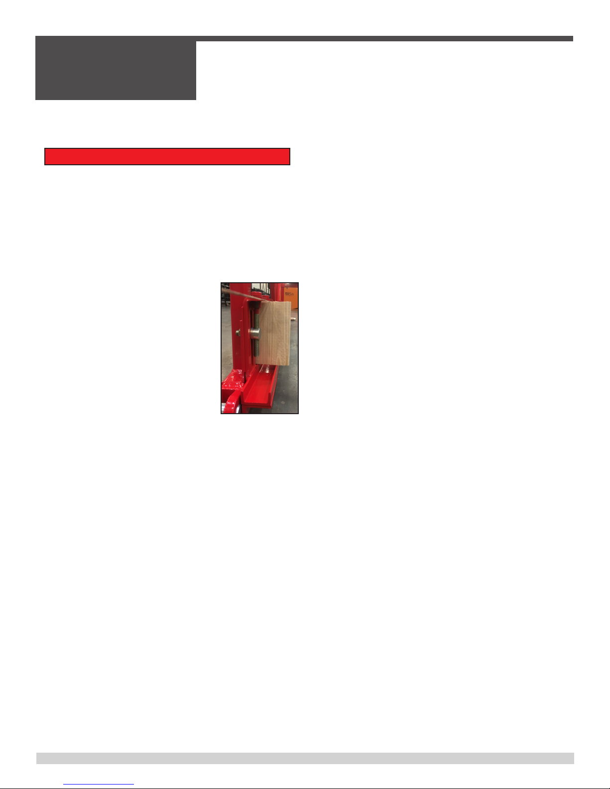
• You will need (4) - 2” x 6” wood blocks,
use the factory edge for the string-line to
rest on & the other factory edge resting
on the carriage rail (SEE PICTURE).
• Any number of items can be used to
check the carriage rail height to the
string-line – Wood block, chamfer strip,
grade stake.
• Adjust the carriage rail holder bolt up or down so that the
carriage rail matches the same height across the frame.
• When the carriage rail adjustment has been completed and
looks straight, tighten all of the carriage rail locknuts. SAME
ON BOTH SIDES.
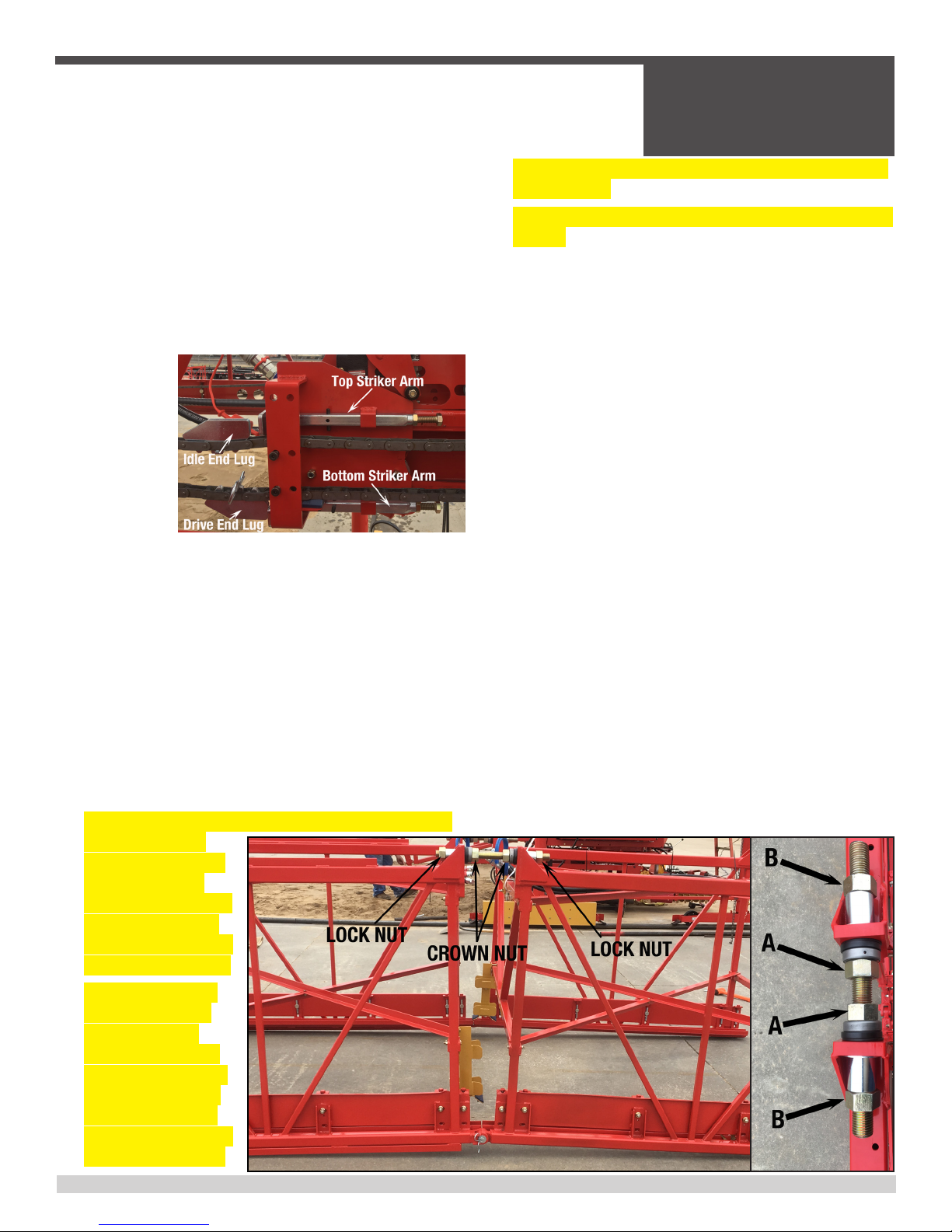
SQUARING THE PAVING CARRIAGE
• Make sure that the lower carriage slide blocks make contact
with the upper carriage skew ring and there are no gaps.
MAY NEED SHIMS.
• Make sure that the lower carriage is in the down position
and look at the blocks against the ring.
• If there are gaps, remove the cotter pin and turn the castle
nut located under side of the upper - lower carriage. Also
check for wear on the slide blocks, may need replacing.
• After starting the engine, engage the on/off lever to shift the
lower carriage by manually pushing or pulling the reversing
valve rod.
• Adjust the turntable pivot nut until lower carriage pivots
freely and there are no gaps, shut off the engine and replace
the cotter pin in the castle nut.
• Align the paving rollers so that they are parallel with the
upper carriage.
• Use a level, metal bar or string-line across the top of each
side of the upper carriage from carriage rail to carriage rail.
• Place a 4’-6’ long straight edge or level across the top or
the bottom of both ends of the paving rollers.
• Measure the distance from the top of the carriage rail to the
bottom of the paving roller, which is top of concrete grade
and make sure this is the same on all 4 roller corners.
ADJUSTING THE PAVING ROLLERS
• To adjust the elevation of the paving rollers, ONLY loosen the
bolts on the front of the carriage holding the roller bearing.
• Also, ONLY loosen the bolts that support the motor mount
plates on the back of the lower carriage.
• Using a tape measure or wooden ruler, measure down from
the string-line to the top of the straight edge or level.
• The distance must be the same at all four corners.
• Adjust the elevation of each roller end by turning its adjuster
bolt clockwise to raise and counter clockwise to lower.
• When all four corners are equal, the paving rollers will be
parallel with the carriage rail.
• Tighten all loose mounting bolts.
• Use the auger adjusting crank and reset the augers to 1/8”
to 1/4” above the bottom of the paving rollers.
ROLLERTAMPERS
• The roller tamper drums are used to consolidate the top
surface of the concrete with the desired density.
• It helps to seal hard to nish concrete with harsh mix
designs and low slumps.
• It may also help to seal when dealing with wind exposure,
causing abnormal surface drying and unforeseen delays in
the concrete delivery.
• Place a 4’-6’ level under the paving rollers and under the
roller tamper drum to check the elevation.
• Loosen the locking set screws and the lock nuts for the
drum adjustment on both sides of the roller tamper with the
front and back set to grade.
• The drums can be adjustable from 1/2 inch above concrete
grade to 3/4 inch below concrete grade.