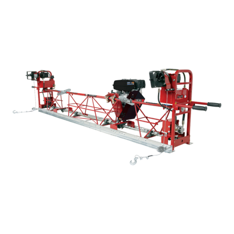
allen SSE12 Application guide

OPERATIONS & PARTS MANUAL
SSE12 SCREED
Manual Part #: 064633 I REVISION: B

This manual, or a copy of it, must be kept with the machine at all times.
There is a manual storage container located on the machine for your
convenience.

Engine Driven Screed
OPERATIONS - PARTS MANUAL
This manual covers the products listed below:
Part No. Description
028379 Screed, Truss, Steel, Engine Driven, SSE12,10.0’ Section (3.1m)
022378 Screed, Truss, Steel, Engine Driven, SSE12, 7.5’ Section (2.3m)
022379 Screed, Truss, Steel, Engine Driven, SSE12, 5’ Section (1.5m)
027986 Screed, Truss, Steel, Engine Driven, SSE12, 2.5’ Section (.76m)
022380 Screed, Truss, Steel, Engine Driven, SSE12, 2’ Section (.61M)

050362Page 4
Section Title Page
--- Limited Warranty .........................................................................................................4
--- Table of Contents ........................................................................................................5
--- Information Contained In This Manual..........................................................................7
--- Dealer Information.......................................................................................................8
--- Ordering Parts .............................................................................................................9
--- Model Number - Serial Number Codes ......................................................................10
--- UnitIdentication ......................................................................................................11
--- Technicalspecications.............................................................................................12
--- EngineSpecications ................................................................................................13
--- LiftingSpecications .................................................................................................14
--- Transportation ...........................................................................................................15
--- Standard Machine Dimensions ..................................................................................16
Section 1 - Safety
1.1 State Regulations ......................................................................................................18
1.2 Federal Regulations...................................................................................................19
1.3 Safety Information.....................................................................................................20
1.4 Safety Symbols .........................................................................................................21
1.5 General Safety...........................................................................................................22
1.6 Sound & Vibration Analysis ........................................................................................29
Section 2 - Operations
2.1 Pre-Operating Instructions.........................................................................................32
2.2 Operating Instructions ...............................................................................................33
2.3 Lifting Procedures .....................................................................................................34
2.4 Section Assembly ......................................................................................................35
2.5 Attaching Winches.....................................................................................................36
2.6 Determining Left and Right........................................................................................37
2.7 End Handle Assembly................................................................................................38
2.8 Engine Mount assembly ............................................................................................39
2.9 String Lining..............................................................................................................40
Section 3 - Service
3.1 Periodic Maintenance Schedule.................................................................................42
Table of Contents

050362 Page 5
Section 4 - Parts
--- Factory Service Information.......................................................................................44
--- Replacement Parts Procedures..................................................................................45
4.1 Engine Mount............................................................................................................46
4.2 2’ Section..................................................................................................................48
4.3 2- 1/2’ Section ..........................................................................................................50
4.4 5’ Section..................................................................................................................52
4.5 7- 1/2’ Section ..........................................................................................................54
4.6 10’ Section................................................................................................................56
4.7 End Handle................................................................................................................58
4.8 Winch Assembly........................................................................................................60
4.9 Hydraulic Winch Assembly.........................................................................................62
4.10 Flex Coupler ..............................................................................................................66
4.11 U-Joint......................................................................................................................67
4.12 Crown Invert Bracket.................................................................................................68
4.13 End Mount Engine Assembly......................................................................................70
4.14 Decals, Standard SSE12............................................................................................72
4.15 Decals, Hydraulic.......................................................................................................73
--- Revision Details.........................................................................................................74
--- Copyright Information................................................................................................75
Table of Contents, continued

050362Page 6
Allen Engineering Corporation (“Allen”) warrants its products to be free of defects in material or workmanship for:
TWO YEARS FROM END USER’S DATE OF PURCHASE
Warranty period begins on the date of purchase by the End User of the product. All warranty is based on the following limited warranty
terms and conditions, including the disclaimer of implied warranties and consequential damages.
1. Allen’s obligation and liability under this warranty is limited to repairing or replacing parts if, after Allen’s inspection, there is de-
termined to be a defect in material or workmanship. Allen reserves the choice to repair or replace.
2. If Allen chooses to replace the part, it will be at no cost to the customer and will be made available to the Allen Distributor, Dealer,
or Rental Center from whom the End User purchased the product.
3. Replacement or repair parts, installed in the product, are warranted only for the remainder of warranty period of the product as
though they were the original parts.
4. Allen does not warranty engines or batteries. Engine warranty claims should be made directly to an authorized factory service
center for the particular engine manufacturer. Batteries are not warranted due to unknown treatment during transport, etc, and
any battery claims should be directed to the battery manufacturer.
5. Allen’swarrantydoesnotcoverthenormalmaintenanceofproductsoritscomponents(suchasenginetuneupsandoil<er
changes). The warranty also does not cover normal wear and tear items (such as belts and consumables).
6. Allen’s warranty will be void if it is determined that the defect resulted from operator abuse, failure to perform normal maintenance
ontheproduct,modicationtoproduct,alterationsorrepairsmadetotheproductwithoutthewrittenapprovalofAllen.Allen
specicallyexcludesfromwarrantyanydamagetoanytrowelsresultingfromanimpacttotherotors.
7. Impact damage to gear boxes is not covered under the Allen warranty and is deemed customer abuse.
8. Allen will pay shop labor on warranty items at the Allen Shop Labor Rate in existence on the date of the warranty claim. An Allen
labor chart will determine the time allowed to complete a repair and will govern the shop labor hours that will be allowed.
9. Allen will pay freight on warranty replacement parts at worldwide standard ground rates. No warranty replacement parts will be
shipped air freight at the expense of Allen. Allen only pays outbound freight charges when sending warranty replacement parts to
the customer via ground service. Allen does not pay any inbound freight. However, if Allen determines this to be a warranted item,
only then will Allen reimburse the customer for inbound freight at standard ground rates.
10. ALLEN ENGINEERING CORPORATION’S WARRANTY POLICY WILL NOT COVER THE FOLLOWING: TAXES;
11. SHOP SUPPLIES; ENVIRONMENTAL SURCHARGES; AIR FREIGHT; TRAVEL TIME; LOSS OF TIME; INCONVENIENCE; LOSS OF RENTAL
REVENUE; RENTAL COSTS OF EQUIPMENT USED TO REPLACE THE PRODUCT BEING REPAIRED;
12. LOSS OF USE OF THE PRODUCT; COMMERCIAL LOSS; OR ANY OTHER CHARGES WHATSOEVER OR ANY LIABILITIES FOR DIRECT,
INCIDENTAL, OR CONSEQUENTIAL DAMAGE OR DELAY.
13. ALLEN ENGINEERING CORPORATION MAKES NO OTHER WARRANTY, EXPRESSED OR IMPLIED. THIS LIMITED WARRANTY IS IN
LIEU OF THE WARRANTY OF MERCHANTABILITY AND FITNESS. THERE ARE NO OTHER WARRANTIES THAT EXTEND BEYOND THE
DESCRIPTION ON THIS DOCUMENT.
14. No Allen employee or representative is authorized to change this warranty in any way or grant any other warranty
15. unlesssuchchangeismadeinwritingandsignedbyanofcerofAllenEngineeringCorporation.
Limited Warranty

050362 Page 7
This manual provides information and procedures to safely operate and maintain the Allen Machine.
For your own safety and protection from personal injury, carefully read, understand, and observe the
safety instructions described in this manual. Keep this manual or a copy of it with the machine at all
times.
ALWAYS operate this machine in accordance with the instructions described in this manual. A well main-
tained piece of equipment will provide many years of trouble free operation.
This manual is divided into the following sections:
Complete any warranty requirements as specified by the engine manufacturer in their instructions found
inside the manual box located on the back of the riding trowel operator’s seat.
Your engine and clutch is not manufactured by Allen Engineering Corporation, Inc, and therefore is not
covered under Allen Engineering Corporation, Inc warranty.
Your engine manufacturer should be contacted if you wish to purchase a parts manual or a repair man-
ual for your engine.
Refer to enclosed owners engine manual for complete O&M instructions. See your battery manufacturer
for battery warranty.
SECTION 1
SAFETY
SECTION 2
OPERATIONS
SECTION 3
SERVICE
SECTION 4
PARTS
Information Contained
In This Manual

050362Page 8
Dealer Name: _____________________________________________________________
Phone #: (____) - ____ - ____________________________________________________
Address: ________________________________________________________________
City:__________________________________State:________ Zip:___________________
Salesman: _______________________________Mobile Phone _____________________
Additional Comments: ______________________________________________________
________________________________________________________________________
________________________________________________________________________
Your Dealer has Allen Engineering Corporation trained mechanics and original Allen replacement parts. Always contact the
AllenDealerwhosoldyouthismachineforAllenCertiedrepairsandreplacementparts.
Place Allen Dealer information below for future reference.
Dealer Information

050362 Page 9
Ordering Parts
Section 4.0 contains illustrated parts lists for help in ordering replacement parts for your machine. Follow the instructions
below when ordering parts to insure prompt and accurate delivery:
1. All orders for service parts - include the serial number for the machine. Shipment will be delayed if this information
is not available.
2. Include correct description and part number from the “PARTS” section of this manual.
3. Specify exact shipping instructions, including the preferred routing and complete destination address.
4. DO NOT return parts to AEC without receiving written authorization from AEC. All authorized returns must be shipped
pre-paid.
5. When placing an order, please contact the AEC dealer nearest you.
ALL INFORMATION, SPECIFICATIONS, AND ILLUSTRATIONS IN THIS MANUAL ARE
SUBJECT TO CHANGE WITHOUT NOTICE AND ARE BASED ON THE LATEST
INFORMATION AT THE TIME OF PUBLICATION.

050362Page 10
Manufacturer’s Codes:
When ordering parts or requesting service information, you will ALWAYS be asked to specify the model and serial numbers
ofthemachine.Thelegendsbelow specicallydeneseachsignicant character or group ofcharactersof the Model
Number and Serial Number codes.
Model Number
T150 B
Series
B
Triple Roller Tube Paver
150
Serial Number
Theserialnumberfoundontheidenticationplateisatendigitformat.Themodelnumberidentiesyourmachineandwill
ensure that you receive the correct replacement parts.
Serial Number Example
T15 14 01 180
Series
Sequence Number
Year
Month
Model Number - Serial Number Codes

050362 Page 11
Unit Identication Plate Location:
Anidenticationplatelistingthemodelnumberandtheserialnumber is attached to each unit and is located on the top left
corner of the operator end handle. See image below for serial number plate location. This plate should not be removed at
any time.
Pleaserecordtheinformationfoundonthisplatebelowsoitwillbeavailableshouldtheidenticationplatebecomelostor
damaged. When ordering parts or requesting service information, you will ALWAYS be asked to specify the model and serial
numbers of the machine.
FILL IN FOR FUTURE REFERENCE
Model Number:____________________________
Serial Number:____________________________
Date Purchased:___________________________
Purchased From:___________________________
Unit Identification

050362Page 12
Engine Powered Screed Specications
Recommended Slump 3 in (76 mm)
Max. Concrete Depth 8 in (203 mm)
Max Screed Width 65 ft (19.8 m)
PART # DESCRIPTION Weight lb. (kg)
022380 2’ (.61 m) truss with eccentric shaft vibration 37 (17)
027986 2.5’ (.76 m) truss with eccentric shaft vibration 46 (21)
022379 5’ (1.5 m) truss with eccentric shaft vibration 90 (41)
022378 7.5’ (2.3 m) truss with eccentric shaft vibration 135 (61)
028379 10’ (3.1 m) truss with eccentric shaft vibration 180 (82)
ACCESSORIES
PART # DESCRIPTION Weight lb. (kg)
025894 End handles (two each) 36 (16)
018993 Manual Winches, set of two 40 (18)
028363 Hydraulic Winches, includes 2.5’ truss 261 (118)
527001 Adjustable end brackets with rollers 22 (10)
527000 Adjustable end brackets without rollers 20 (9)
046708 Invert/crown kit, for adjustments up to ¼-inch per foot 12 (6)
027879 9HPEngineLowProleKit 115 (52)
028327 11HPEngineLowProleKit 118 (54)
543000 Truss screed dolly (standard) 45 (20)
543001 Truss screed dolly (heavy duty) 87 (39)
• Top Pipe - Coupling System - Fine Thread Adjustment 1 5/16-16tpi with Full Flow 1” Non-Restricting Air System
with Dual Locking Jam Nuts.
• Vibration Proff Welds with Exclusive Vibration-Dampening System.
• Bolt-On Blades with Quick Connecting Splice Plates Front and Back at Each Truss Section using 1/2-13 Nuts and
Bolts Throughout.
• Balanced Design Truss Height to OVerall Base Width Provides Equilateral Triangle Strength for Obtaining Precise
Grade Control. and Structure Integrity.
• Top Pipe Coupling System Provides for Crowned or Invert Slab Section without Loosening Bottom Splice Blade
Bolts. Special Crowns or Inverts are obtainable with Ball Joint Top Pipe Coupler or Crown Invert Bracket. Crowns
greater then 1/8”/ft are considered special.
• NOTE: Select Screed Width to Allow Minimum Overhangs Past Forms; 6” Overhangs are Ideal.
Technical Specifications

050362 Page 13
MODEL Honda GX270 Honda GX340
Type Air-cooled 4 stroke, Single Cylinder, OHV, Horizontal
Shaft Gasoline Engine
Air-cooled 4 stroke, Single Cylinder, OHV, Horizontal
Shaft Gasoline Engine
Bore X Stroke 3.0 in. X 2.3 in. (77 mm x 58 mm) 3.4 in. X 2.5 in. (88 mm x 64 mm)
Displacement 16.4 cu-in. (270 cc) 23.7 cu-in. (389 cc)
Max. Output 9.0 H.P. @3600 RPM 11.0 H.P. @3600 RPM
Fuel Tank Capacity Approx. 1.95 U.S. Gallons (6.0 Liters) Approx. 1.95 U.S. Gallons (6.0 Liters)
Fuel Unleaded Gasoline Unleaded Gasoline
Lube Oil Capacity 1.06 qt. (1.1 liters) 1.06 qt. (1.1 liters)
Oil Type 4-Stroke API, SFor SG SAE 10W-30 General Use 4-Stroke API, SFor SG SAE 10W-30 General Use
Speed Control Method Centrifugal Fly-weight Type Centrifugal Fly-weight Type
Cooling System Forced Air Forced Air
Starting Method Recoil Start Recoil Start
Spark Plug Type BPR6ES NGK BPR6ES NGK
Spark Plug Gap 0.028-0.031 in. (0.70 - 0.80 mm) 0.028-0.031 in. (0.70 - 0.80 mm)
Dimension (L x Wx H) 15.0 x 16.8 X 16.6 in. (381 X 428 X 422 mm) 15.9 x 18.1 X 17.6 in. (406 X 460 X 448 mm)
Dry Net Weight 55.1 lbs (25 Kg.) 69.8 lbs (31.7 Kg.)
Engine Specifications

050362Page 14
The following procedure and illustration describe how to lift the screed.
• Attach the U-shaped lifting bracket and associated hardware to the top of each truss frame section as shown in the
illustration below. Tighten bracket securely so that it will not slip.
• Utilize a spreader bar of proper length and lifting capacity. Secure lifting straps from both ends of the
spreader bar to the attached lifting brackets.
• Connect lifting cables from the spreader bar to the lifting hook of a crane or forklift. Ensure that the lifting hook and
chain are of appropriate lifting capacity.
• Usecraneorforklifttohoistscreedontoaatbedtruckfortransportingorontotheformforscreeding.
Lifting Specifications

050362 Page 15
Placethescreedonaatbedtruckoratrailerduringtransportationasshownbelow.Attachsuitabletie-downstrapstothe
screed to secure it. Route tie-down straps over truss frame sections as required.
STRAP
STRAP
Transportation

050362Page 16
17.4
16.7
4.0 3.0
2.5
24
30 60
120
The dimensions of the air
powered screed in this manual
are illustrated on this page. the
geight and width are in Figure 1
and the lengths of the different
screed sections available are
illustrated in Figure 2.
FIGURE 1
FIGURE 2
90
2' SECTION
2-1/2' SECTION
5' SECTION
7-1/2' SECTION
10' SECTION
21.187
57.187
87.187
116.650
Standard Machine Dimensions

SECTION 1
SAFETY
050362 Page 17
SECTION 1
SAFETY

SECTION 1
SAFETY
050362Page 18
State Regulations
Proposition 65 Warning

SECTION 1
SAFETY
050362 Page 19
Federal Regulation
Respiratory Hazard

SECTION 1
SAFETY
050362Page 20
DO NOT operate or service the equipment before reading the entire manual. Safety precautions should be followed at all
times when operating this equipment. Failure to read and understand the safety messages and operating instructions could
result in injury to yourself and others.
SAFETY NOTES
The four safety notes shown below will inform you about potential hazards that could injure you or others. The safety notes
specicallyaddressthelevelofexposuretotheoperatorandareprecededbyoneoffourwords:DANGER,WARNING,CAU-
TION or NOTICE.
Indicates a hazardous situation which, if not avoided,
will result in death or serious injury.
Indicates a hazardous situation which, if not avoided,
could result in death or serious injury.
Indicates a hazardous situation which, if not avoided,
could result in minor or moderate injury.
Addresses practices not related to personal injury.
Safety Information
Table of contents
Other allen Construction Equipment manuals
Popular Construction Equipment manuals by other brands

Kubota
Kubota KC120HC Operator's manual

Manitowoc
Manitowoc 2250 Operator's manual

Dhatec
Dhatec V-Sup Application Procedure Specification

Chicago Pneumatic
Chicago Pneumatic CP 0112 Safety and operating instructions

RICE HYDRO
RICE HYDRO DIRTDAWG-TM11 Assembly instructions

Fayat
Fayat Dynapac CC1100C VI instruction manual

MSI
MSI MSI-9300HT Setup exit guide supplement

Auto Crane
Auto Crane 3203 PR: 3203 PRX owner's manual

Doka
Doka Framax stripping corner I Series Original operating instructions

JAVAC
JAVAC JAV-1021 Safety instructions & operation manual

Manitowoc
Manitowoc National Crane 900H Operator's manual

Bomag
Bomag BT 60/4 operating instructions