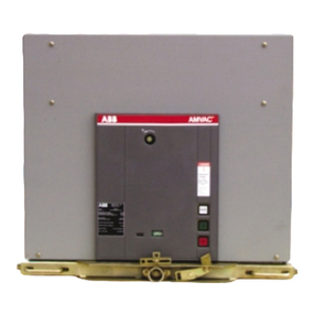
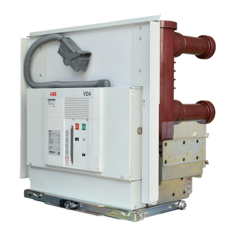
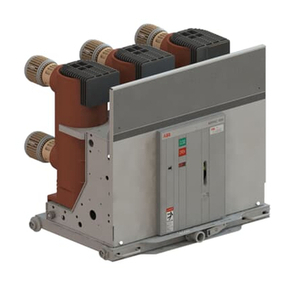
ABB ADVAC 03 Installation and operating instructions

1 ABB IB 6.2.15.7-1C
ADVACTM Model 03 Medium Voltage
Vacuum Power Circuit Breakers and Auxiliary
Installation/Maintenance Instructions
IB 6.2.15.7-1C
November 2005

2
ABB IB 6.2.15.7-1C
TABLE OF CONTENTS
FORWARD................................................................................................................................................................3
INTRODUCTION & SAFE PRACTICES ...................................................................................................................4
Introduction...................................................................................................................................................4
Safe Practices ..............................................................................................................................................4
RECEIVING, HANDLING, & STORAGE ..................................................................................................................5
Receiving......................................................................................................................................................5
Handling .......................................................................................................................................................5
Storage .........................................................................................................................................................5
INSERTION AND REMOVAL ...................................................................................................................................6
Insertion........................................................................................................................................................ 6
Removal .......................................................................................................................................................6
Racking......................................................................................................................................................... 7
MECHANISM AND OPERATION .............................................................................................................................9
Description of Mechanism Operation ...........................................................................................................9
Interlocks ....................................................................................................................................................11
Manual Operation .......................................................................................................................................12
Electrical Operation ....................................................................................................................................13
Control Scheme.......................................................................................................................................... 14
MAINTENANCE ......................................................................................................................................................16
Mechanism ................................................................................................................................................. 16
Truck........................................................................................................................................................... 18
Control Wiring............................................................................................................................................. 19
Primary Circuit ............................................................................................................................................19
G&T DEVICE........................................................................................................................................................... 21
DUMMY BREAKER DEVICE.................................................................................................................................. 23
OPTIONAL ACCESSORIES...................................................................................................................................24
Lifting Hook.................................................................................................................................................24
APPENDICES ......................................................................................................................................................... 25
Appendix A: Basic Breaker Layout ............................................................................................................. 25
Appendix B: Basic Breaker Dimensions and Weights...............................................................................26
Appendix C: Close/Open Coil Data ...........................................................................................................29
Appendix D: Wiring Diagrams ................................................................................................................... 30
Appendix E: Circuit Breaker Renewal Parts ..............................................................................................32

3 ABB IB 6.2.15.7-1C
This booklet provides information for the ADVAC breakers as described below. Not all sections of the bulletin apply
to all types of ADVAC circuit breakers. For example, the racking and interlock sections do not apply to the fixed
mount breaker styles. All information in this booklet was current at the time of printing.
Style Frame Width
mm
(inches)
Voltage Rating Continuous
Current Rating
Interruption
Ratings
(Symmetrical
RMS)
Configurations
Available
750mm Frames 750mm
(29.5 inches)
5-15kV 1200A
2000A
3000A
to 50kA
Drawout
Fixed/Retrofit Mount
FORWARD
DRAWOUT:
Removable circuit breaker unit. Intended for use in SafeGearTM, Advance, or abbreviated versions of these
switchgear designs. Contains all racking interlocks and racking features required by ANSI standards. Automatic
primary and secondary disconnects. Provides three operating positions: disconnect, test, and connect.. Meets all
applicable ANSI standards, C37.09, C37.04, C37.06.
FIXED-MOUNT:
Intended to be mounted as a stationary device. No racking related interlocks. Primary connections are hard bus.
Secondary wiring terminates in stripped wire leads to be connected to the user’s terminals.
RETROFIT:
Intended to be mounted as a stationary or drawout device. Connections for racking related interlocks are included.
Primary connections are hard bussed. Secondary wiring terminates in stripped wire leads to be connected to the
user’s terminals.

4
ABB IB 6.2.15.7-1C
INTRODUCTION:
The purpose of this manual is to provide instructions for unpacking, storage, installation, operation and maintenance
for the ADVAC™ vacuum circuit breakers. This manual should be carefully read and used as a guide during
installation, initial operation, and maintenance.
The specific ratings of each model circuit breaker are listed on the individual nameplates. The ADVAC™ breakers
are protective devices. As such, they are maximum rated devices. Therefore, they should not under any
circumstances be applied outside of their nameplate ratings.
THE CIRCUIT BREAKERS DESCRIBED IN THIS BOOK ARE DESIGNED AND TESTED
TO OPERATE WITHIN THEIR NAMEPLATE RATINGS. OPERATION OUTSIDE OF
THESE RATINGS MAY CAUSE EQUIPMENT TO FAIL, RESULTING IN PROPERTY
DAMAGE, BODILY INJURY AND DEATH.
ALL SAFETY CODES, SAFETY STANDARDS AND/OR REGULATIONS AS THEY MAY
BE APPLIED TO THIS TYPE OF EQUIPMENT MUST BE STRICTLY ADHERED TO.
WA R N I N G
SAFE PRACTICES:
ADVAC™ circuit breakers are equipped with high energy/high speed mechanisms. The design includes several
interlocks and safety features which help ensure safe and proper operating sequences. To ensure safety of
personnel associated with installation, operation and maintenance of these breakers, the following recommendations
must be followed:
Only qualified persons, as defined in the National Electric Safety Code, who are familiar with the installation and
maintenance of medium voltage circuits and equipment should be permitted to work on these breakers.
Read these instructions carefully before attempting any installation, operation or maintenance of these breakers.
DO NOT work on an energized breaker.
DO NOT work on a breaker unless all components are disconnected by means of a visible break and securely
grounded.
DO NOT work on a breaker with power supplied to the secondary control circuit.
DO NOT defeat safety interlocks. This may result in bodily injury, death and/or equipment damage.
DO NOT work on a closed breaker.
DO NOT work on a breaker with a charged closing spring.
DO NOT use a circuit breaker by itself as the sole means of isolating a high voltage circuit.
DO NOT leave a breaker in an intermediate position in a cell. Always place the breaker in the disconnect, test or
connected position.
NOTICE
FAILURE TO OBSERVE THE REQUIREMENTS OF OSHA STANDARD 1910.269 CAN
CAUSE DEATH OR SEVERE BURNS AND DISFIGUREMENT. THAT STANDARD
SPECIFICALLY PROHIBITS THE WEARING OF POLYESTER, ACETATE, NYLON, OR
RAYON CLOTHING BY EMPLOYEES WORKING WITH EXPOSURE TO ELECTRIC
ARCS OR FLAMES.
INTRODUCTION & SAFE PRACTICES

5 ABB IB 6.2.15.7-1C
RECEIVING, HANDLING, AND STORAGE
ADVAC™ circuit breakers are subject to complete factory production tests and inspection prior to packaging and
shipment. The shipping package is designed to provide reasonable protection during shipment and to provide
convenient handling. Accessories such as charging handles and racking handles are shipped separately from the
circuit breaker.
RECEIVING:
Immediately upon receipt of the circuit breakers, examine the cartons to determine if any damage or loss was
sustained during transit. If damage or indication of rough handling is evident, file a damage claim at once with the
carrier and promptly notify the nearest District Office. ABB is not responsible for damage of goods after delivery to the
carrier. However, ABB will lend assistance if notified of claims. Use care in unpacking to avoid damaging any circuit
breaker parts.
Unpack circuit breakers as soon as possible after receipt. If unpacking is delayed, difficulty may be experienced in
making a claim for damages not evident upon receipt. Check the contents of each carton against the packing list
before discarding any packing material. If any discrepancy is discovered, promptly notify the nearest District Office.
Information specifying the purchase order number, carton number and part numbers of damaged or missing parts
should accompany the claim.
HANDLING:
ADVAC™ circuit breaker shipping containers are designed to be handled by a fork lift.
Once removed from the shipping container, the circuit breaker wheels are designed to move the breaker across a
smooth, paved surface.
Care must be taken not to damage the secondary locking tab (item 6, page Fig.5) when transporting, rolling, or
handling the ADVAC™ breakers.
DO NOT pull the circuit breaker by the front handles with the breaker in any position other than full disconnect.
STORAGE:
Circuit breakers should be installed in their permanent location as soon as possible. If the breakers are not placed in
service for some time, it is advisable to provide adequate means of environmental protection. This may be done by
keeping the breaker in its original shipping container and storing in a warm, dry and uncontaminated atmosphere.
The breakers should be stored to minimize condensation. Moisture can cause deterioration of metal parts and high
voltage insulation.
Prior to storage of the breaker, verification should be made that the breaker is free from shipping damage and is in
satisfactory operating condition.
CAUTION
The shipping containers provided are not designed for stacking.
RECEIVING, HANDLING, AND STORAGE

6
ABB IB 6.2.15.7-1C
INSERTION AND REMOVAL
This section describes the process for inserting the breaker into the disconnect position of the switchgear and the
removal of the circuit breaker from the disconnect position. Racking of the circuit breaker to and from the test and
disconnect position is covered in the following section. The following rules should always be observed when inserting
or removing the circuit breaker device from the switchgear compartment.
•DO NOT attempt to insert the circuit breaker into any circuit breaker compartment prior to inspection of the
breaker. Compare breaker nameplate rating with switchgear rating. Verify secondary voltages on the breaker
and in the circuit breaker compartment.
•DO NOT attempt to insert a closed circuit breaker.
•ALWAYS inspect breaker compartment to ensure that it is free of obstructions, tools, or other equipment.
INSERTION: (Refer to Appendix A and Fig. 1)
(from Withdrawn Position to Disconnect Position)
1. Align breaker and ramp, dolly or lift truck with circuit breaker compartment
2. Pull handles (10) to center (this withdraws Cell Interlock Tabs (11) allowing breaker to be inserted)
3. Push breaker into breaker compartment with handles. Interlocks may restrict insertion. (Ref. Interlocks)
4. Align Cell Interlock Tabs with Circuit Breaker Compartment Slots (A)
5. Push Handles out to fully engage Cell Interlock Tabs into Circuit Breaker Compartment Slots
6. Visually check that Cell Interlock Tabs are engaged in Circuit Beaker Compartment Slots (if Cell Interlock Tabs
are not fully extended, racking is prevented)
Breaker is now in the Disconnect Position
REMOVAL:(Refer to Appendix A and Fig. 1)
(From Disconnect Position to Withdrawn Position)
1 Visually check to see the Truck (12) is against the Locator Channel
2 Pull Handles to center (this withdraws Cell Interlock Tabs; allowing breaker to be removed and discharging the
mechanism)
3 Pull the breaker from Circuit Breaker Compartment with the Handles onto the required transportation device.
4 Breaker is now in the Withdrawn Position.
DANGER
Do not attempt to remove the breaker from the circuit
breaker compartment without the required ramp, dolly or
lift truck. Refer to the specific switchgear Installation
and Maintenance manual for details.
INSERTION AND REMOVAL

7 ABB IB 6.2.15.7-1C
RACKING:
ADVAC™ circuit breakers are designed with three positive racking positions. The Disconnect position allows only
manual operation of the breaker without control power and with the shutters closed. The Test Position allows manual
and electrical operation of the breaker with control power supplied through the secondary contacts with the shutters
closed. As the breaker approaches the Connected position, an increase in racking force is required to lift the shutters
and to engage the primary contacts. In the Connected position, the primary disconnects are fully engaged with the
shutters open, electrical operation of the breaker through the secondary contacts remains enabled.
1. Engage Racking Handle onto Racking Screw (7)
2. Actuate Position Release Lever (9) to begin racking breaker.
a. CLOCKWISE (cw) rotation inserts the breaker towards the primary contacts.
b. COUNTER-CLOCKWISE (ccw) rotation withdraws the breaker away from the primary contacts.
TEST THROUGH CONNECT:
1. Perform visual inspection of the Circuit Breaker:
a. Verify Close/Open Indicator shows OPEN
b. Verify Charged/Discharged Indicator shows CHARGED
c. Verify switchgear door is CLOSED.
2. Actuate (push down) Position Release Lever (9) to begin racking from Test position:
a. Begin racking in the CLOCKWISE direction
b. Release Position Release Lever once racking has begun (after approx. 1/2 turn)
c. Approximately 21 revolutions (210mm) will move the breaker between the Test and Connect positions
•The Connect Position is indicated by a positive lock, preventing further racking shaft rotation.
•Closing of the breaker is prevented between Test and Connect positions
3. Once the Breaker is Fully in the connect position, and the positive lock position has been established, It is recom-
mended that the racking screw be turned in the counterclockwise direction to release the pressure on the locking
mechanism to insure positive engagement of the mechanical/electrical interlocks.
DISCONNECT THROUGH TEST:
1. Perform visual inspection of the Circuit Breaker:
a. Verify Close/Open Indicator shows OPEN
b. Verify Charged/Discharged Indicator shows DISCHARGED
c. Breaker is prevented from closing by a mechanical interlock in the truck .
d. Verify switchgear door is CLOSED.
2. Actuate (push down) Position Release Lever (9) to begin racking from Disconnect position
a. Begin racking in the CLOCKWISE direction
b. Release Position Release Lever once racking has begun (after Approx. 1/2 turn)
c. Approximately four (4) revolutions (40mm) will move the breaker from the Disconnect to the Test position
•The Test Position is indicated by a positive lock, preventing further racking shaft rotation.
• Closing of the breaker is prevented between Disconnect and Test positions
• Control power is available in the Test Position; shutters remain closed.
CONNECT THROUGH TEST:
1. Perform visual inspection Circuit Breaker:
a. Verify Close/Open Indicator shows OPEN
b. Verify switchgear door is CLOSED.
2. Actuate (push down) Position Release Lever (9) to begin racking from Connect position:
a. Begin racking in the COUNTER-CLOCKWISE direction
b. Release Position Release Lever once racking has begun (after 1/2 turn)
c. Approximately 21 revolutions (210mm) will move the breaker between the Connect and Test positions
•The Test Position is indicated by a positive lock, further racking shaft rotation is prevented.
•Closing of the breaker is prevented between Connect and Test positions
INSERTION AND REMOVAL
8
ABB IB 6.2.15.7-1C
TEST THROUGH DISCONNECT:
1. Perform visual inspection:
a. Verify Close/Open Indicator shows OPEN
b. Verify switchgear Door is CLOSED.
2. Actuate (push down) Position Release Lever (9) to begin racking from Test position
a. Begin racking in the COUNTER-CLOCKWISE direction
b. Release Position Release Lever once racking has begun (after approx. 1/2 turn)
c. Approx. four (4) revolutions (40mm) will move the breaker between the Test and Disconnect positions
•The Test Position is indicated by a positive lock
• Closing of the breaker is prevented between Disconnect and Test positions
• Control power is unavailable in the Disconnect Position; shutters are closed.
# Description
A COMPARTMENT SLOTS
B GROUND BAR
C INTERFERENCE
BLOCKING PLATE
D SECONDARY
E WHEEL RAILS
F SHUTTERS
D
E
F
A
C
B
Figure 1: Basic Cell
Notes:
A. Closed door racking is recommended between ALL positions.
DISCONNECT TEST CONNECT
Approximate Distance from
Disconnect
0 MM
0 REVOLUTIONS
0 INCHES
40 MM
4 REVOLUTIONS
1.57 INCHES
250 MM
25 REVOLUTIONS
9.84 INCHES
Manual Operation YES YES NOT RECOMMENDED
Electrical Operation NO YES YES
Control Power Available NO YES YES
Shutter CLOSED CLOSED OPEN
Primary Contacts Engaged NO NO YES
Position Indication POSITIVE LOCK & CELL DECAL POSITIVE LOCK & CELL DECAL POSITIVE LOCK & CELL DECAL
Interlocks INTERFERENCE BLOCKING PREVENTS
INSERTION
RELEASE LEVER
RELEASE LEVER
CLOSING PREVENTED BETWEEN
POSITIONS
CLOSING PREVENTED BETWEEN
POSITIONS
RELEASE LEVER
Requirements To Rack
breaker from Position
BREAKER OPEN
POSITION RELEASE LEVER ACTUATED
BREAKER OPEN
POSITION RELEASE LEVER ACTUATED
BREAKER OPEN
POSITION RELEASE LEVER ACTUATED
Notes A, B A A
Table 1: Summary Racking Data
INSERTION AND REMOVAL

9 ABB IB 6.2.15.7-1C
MECHANISM AND OPERATION (Refer to Fig. 2A And 2B)
The ADVAC™ medium voltage circuit breaker uses a spring for stored energy. The Closing Spring (11) is a toroidal
spring. This spring supplies the energy necessary to close the breaker and assists with the opening. During the
closing operation, Opening Springs (6) (compression type) are charged along with Contact Springs (4) (also
compression type) in the pole assembly. During the opening operation, the Contact Springs and Opening Springs
supply the driving force to open the interrupter contacts.
DESCRIPTION of MECHANISM OPERATION: (Refer to Fig. 2A And 2B)
1. Manual or electrical charging rotates the Closing Spring (11) 360°to charge
a. Motor Limit Switch (17) changes state and removes control power from the motor
b. Closing Spring Charged/Discharged Indicator (28) changes to show CHARGED
c. Close Trigger (20) is set against Half Shaft (19b)
2. Manual or electric close rotates Half Shaft to release Close Trigger
a. Close Trigger releases Stop Disk (9) through a series of linkages
b. The Closing Spring (11) rotates Main Shaft (12) 270°
c. The Cams (8) fixed on Main Shaft actuate Rocker Arms (7) for each pole
•Rocker Arms compress Opening Springs (6)
•Rocker Arms drive interrupter Push Rods (5)
•Push Rods close Moving Contact in the Vacuum Interrupter (3)
•Push Rods charge Contact Springs (4)
d. Main Shaft actuates Auxiliary Shaft (15) changing Auxiliary Contacts (16)
•52a contacts close
•52b contacts open
3. Manual or electric opening rotates other half shaft (19a) to release Open Trigger (21)
a. Open Trigger releases Stop Disk through a series of linkages
b. Opening Springs, Contact Springs and Closing Spring discharge, rotating the Main Shaft 90°(discharging the
360°charge on the Closing Spring)
c. Contact Springs discharge driving Push Rod to begin opening the Vacuum Interrupter Contacts
d. Opening Springs discharge driving the Rocker Arms to fully open the Vacuum Interrupter Contacts
e. Closing Spring discharges, rotating the Cams 90°
f. Main Shaft actuates Auxiliary Shaft changing Auxiliary Contacts
• 52a contacts open ; 52b contacts close
MECHANISM AND OPERATION

10
ABB IB 6.2.15.7-1C
1a Upper contact terminal
1b Lower contact terminal
2 Vacuum interrupter
2a Fixed contact
3 Moving contact
4 Contact force spring
5 Push Rod (Insulated coupling rod)
6 Opening spring
7 Rocker Arm (Transmission Lever)
8 Cam
9 Stop Disc
10 Release mechanism
11 Toroidal Spring
12 Main shaft
13 Manual Charging Pawl
14 Anti-pump relay
15 Auxilliary Shaft
16 Auxilliary Contacts
17 Motor Limit Switch
18 Close Push Button
19a Close Half Shaft
19b Open Half Shaft
20 Closing Trigger
21 Opening Trigger
22 Roller contacts
23 Operating Mechanism Housing
24 Epoxy resin Pole enclosure
25 Open Push Button
26 Charging Motor
27 Tripping Coil
28 Spring Charged indicator
29 Breaker Status Indicator
FIGURE 2: MECH AND CONTROLS
MECHANISM AND ASSEMBLED POLE
Kabelabgangsfeld
1a
2
24
1b
22
4
5
6
7
23
10
12
20
21
2a
3
18
19a
19b
Mechanism Major Components
2718
25
9
26
11
8
13
14
15
16
17
28
29

11 ABB IB 6.2.15.7-1C
INTERLOCKS:
The ADVAC™ breaker contains a number of interlocks. A description of each interlock follows as encountered during
racking of the breaker into the breaker compartment.
DANGER
MODIFICATION TO INTERLOCKS CAN RESULT IN HAZARDOUS CONDITIONS TO
PERSONNEL AND EQUIPMENT. DO NOT OVERRIDE, BY-PASS OR ADJUST
INTERLOCKS.
CAUTION
THE CLOSING SPRING MAY BE MANUALLY RECHARGED IN THE DISCONNECT AND
WITHDRAWN POSITIONS. VERIFY THAT THE BREAKER IS OPEN AND THE CLOSING
SPRING IS DISCHARGED BEFORE REMOVING THE FRONT COVER.
AUTOMATIC SPRING DISCHARGE (ASD): This maintenance interlock discharges the closing spring and opens the
breaker. Activation of the ASD occurs when withdrawing the locking tabs in the Disconnect position.
POSITION INTERLOCKS:The Position Release Lever must be depressed in order to begin racking the breaker in any
direction from any positive position (Disconnect, Test, or Connect). The release lever is blocked from actuation when
the breaker is CLOSED. The ability to close the breaker is blocked unless the breaker is in one of the three positive
positions.
INTERFERENCE BLOCKING:A code plate in the breaker compartment prevents underrated breakers from being
inserted into higher rated compartments. The code plate rating includes continuous current, interrupting current,
close and latch capability and maximum voltage. Breakers with the same or higher code plate rating can be inserted
into a compartment of equal or lower value.
POSITIVE POSITION FOR RACKING:The racking mechanism is blocked unless the interlock tabs are fully extended into
the compartment slots.
POSITIVE POSITION FOR REMOVAL:The handle release pin prevents withdrawing the breaker from the compartment by
blocking withdrawal of the locking tabs. The handle release pin blocks the handles unless the breaker is in the
Disconnect position.
MECHANISM AND OPERATION

12
ABB IB 6.2.15.7-1C
MANUAL OPERATION:
(Refer to Table 2 & Appendix A)
The breaker can be operated manually or electrically. The manual Charging Handle is required for manual operation.
1. Inspect initial state of the breaker to determine the operations available (Refer to Table 1 and Fig.2)
a. Close/Open indicator (29)
b. Closing Spring Charged/Discharged Indicator (28)
Table 2: Operations
2. Insert manual Charge Handle into Charging Pawl (13)
3. Charge breaker by up and down motions (approximately 25 times)
a. Closing Spring completely charged
•Charge handle has free movement
•Closing Spring Charged/Discharged Indicator changes to CHARGE
4. Remove Charging Handle
a. Breaker ready to perform Close-Open (C-O) operation
5. Manual Close breaker via Close Push Button (18)
a. Breaker Closes
•Close/Open Indicator changes to CLOSED
•Closing Spring Charged/Discharged Indicator changes to DISCHARGED
b. Breaker ready to perform Open (O) operation (if O-C-O is desired, see Step 7)
6. Manual open breaker via Open Push Button (25)
a. Breaker opens
•Close/Open Indicator changes to OPEN
•Closing Spring Charged/Discharged Indicator remains DISCHARGED
b. No additional operations available, return to Step 3 if additional operation is desired
7. If an Open-Close-Open (O-C-O) operation is desired:
a. Recharge the breaker after step 5 (Steps 3,4)
b. Breaker now ready to perform (O-C-O) (Steps 6,5,6)
• Closing Spring Charged/Discharged Indicator will remain CHARGED after first Open.
MECHANISM AND OPERATION
Closing Spring Indicator (6) Mechanism (4) Operations Available Proceed to Step
Discharged Open None Available 2
Discharged Closed Open 6
Charged Open Close-Open 5
Charged Closed Open-Close-Open 7

13 ABB IB 6.2.15.7-1C
ELECTRICAL OPERATION:
To operate the breaker electrically, control power must be available. The section entitled Racking describes the
application of control power through the secondary disconnect when the breaker is in the Test and Connect positions.
Optional test jumpers and test cabinets to connect control power to a withdrawn circuit breaker are available (contact
the local ABB sales office for details).
1. Inspect initial state of the breaker to determine the operations available
a. Close/Open Indicator
b. Closing Spring Charged/Discharged Indicator
c. Circuit breaker position Test or Connect (or control power applied externally, if withdrawn)
2. Energize Control Power source
a. Charging motor energizes
•Charge time approximately 8-10 seconds (at nominal voltage)
•Closing Spring Charged/Discharged Indicator shows CHARGED
b. Breaker ready to perform C-O operation
3. Close breaker using manual close push-button or by electrical signal to the rotary close coil (after close operation
the motor charges unless control power is removed)
a. Close coil rotates half shaft and closes breaker
•Close/Open Indicator changes to CLOSED
•Closing Spring Charged/Discharged Indicator changes to DISCHARGED
•Charging motor energizes
•Charge time approximately 8-10 seconds (at nominal voltage)
•Closing Spring Charged/Discharged Indicator shows CHARGED
b. Breaker ready to perform O-C-O operation
4. Open breaker using manual open push-button or by electrical signal to the rotary open coil
a. Open coil rotates half shaft and opens breaker
•Close/Open Indicator changes to OPEN
•Closing Spring Charged/Discharged Indicator remains CHARGED
b. Breaker ready to perform C-O operation
5. Breaker ready to continue operations returning to step 3 above until the source of the control power is deactivated.
Once control power is removed from the charging motor, the Closing Spring will not recharge after a close
operation.
MECHANISM AND OPERATION

14
ABB IB 6.2.15.7-1C
CONTROL SCHEME:
ADVAC™ circuit breakers are available with two control packages. The standard package (see Appendix D)
includes charge, close, and open functions, and 4a and 4b auxiliary contacts for customer use. The optional
package (see Appendix D) adds to the standard package 5a and 4b auxiliary contacts for customer use as well
as an optional second open coil and/or under voltage (UV) open/trip device if required. Refer to wiring diagrams
in Appendix D and Figure 3: Sequence of Operation.
1. Initial State
a. Closing Spring Discharged (33LSa Open/33LSb Closed)
b. Breaker Open (52a Open/52b Closed)
2. Upon available control power
a. Secondary engaged
b. Motor charges through 33LSb
3. Closing spring charged
a. 33LSa closes
b. 33LSb opens (removing control power to motor)
c. Breaker ready to close
4. Electrical control pulse sent to close circuit
a. Current energizes Close Coil 52X (Close Coil is not rated for continuous duty)
•Coil rotates half shaft and closes breaker
– 52a closes – 52b opens
•Coil de-energizes with release of signal and as 52b opens
b. Current energizes 52TC (Trip Coil is not rated for continuous duty)
•52TCa closes
•52TCb opens
c. Closing Spring Discharges
•33LSa closes
•33LSb opens
d. Closing Spring charges
•33LSa closes
•33LSb opens (removing control power to motor)
•Breaker ready to perform O-C-O operation
MECHANISM AND OPERATION

15 ABB IB 6.2.15.7-1C
Charging Motor
Closing Spring
Opening Spring
Contact Spring
Closing Coil
Open Coil
Circuit Breaker
Charged
Discharged
ON
OFF
ON
OFF
ON
OFF
ON
OFF
Charged
Discharged
Charged
Discharged
Control voltage available to charging motor 33LSb
Main Spring Charged 33LSb "open"
Close Signal
Start of Closing Operation
Close operation complete
Main spring discharged 33LSb "closed"
Opening springs charged
Compression Springs charged
Main Spring Charged 33LSb "open"
Start of Opening Operation
Open operation complete
Opening springs discharged
Compression Springs discharged
Closing Time Opening Time
Figure 3: Sequence of Operation
(not to scale)
MECHANISM AND OPERATION

16
ABB IB 6.2.15.7-1C
MAINTENANCE
ADVAC™ circuit breakers are designed for a minimum amount of maintenance. Circuit breakers in a clean, non-
corrosive environment require only annual inspection. Dusty or corrosive environments require inspection more often
at the discretion of the user. Inspection is required following each interrupted fault.
DO NOT work on an energized breaker.
DO NOT work on a breaker unless all components are disconnected by means of a visible break and securely
grounded.
DO NOT work on a breaker with power supplied to the secondary control circuit.
DO NOT defeat safety interlocks. This may result in bodily injury, death and/or equipment damage.
DO NOT work on a closed breaker.
DO NOT work on a breaker with a charged closing spring.
DO NOT use a circuit breaker by itself as the sole means of isolating a high voltage circuit.
DO NOT leave a breaker in an intermediate position in a cell. Always have the breaker in the disconnect, test or
connected position.
MECHANISM:(Refer to Fig. 4a & 4b)
The mechanism requires visual inspection of hardware, lubrication and operation during routine inspection.
Before beginning any maintenance, turn the Motor Disconnect Switch to OFF, discharge the Closing Springs
by pressing the Manual Close Button. Open the breaker by pushing the Manual Open Button. Press the Close
and Open buttons again to ensure the breaker is fully discharged. Verify springs are discharged by inspection
of the Spring Charge Indicator. Remove the front cover with a Phillips screwdriver. Correct any loose or
missing hardware.
Always lubricate the working surface of the Cams (B) and the entire Motor Linkage Assembly (P). Verify
lubrication on latching surfaces located above the Charging Motor (D) in the mechanism (See Fig 4b). Remove
any grease on the breaker frame. Use ISOFLEX TOPAS NB52 grease for lubrication (ABB No. ????????, 4
oz. tube). If the grease becomes caked and dirty, remove with a clean cloth and reapply lubrication. Use of
incorrect lubricant may cause breaker to malfunction.
Verify that the operation of the Manual Close and Open Push Buttons is free and smooth. Replace the front
cover before operation. Manually operate the mechanism a minimum of 2-5 operations to exercise the
mechanism.
MAINTENANCE
DANGER
open circuit
High Speed Mechanical Parts. Serious injury may occur.
Keep hands and tools clear of the mechanism during opening and
closing operations and anytime the closing or opening springs are
charged. Before maintenance verify Closing Spring indicator reads
“Discharged”. Opening springs are always charged when the circuit
breaker is closed.
CAUTION
5. Electrical control pulse sent to
Lubrication should only be performed using Isoflex Topas NB52. The use of any other lubricant can
void the warranty and have a detrimental effect on the operation of this device.

17 ABB IB 6.2.15.7-1C
MAINTENANCE
C
D
E
F
G
P
H
O
N
M
L
K
J
A
B
See Fig 4B
below
# DESCRIPTION # DESCRIPTION
A ROCKER ARM J AUXILIARY SWITCHES
B CAM K MOTOR LIMIT SWITCH
C MAIN SHAFT L CLOSE COIL
D CHARGING MOTOR M CLOSE PUSH BUTTON
E CLOSING SPRING N OPEN PUSH BUTTON
F SECONDARY WIRING O OPEN/CLOSE INDICATOR
G SHAFT SUPPORT BUSHING P ANTI-PUMP CIRCUIT BOARD
H AUXILIARY SHAFT
FIGURE 4a: BREAKER WITHOUT FRONT COVER
FIGURE 4b: LATCHING SURFACES
Lubricate working
surfaces.
Lubricate roller surface.

18
ABB IB 6.2.15.7-1C
TRUCK:(Refer to Fig. 5)
The truck requires visual inspection of hardware, lubrication and operations during routine maintenance.
With the breaker outside the cell, verify all visible hardware tightness, including handles (1) and wheels (2).
Wheels should rotate freely by hand movement. Replace or tighten any missing or loose hardware.
With the breaker outside the cell, rotate the racking screw as though racking the breaker to the connect position.
This process will expose surfaces inside the truck that need to be inspected and lubricated. Lubricate the
exposed parts; specifically the entire Racking Screw (4) and Position Release Shaft (5) assemblies during the
operation. Inspect breaker locking tabs (3) and Secondary Locking Tab (6) for any damage. Return truck to
disconnect position. As a precaution, do not operate the breaker outside the cell unless the truck is in the full
disconnect position.
MAINTENANCE
Figure 5: (Truck shown with breaker removed)
4
1
6
5
2
3

19 ABB IB 6.2.15.7-1C
CONTROL WIRING:
The control wiring requires visual inspection of hardware, low-frequency withstand voltage testing and 2-5 manual
operations during routine maintenance. Disconnect control power before verifying secondary hardware and before
low-frequency withstand voltage testing.
Remove the front cover with a screwdriver. Correct any loose or missing mounting hardware. Verify the ground wire
connection to the frame and all connectors' alignment and snugness on the electrical components. Visually inspect
the secondary plug and correct any pins that may have become displaced.
To verify the integrity of the secondary insulation, perform the following low-frequency withstand voltage test:
1. Connect all pins from the secondary to a test wire
2. Connect test wire to the high potential lead of the test machine
3. Ground the breaker frame
4. Start machine with output potential at 0 (zero) VAC RMS.
5. Increase the potential to the required insulation test voltage (1125VAC RMS)
6. Hold for one minute
7. Reduce potential to 0 (zero) VAC and turn off machine
A successful withstand indicates satisfactory insulation strength of the secondary circuit. Failing insulation will not
sustain the voltage across the secondary. Replace the breaker control wiring if the insulation fails during low-
frequency withstand voltage testing.
Replace the front cover before operation. Verify the operation with 2-5 electrical operations in the Test position or
with a remote power supply.
PRIMARY CIRCUIT ASSEMBLY:(Pole)
The primary circuit requires visual inspection of hardware, low-frequency withstand voltage testing and lubrication
during routine maintenance.
All insulation material should be clean and free of structural cracks. Some minor cracks are inherent in the insulation
material. Inspect for structural cracks and replace damaged parts.
Dirt or dust may create a dielectric path to ground on the insulation. Remove dust and dirt with a clean, lint-free cloth.
Apply distilled water to the cloth to remove any difficult dirt. DO NOT return the breaker into service until the
insulation surfaces are completely dry.
Lubrication on the primary contacts should be inspected during routine maintenance. Use NO-OX-ID special grade-A
grease for the lubrication of primary contacts (ABB No. 713222A, 1 Pt. can).
MAINTENANCE
DANGER
The internal shield of a vacuum interrupter can acquire an electric
charge which CAN BE retained even after the voltage is removed.
Discharge the mid-band ring with a grounding stick before
working on any part of the circuit breaker.

20
ABB IB 6.2.15.7-1C
To verify the integrity of the primary insulation, perform the following low-frequency withstand voltage test:
1. Close the breaker (no control power supplied to breaker)
a. Connect the high potential lead to one pole
b. Ground the remaining poles and breaker frame
2. Start machine with output potential at 0 (zero) VAC.
3. Increase the potential to the required voltage (see Table 2)
4. Hold for one minute
5. Decrease potential to 0 (zero) VAC and turn off machine
6. Repeat for the remaining poles
A successful withstand indicates satisfactory insulation strength
of the primary circuit.
To verify the integrity of the vacuum interrupters perform the following low-frequency withstand voltage test:
1. Open the breaker (no control power supplied to breaker)
a. Connect the high potential lead to one terminal
b. Ground the remaining 5 terminals and breaker frame
2. Start machine with output potential at 0 (zero) VAC
3. Increase the potential to the required voltage (see Table 2)
4. Hold for one minute
5. Decrease potential to 0 (zero) and turn off machine
6. Repeat for the remaining 5 terminals
A successful withstand indicates satisfactory vacuum integrity.
CAUTION
A. Current energizes 52TC
Applying abnormally high voltage across a pair of open contacts in
vacuum may produce X-radiation. The radiation may increase with
the increase in voltage and/or decrease in contact spacing. It is
recommended that all operating personnel stand at least one meter
away and in front of the circuit breaker during testing.
MAINTENANCE
Replace pole assemblies that fail to withstand the voltage across the open contacts, ( if flashover occurs).
Testing should be done with an AC source only. DC testing is not considered a valid test for vacuum integrity. If
DC is the only available option, the peak DC voltage should not exceed the corresponding AC RMS test voltage.
Additionally, a failure during DC testing should only be considered preliminary. Additional AC testing should be
completed before replacement of the pole is considered to be warranted. Testing with meggers or other similar
devices is not considered valid under any circumstances.
Table 2: Primary Low-Frequency Withstand Test
Voltages
Rated Max
Voltage
Dielectric Test
Value, 1 Minute
Dry AC rms
4.76kV 15kV
8.25kV 27kV
15kV 27kV
This manual suits for next models
1
Table of contents
Other ABB Circuit Breaker manuals

ABB
ABB SACE Emax 2 User manual

ABB
ABB SACE Tmax XT5 User manual

ABB
ABB 5HK Series Installation and operating instructions

ABB
ABB SACE Emax E1 User manual

ABB
ABB FSK II S + Operating instructions

ABB
ABB DS 261 User manual

ABB
ABB Tmax T7 Manual

ABB
ABB VD4/R User manual

ABB
ABB Emax DC L3447 Quick guide

ABB
ABB Mechanism HMB-8 User manual

ABB
ABB SACE Emax Guide

ABB
ABB SACE Tmax T6 User manual

ABB
ABB SACE Emax 2 User manual

ABB
ABB SACE Emax 2 User manual

ABB
ABB Sace Emax UL Listed Manual

ABB
ABB SACE Tmax XT User manual

ABB
ABB GE Power Break II GEH6271 User manual

ABB
ABB ADVAC 38 User manual

ABB
ABB SACE Emax 2 E2.2 User manual

ABB
ABB SACE Emax 2 User manual