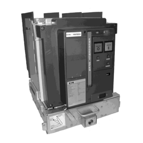
Eaton Magnum PXR User manual

Magnum PXR low voltage power circuit breakers
Technical product guide

DISCLAIMER OF WARRANTIES AND LIMITATION OF LIABILITY
The information, recommendations, descriptions and safety notations in this document are based on Eaton Corporation’s
(“Eaton”) experience and judgment and may not cover all contingencies. If further information is required, an Eaton sales
office should be consulted. Sale of the product shown in this literature is subject to the terms and conditions outlined in
appropriate Eaton selling policies or other contractual agreement between Eaton and the purchaser.
THERE ARE NO UNDERSTANDINGS, AGREEMENTS, WARRANTIES, EXPRESSED OR IMPLIED, INCLUDING
WARRANTIES OF FITNESS FOR A PARTICULAR PURPOSE OR MERCHANTABILITY, OTHER THAN THOSE SPECIFICALLY
SET OUT IN ANY EXISTING CONTRACT BETWEEN THE PARTIES. ANY SUCH CONTRACT STATES THE ENTIRE
OBLIGATION OF EATON. THE CONTENTS OF THIS DOCUMENT SHALL NOT BECOME PART OF OR MODIFY ANY
CONTRACT BETWEEN THE PARTIES.
In no event will Eaton be responsible to the purchaser or user in contract, in tort (including negligence), strict liability or
other-wise for any special, indirect, incidental or consequential damage or loss whatsoever, including but not limited to
damage or loss of use of equipment, plant or power system, cost of capital, loss of power, additional expenses in the use
of existing power facilities, or claims against the purchaser or user by its customers resulting from the use of the informa-
tion, recommendations and descriptions contained herein. The information contained in this manual is subject to change
without notice.

Table of contents
MAGNUM PXR PRODUCT GUIDE PA013006EN September 2022 www.eaton.com iii
1 Overview of the Magnum PXR low voltage circuit breaker
Breaker overview......................................................6
Magnum PXR (UL standards) ............................................7
Universal family features ................................................9
PXR overview ........................................................9
Motorized remote racking (MR2). . . . . . . . . . . . . . . . . . . . . . . . . . . . . . . . . . . . . . . . . 11
Construction characteristics ............................................11
Rigid frame housing ................................................11
Three piece construction ............................................11
Two-step stored energy mechanism ...................................11
Unsurpassed performance design .....................................11
Value-added features ...............................................12
Front cover features ................................................12
Front cover details .................................................13
Breaker internal features ............................................14
Breaker secondary .................................................15
Breaker mounting configurations ......................................19
Cassettes (available designs) .........................................19
Design configuration flexibility ..........................................20
2 Technical data and ratings
Sizes, dimensions, weights, and configurations .............................22
Magnum PXR ANSI breaker family ratings .................................23
Technical data sheet ..................................................24
Catalog builder.......................................................26
Breaker ..........................................................26
Cassette .........................................................28
Nameplate identification and markings ....................................29
High performance interrupting and withstand levels .........................29
Continuous current ratings .............................................29
3 PXR trip unit and communication modules
Overview of PXR electronic trip units ........................................30
Standards and certifications ............................................30
PXR protection settings/features.........................................30
PXR protection .........................................................31
PXR trip unit module catalog numbers .......................................32
Magnum DS digitrip to Magnum PXR equivalency..............................32
Trip unit wiring ..........................................................33
Common PXR unit features................................................34

iv
Table of contents
MAGNUM PXR PRODUCT GUIDE PA013006EN September 2022 www.eaton.com
3 PXR trip unit and communication modules (continued)
Measurement ............................................................ 35
Table of metering data in the PXR 20 and PXR 25 ............................. 35
Mechanical trip flag pop-out indicator ....................................... 36
Bell alarm/overcurrent trip switch (OTS) ..................................... 36
Making current release .................................................. 36
Fixed internal instantaneous override trip .................................... 36
Long time memory (LTM) ................................................ 36
Over temperature trip ................................................... 36
Arcflash reduction maintenance system........................................ 37
Power Xpert Protection Manager software (PXPM) ............................... 38
4 Magnum PXR accessories
Overview ................................................................ 39
Plug-in electrical accessories................................................. 39
Shunt trip (ST) ......................................................... 39
Spring release and latch check switch....................................... 40
Undervoltage release ................................................... 41
Auiliary switch ......................................................... 42
Internal electrical accessories ................................................ 42
Mechanical trip flag pop-out indicator ....................................... 42
Overcurrent trip switch (bell alarm) ......................................... 43
Motor operator ........................................................ 43
Typical Magnum breaker control circuit diagram............................... 44
Mechanical accessories..................................................... 45
Operations counter ..................................................... 45
Off key lock ........................................................... 45
Cassette lock .......................................................... 45
Pushbutton and prevent close cover ........................................ 45
Lock-off cover ......................................................... 46
Cassette safety shutters ................................................. 46
Cassette cell switch. . . . . . . . . . . . . . . . . . . . . . . . . . . . . . . . . . . . . . . . . . . . . . . . . . . . . 46
Door escutcheon ....................................................... 47
IP55 waterproof cover ................................................... 47
Mechanical interlock .................................................... 47
Accessories and peripheral devices ........................................... 49
Levering tool .......................................................... 49
Motorized remote racking device (MR2) ..................................... 49
Magnum external remote racking device (MRR1000)........................... 49
Universal remote power racking system (Type RPR-2) .......................... 50
Lifting yoke and floor lifting device ......................................... 50
Test cabinet ........................................................... 50
Auxiliary power module.................................................. 50
Secondary injection testing via PXPM ...................................... 51
Time delay undervoltage module .......................................... 52

Table of contents
MAGNUM PXR PRODUCT GUIDE PA013006EN September 2022 www.eaton.com v
4 Magnum PXR accessories (continued)
Communication accessories ...............................................53
Modbus_RTU communications ..........................................53
CAM (communications adapter modules)..................................53
Communication configurations ..........................................54
5 Magnum PXR applications
Transformer breakers.....................................................55
Bus sectionalizing (tie) breakers ............................................55
Generator breakers ......................................................55
Resistance welding ......................................................55
Zone selective interlocking ................................................57
ZSI testing ..........................................................58
Low voltage high resistance ground fault sensing ..............................59
Ground fault provisions and protective schemes ...............................59
Phasing on double-wide application .........................................61
AABBCC or NNAABBCC phasing ........................................61
ABCABC or NABCNABC phasing ........................................61
Power system coordination................................................61
6 Maintenance, tesing, and operating conditions
Maintenance schedules...................................................62
Normal maintenance ..................................................62
Increased maintenance ................................................62
Breaker health monitoring .................................................63
Testing ................................................................64
Tools for troubleshooting..................................................64
Event summaries.....................................................64
Waveform capture ....................................................64
Usual service conditions ..................................................65
Normal environmental conditions ........................................65
Ambient temp and thermal derating tables ................................65
Altitude factors ......................................................66
Test bus configuration .................................................66
Recommended electrical clearances......................................67
Recommended enclosure size/ventilation..................................67
Condensation heaters in enclosures ......................................67

6
Overview of the Magnum PXR low voltage circuit breaker
MAGNUM PXR PRODUCT GUIDE PA013006EN September 2022 www.eaton.com
1Magnum family
overview
Breaker overview
Eaton’s Magnum low
voltage power circuit
breakers have set industry
standards for decades
for the global market. The
broad and powerful circuit
breaker offering provides
comprehensive solutions
to meet and/or exceed
the unique and wide-
ranging requirements of
today’s power distribution
systems.
This innovative circuit
breaker offering is
designed for ultimate
performance, custom
configuration, and applica-
tion flexibility. Magnum
circuit breakers combine
many years of successful
circuit breaker protection
experience with the latest
technological advances in
circuit breaker, trip unit,
and communications
performance.
Ever since introducing
the first microprocessor-
based trip unit, Eaton has
advanced the technology
with its versatile family
of Digitrip RMS trip units
designed exclusively for
Magnum circuit breakers.
With the introduction of
the new Power Xpert™
Release (PXR) trip units
Eaton has again advanced
the technology for circuit
protection, safety and ease
of use. The new optional
integral rack in and rack
out mechanism (MR2)
provides higher levels of
safety for workers.
Customers now have the
capability of providing
an electrical distribution
system with:
•Superior flexible and
programmable protec-
tion and coordination
•Advanced warning
capabilities
•New capabilities from
data and analytics in
system health,
diagnostics, monitoring,
and communications
•Simplified setup and
testing via USB
connection and Power
Xpert Protection
Manager (PXPM)
software
Eaton’s Magnum family
addresses the needs of
a wide range of varying
global application
requirements. You will
find product details,
dimensional information,
maintenance recom-
mendations, and more
when you take a closer
look within this Magnum
product guide. Magnum
consists of four products.
Each provides specific
ratings, features and
approvals to optimize
performance in concert
with the application.
For more information and
resources, visit
Eaton.com/magnumpxr
Figure 1. Standard frame Magnum PXR breaker and
cassette

7
Overview of the Magnum PXR low voltage circuit breaker
MAGNUM PXR PRODUCT GUIDE PA013006EN September 2022 www.eaton.com
1
Magnum PXR
(UL standards)
Magnum PXR low voltage
power circuit breakers
are UL listed, designed,
tested and certified to all
applicable ANSI, NEMA,
UL, and IEEE standards.
Specifically, the circuit
breakers meet or exceed
the following:
•UL 1066
•ULC 1066
•ANSI C37.13
•ANSI C37.16
•ANSI C37.17
•ANSI C37.50
In addition, Magnum PXR
is suitable for use in UL
1558 “Certified Magnum
PXR low voltage metal
enclosed switchgear”
Product family
characteristics:
•Up to 635 Vac operating
voltage
•Up to 100 kA
interrupting ratings
•Up to 100 kA short time
withstand ratings
•100-6000A continuous
current ratings
•Three- and four-pole
configurations
•Fixed and drawout
Figure 2. Double narrow frame Magnum PXR breaker

8
Overview of the Magnum PXR low voltage circuit breaker
MAGNUM PXR PRODUCT GUIDE PA013006EN September 2022 www.eaton.com
1The Magnum PXR family
(identified by a medium
gray front cover) of low
voltage power circuit
breakers is ANSI designed,
tested and certified to
UL 1066. UL 1066 Listed
type PXR low voltage
power circuit breakers
are intended to provide
main and feeder circuit
protection in accordance
with UL1066 “Standard
for Safety for Low-Voltage
AC and DC Power
Circuit Breakers Used in
Enclosures”. UL and ANSI
test certifications Magnum
PXR meets or exceeds the
applicable ANSI, NEMA®,
UL, and IEEE standards.
Specifically, the circuit
breakers meet or exceed
the following:
•ANSI C37.13 “Low
Voltage AC Power
Circuit Breakers Used in
Enclosures”
•ANSI C37.16 “Preferred
Ratings, Related
Requirements,
and Application
Recommendations for
Low Voltage Power
Circuit Breakers and AC
Power Circuit Breakers”
•ANSI C37.17 “Trip
Devices for AC and
General-Purpose DC
Low Voltage Power
Circuit Breakers”
•ANSI C37.50 “Test
Procedures for Low
Voltage AC Power
Circuit Breakers Used in
Enclosures”
•UL 1066 “Standard for
Low Voltage AC and DC
Power Circuit Breakers
Used in Enclosures”
Magnum PXR has proven
performance in Eaton
manufactured switchgear
with the following test
certifications:
•UL 1558 “Certified
Magnum DS Low
Voltage Metal-Enclosed
Switchgear”
•UL 1008 “Standard for
Safety Transfer Switch
Equipment”
•C22.2 No. 31-14
Switchgear Assemblies
Approvals and marks:
•UL listed: Magnum PXR
Breaker UL File No.
E52096 and Cassette
UL File No.E204565
•ABS (American Bureau
of Shipping) Type Listed
Certificate Number
04-HS422844A-DUB
•Additional Magnum PXR
approvals and certifi-
cates can be found on
www.eaton.com
Figure 3. Magnum PXR breaker frame sizes

9
Overview of the Magnum PXR low voltage circuit breaker
MAGNUM PXR PRODUCT GUIDE PA013006EN September 2022 www.eaton.com
1
Universal family features
Each family has its own unique performance and features,
each Magnum breaker boasts a wide array of common
design elements. These common design elements deliver
proven performance with expanded capabilities, no matter
which product family is applied. To fulfill the latest market
needs with proven reliability and performance, Magnum is
the clear choice for low voltage applications.
PXR overview
The Power Xpert Release (PXR) electronic trip units for the
Magnum PXR low-voltage power air circuit breakers are
Eaton’s latest innovation in circuit protection technology.
They are designed to help you simplify your communica-
tions, enhance your protection, proactively monitor breaker
health, and support your energy metering. The Eaton PXR
trip unit platform enables you to easily change set points,
test and configure circuit breakers, and meter energy and
power information.
PXR 20 (Current metering with optional communications)
•USB connectivity and onboard testing hardware via
Power Xpert Protection Manager (PXPM) software
eliminates additional test kits or soft tests required by
competitors.
•Cause of trip indication via PXPM software and LED
indication allows faster troubleshooting and prevents
downtime.
•A fully adjustable trip unit with LSI and LSIG protection
capabilities. This trip unit offers a wider range of
settings and more advanced features than ever
before at this level, including current metering (0.5%
accuracy), programmable relays, and optional embedded
communications to enable seamless integration into
control and communication systems.
•The PXR 20 also offers cutting-edge safety features
like the Arcflash Reduction Maintenance System™ and
Zone Selective Interlocking with new testing and status
indication features, and input signal detection indication.
PXR 25 (High accuracy power and energy metering
capable of class 1 metering accuracy with standard
communications)
•Enhances the capabilities of the PXR 20 with a fully
programmable trip unit with full metering, enhanced
adjustability, additional protections, and standard
communications.
•Offers more functionality than ever before in a circuit
breaker trip unit. 1% accuracy for energy readings
(voltage 0.5% and current 0.5%), coupled with the
option for multiple communication protocols and
embedded programmable relays, making this the
ultimate example of an intelligent node in a power
distribution system.
•Leverage the capabilities of this product to eliminate
meters and other components from the system,
making the power distribution system cost effec-
tive and smaller, with increased intelligence and
connectivity.
10
Overview of the Magnum PXR low voltage circuit breaker
MAGNUM PXR PRODUCT GUIDE PA013006EN September 2022 www.eaton.com
1A range of trip unit options, coupled with field replaceable trip units, enables compatibility with global requirements and
allows upgrade from the most basic protective device to a high end, intelligent node in a power system.
The Power Xpert Release trip units provide cost savings
and advanced functionality through the Power Xpert
Protection Manager (PXPM) interface. This intuitive user
interface allows for simple trip unit set up and program-
ming, real-time reporting of power and energy metering,
as well as the ability to check critical performance metrics,
to meet your application needs while decreasing main-
tenance and in-field testing time. The testing features
and functionality, which can be run through a personal
computer, offers savings through labor hour reduction and
avoiding the need for expensive proprietary testing kits.
Ultimate control and data are at your fingertips:
•Set Point Configuration: Allows direct-to-trip unit or
offline set up, including duplication of settings between
units for soft settings only (dial settings must still be set
manually).
•Control Mode: Capture waveforms, reset the trip unit
or set the date/time.
•Test Mode: Run secondary injection tests and create
test reports.
•Real-Time Data: Provides information regarding all
status and metered data direct from the trip unit.
•Event Summaries: Stores up to 200 events, detailed
information on the most recent (10) trip and (10) alarm
events, and time adjustments to the real-time clock.
•Reports: Allows for the formatting and printing of real
time data and of performed secondary injection tests.
Figure 4. Power Xpert Release 20 electronic trip unit

11
Overview of the Magnum PXR low voltage circuit breaker
MAGNUM PXR PRODUCT GUIDE PA013006EN September 2022 www.eaton.com
1
Motorized remote racking (MR2)
Eaton’s integral motorized remote racking (MR2) provides
a means of remotely racking any Magnum drawout circuit
breaker. The integral racking system can also be utilized
to open and close the circuit breaker remotely, using
local or remote controls. The addition of an MR2 system
helps mitigate electrical arc flash exposure by allowing the
operator to work from outside the arc flash boundary. For
more information on Eaton’s integral motorized remote
racking (MR2), see the MR2 section in Accessories and
Peripheral Devices.
Construction characteristics
From the inside out, safety is of paramount importance
with special attention given to live parts insulation
and segregation between phases. Careful selection of
materials, meticulous assembly, rigorous testing, and
unsurpassed experience make Magnum a proven reliable
product.
Rigid frame housing
Magnum circuit breakers use a rigid frame housing
construction of durable engineered thermoset composite
resins.
•Strong and lightweight material with strength to weight
ratio twice that of steel. Proven able to withstand high
dynamic and thermal stresses.
•Excellent dielectric characteristics, resisting arc tracking.
Three piece construction
The 3-piece construction (rear housing, front housing,
and cover) provides support while isolating and insulating
power conductors.
•The 2-piece case encloses the current paths and arc
chambers. Chambers act to channel arc gases up and
out during interruption.
•The operating mechanism and accessories sit on
the front of the case. Only the insulating front cover
needs to be removed to access mechanism and/or
accessories.
•The operating mechanism achieves a longer life as a
result of reduced frame deflection during operation
along with stiff component mounting.
Two-step stored energy mechanism
Magnum circuit breakers are equipped with a true 2-step
stored energy mechanism.
•Closing springs can be charged manually or electrically.
•5 to 7 downward strokes on the charging handle
completes charging process.
•Mechanism provides for a complete OPEN – CLOSE –
OPEN cycle.
Unsurpassed performance design
The performance characteristics of the Magnum breaker
are attributed in many ways to a C-loop current path
design and movement. Contact fingers perform both the
main and arcing contact functions on different parts of the
same finger. A complete movable contact assembly is a
combination of several single contact fingers. The exact
number of contact fingers required depends upon the
frame size and interrupting rating of the breaker. Braided
connectors (flexible shunts) are used to attach each
contact finger. The result is an efficient and uniquely func-
tional main contact system with the following advantages:
•Eliminates bolted joints reducing hot spots.
•Reduced mounting space for primary contacts.
•Smaller and lighter operating mechanism for longer life.
•Higher interrupting and short time (withstand) ratings.
•5-cycle or less closing.
•Improved contact material.
•Contact wear indicator for each primary contact
structure.
•Individually removable arc chambers insulate/isolate
each pole.
•Ability to withstand high dynamic and thermal stresses.

12
Overview of the Magnum PXR low voltage circuit breaker
MAGNUM PXR PRODUCT GUIDE PA013006EN September 2022 www.eaton.com
1Value-added features
Magnum provides numerous other internal and external
features that further enhance the reliability, maintenance
and safety of this industry leading product offering. Several
additional common features are highlighted below. See
the following sections on PXR trip unit and communication
modules and Magnum PXR Accessories for more in-depth
information.
•Available Arcflash Reduction Maintenance System™
optional on PXR 20 and standard on PXR 25 trip units,
to lower personnel risk and PPE levels in the arcflash
boundary.
•Field installable trip units and accessories.
•Mechanical and electrical anti-pump features.
•Easily removable arc chutes for inspection.
•Common accessories for all frame sizes (electrical and
mechanical).
•Automatic drawout primary shutters.
•Conveniently located finger proof secondary contacts.
•Will accommodate a variety of primary terminal types/
configurations.
•Fungus-proof breaker housings.
Front cover features
•The front cover contains a conveniently accessible
operating panel with clear words and symbols identify-
ing functions while guiding operations. This intuitive
interface permits an authorized operator to proceed with
confident control and precise configurations.
•Prominently displayed nameplate provides important
circuit breaker specific information. Magnum breakers
must be applied within their nameplate ratings.
•Some field installable accessories are easily identified
by name and rating through viewing windows. They are
the shunt trip, spring release and undervoltage release.
•Optional padlockable cover limits access to “CLOSE”
and “OPEN” pushbuttons
•Complete access to the “CLOSE” pushbutton can be
prevented with optional prevent close cover.
Figure 5. Nameplate breaker information
Figure 6. Accessory viewing windows
Figure 7. Optional padlockable cover

13
Overview of the Magnum PXR low voltage circuit breaker
MAGNUM PXR PRODUCT GUIDE PA013006EN September 2022 www.eaton.com
1
Front cover details
Controls and indicators are functionally grouped on the
breaker faceplate to optimize the user interface, visibility
and ease of use. The modern, through-the-door design
delivers maximum safety and convenience.
1. Accessory Viewing Windows for:
•Shunt Trip attachment (ST)
•Spring Release device (SR)
•Undervoltage Release device (UVR) or second ST
2. PXR trip units protected by a clear cover that gives
provisions to wire tie the cover shut for extra
security
3. Red Mechanical Trip Flag Pop-out Indicator
(Optional)
•Interlocked Indicator Requiring Manual Reset is also
available
4. Contact Status Indicators:
•OPEN (Green)
•CLOSED (Red)
5. Spring Status Indicators:
•CHARGED (Yellow)
•DISCHARGED (White)
6. OPEN Pushbutton (Red)
7. CLOSE Pushbutton (Green)
8. Manual Spring Charging Handle: to charge stored
energy springs
9. Mechanical Operations Counter (Optional)
10. Key Off Lock (Optional, not shown)
11. Padlockable Levering Device Shutter: for drawout
breakers only
12. Color-Coded Position Indicator for drawout
breakers:
•CONNECT (Red)
•TEST (Yellow)
•DISCONNECT (Green)
Figure 8. Magnum PXR front cover details
12 3
4
7
5
8
9
10
12
11
6

14
Overview of the Magnum PXR low voltage circuit breaker
MAGNUM PXR PRODUCT GUIDE PA013006EN September 2022 www.eaton.com
1Breaker internal and rear view features
Magnum circuit breakers are designed for ease of access
for inspection, modification and maintenance at the point
of use. The breaker front cover is easily removed with
four captive bolts, revealing the modular internal breaker
features.
1. Secondary terminal points for internal standardized
breaker wiring connections
2. Breaker accessory mounting deck with three posi-
tions for mounting:
•Shunt Trip device (ST)
•Spring Release device (SR)
•Undervoltage Release device (UVR) or second ST
3. PXR Trip Unit
4. Spring charging motor (optional) for electrically
charging the stored energy springs
5. Manual spring charging handle for manually charg-
ing the stored energy springs
6. Padlockable levering device shutter for drawout
breakers
7. Color-coded position indicator for drawout
breakers:
•CONNECT (Red)
•TEST (Yellow)
•DISCONNECT (Green)
8. Secondary contact block for connection to external
cell control wiring
9. Removable arc chute covers for easy access to
breaker main contacts
10. Primary finger cluster disconnecting contacts for
drawout breaker are mounted on the breaker
element for ease of access for inspection and
maintenance
ote:NSome competitors mount the primary finger
clusters inside the cell, requiring shutdown of the
switchgear for inspection and maintenance.
11. Rigid frame housing (thermoset composite resin)
providing increased strength and durability
Figure 9. Magnum PXR internal features
Figure 10. Magnum PXR rear view
3
4
8
9
1011
1
2
5
6
7

15
Overview of the Magnum PXR low voltage circuit breaker
MAGNUM PXR PRODUCT GUIDE PA013006EN September 2022 www.eaton.com
1
Breaker secondary
All of the electrical accessories internal to the breaker are
wired to the 84 point connector at the breaker secondary.
The terminal numbers for the internal accessories are
consistent across all breaker frames and mounting
options, and are labeled on the breaker secondary
connector.
To facilitate customer control wiring in the field, both fixed
mounted breakers and drawout cassettes are available
with secondary terminal blocks that will be mounted above
the breaker or cassette. These are 6-point terminal blocks
with finger proofed hinged covers. These terminal blocks
are rated 30A, and will accept bare wire, ring or spade
terminals for wire size ranges of #22–#10.
Fixed mounted breakers and drawout cassettes can be
ordered with or without secondary wiring. For breakers
and cassettes ordered with secondary wiring the layout of
the 6-point terminal blocks depends on the breaker frame.
Breakers and cassettes ordered without secondary wiring
will not include any 6-point terminal blocks.
Standard, double narrow, and double frame cassettes are
available with two terminal block options:
•Fully wired: includes 12 terminal blocks for a total of 72
points.
•Required and commonly wired: includes 8 terminal
blocks for the most commonly used 48 points.
Narrow frame cassettes are available with one terminal
block option:
•Fully wired: includes 8 terminal blocks for the most
commonly used 48 points.
Narrow, standard, double narrow, and double frame fixed
mounted breakers are available with one terminal block
option:
•Required and commonly wired: includes 8 terminal
blocks for the most commonly used 48 points.
Refer to Table 1 for more details on what points are
harnessed up to the 6-point terminal blocks. Any point
not harnessed from the breaker secondary to the 6-point
secondary blocks can be directly accessed at the breaker
secondary using ampere pins. For more information, see
breaker user manual, MN13016EN.
Terminal block extension brackets are available for drawout
cassettes. One bracket can be mounted on each side of
the cassette and each bracket provides 3 additional 6-point
terminal blocks. These can be used to land cell switch
wires or breaker accessory wires not available in the two
terminal block layouts shown in Figures 12 and 13.
Figure 11. Secondary connector on cassette

16
Overview of the Magnum PXR low voltage circuit breaker
MAGNUM PXR PRODUCT GUIDE PA013006EN September 2022 www.eaton.com
1
Switchgear providers including Eaton assemblies may customize to other terminal configurations. See Table 1 for
terminal to accessory assignment.
Figure 12. 12 terminal block option
Figure 13. 8 terminal block option
Figure 14. Secondary terminal layout
ote:NNot all breaker terminal points are available with the secondary terminal block configurations.
a Not included in 48 point secondary terminal block configuration.
b Not included in 72 point secondary terminal block configuration.

17
Overview of the Magnum PXR low voltage circuit breaker
MAGNUM PXR PRODUCT GUIDE PA013006EN September 2022 www.eaton.com
1
Table 1. Terminal to accessory assignment
PXR point
position PXR point
name General description Function Individual point description
C1 O1NO
Overcurrent trip switch 1 Indicates when breaker opens via the trip unit
Overcurrent trip switch 1 make
C2 O1C Overcurrent trip switch 1 common
C3 O1NC Overcurrent trip switch 1 break
C4 O2NO
Overcurrent trip switch 2 Indicates when breaker opens via the trip unit
Overcurrent trip switch 2 make
C5 O2C Overcurrent trip switch 2 common
C6 O2NC Overcurrent trip switch 2 break
C7 G1 External ground fault source / zero
sequence sensor
External ground fault sensor trip unit input for source /
zero sequence sensing
Ground fault sensor lead 1
C8 G2 Ground fault sensor lead 2
C9 SC Closing spring charged Closed when spring is fully charged Spring charged switch output
C10 RY1
Trip unit relays
Alarm 1 - Default setting: Maintenance mode active
(ARMS trip units) or Health warning (non-ARMS trip
units)
Configurable relay 1
C11 RY2
Alarm 2 - Default setting: Ground fault trip (LSIG trip
units) or High load alarm (LSI trip units) Configurable relay 2
C12 RY3 Alarm 3 - Default setting: Any current protection trip Configurable relay 3
C13 RYC Relay common Configurable relay common
C14 +24V Trip unit auxiliary power supply input External trip unit power Auxilliary power supply positive
C15 0V Auxilliary power supply common
C16 NExternal neutral current sensor Connect to the external neutral current sensor, jumper if
not needed and in a 4-pole breaker
Neutral current sensor lead 2
C17 N• Neutral current sensor lead 1 (N DOT)
C18 MM Remote maintenance mode enable Enable maintenance mode via a remote switch Maintenance mode signal
C19 ZI ZSI - Input Connect to other ZSI enabled breakers in the system
(maximum length of 25 meters (75 feet) using AWG #22
wire)
Zone selective interlock input
C20 ZC Trip Unit Circuit Common Zone selective interlock common
C21 ZO ZSI - Output Zone selective interlock output
C22 MBA
Modbus RTU Modbus RTU communication onboard trip unit
Non-Inverting (+) Signal
C23 MBB Inverting (-) Signal
C24 MBG RS485 ground
C25 aCOMO Future
C26 aCOMC Future
C27 aCM3
Trip unit communication adapter
module (CAM) connections Connect to a CAM
RX+ / CMM1
C28 aCM4 RX- / CMM2
C29 aCM1 TX+ / CMM3
C30 aCM2 TX- / CMM4
C31 aFuture
C32 aFuture
C33 aFuture
C34 aFuture
C35 aFuture
C36 aFuture

18
Overview of the Magnum PXR low voltage circuit breaker
MAGNUM PXR PRODUCT GUIDE PA013006EN September 2022 www.eaton.com
1PXR point
position PXR point
name General description Function Individual point description
C37 a b 9NC
Auxilliary switch 3 Indicates breaker open / closed status
Aux switch 9 b
C38 a b 9NO Aux switch 9 a
C39 a b 9C Aux switch 9 common
C40 a b 10NC Aux switch 10 b
C41 a b 10NO Aux switch 10 a
C42 a b 10C Aux switch 10 common
C43 a b 11NC Aux switch 11 b
C44 a b 11NO Aux switch 11 a
C45 a b 11C Aux switch 11 common
C46 a b 12NC Aux switch 12 b
C47 a b 12NO Aux switch 12 a
C48 a b 12C Aux switch 12 common
C49 VN Voltage divider board neutral input Connection for system neutral voltage (3-pole breakers
only, no connection in a 4-pole breaker)
VDB neutral
C50 ST+ Shunt trip Remote opening Shunt trip positive
C51 ST- Shunt trip negative
C52 SR+ Spring release Remote closing Spring release positive
C53 SR- Spring release negative
C54 M+ Motor operator Motor positive
C55 M- Motor negative
C56 UV+ Undervoltage release Remote opening UVR positive
C57 UV- UVR negative
C58 LNO
Latch check switch Checks breaker ready to close status
Latch check make
C59 LC Latch check common
C60 LNC Latch check break
C61 1NC
Auxilliary switch 1 Indicates breaker open / closed status
Aux switch 1 b
C62 1NO Aux switch 1 a
C63 1C Aux switch 1 common
C64 2NC Aux switch 2 b
C65 2NO Aux switch 2 a
C66 2C Aux switch 2 common
C67 3NC Aux switch 3 b
C68 3NO Aux switch 3 a
C69 3C Aux switch 3 common
C70 4NC Aux switch 4 b
C71 4NO Aux switch 4 a
C72 4C Aux switch 4 common
C73 5NC
Auxilliary switch 2 Indicates breaker open / closed status
Aux switch 5 b
C74 5NO Aux switch 5 a
C75 5C Aux switch 5 common
C76 6NC Aux switch 6 b
C77 6NO Aux switch 6 a
C78 6C Aux switch 6 common
C79 7NC Aux switch 7 b
C80 7NO Aux switch 7 a
C81 7C Aux switch 7 common
C82 8NC Aux switch 8 b
C83 8NO Aux switch 8 a
C84 8C Aux switch 8 common
a Not included in 48 point secondary terminal block configuration.
b Not included in 72 point secondary terminal block configuration.
Table 1. Terminal to accessory assignment (continued)

19
Overview of the Magnum PXR low voltage circuit breaker
MAGNUM PXR PRODUCT GUIDE PA013006EN September 2022 www.eaton.com
1
Breaker mounting configurations
Magnum circuit breakers are available in both fixed and
drawout configurations; however, in a small number
of instances, only some breakers are available in fixed
configuration.
Fixed mounting
Magnum circuit breakers can be fixed mounted.
The breaker bolts directly to the enclosure main bus,
which allows for efficient current transfer under loaded
conditions. Metal mounting feet are provided as a
standard feature for use in securely bolting the breaker to
the enclosure. Fixed circuit breaker construction is simple
and economic because there are no drawout system
components. A fixed circuit breaker is supplied with
horizontal, pre-drilled primary terminal pads for terminating
the breaker to the bus.
ote:NOptional vertical primary adapters are available to
accommodate different bus configurations. See
Section 8 for diagrams with detailed dimensions.
Drawout mounting
A drawout circuit breaker is used in combination with a
cassette. The cassette provides for all the required drawout
features for both primary and secondary connections.
Mounting locations for cassette mounted cell switches,
primary safety shutters and various key interlocks are part
of the cassette design, to allow for customized customer
options. Refer to Section 8 for specific drawout circuit
breaker dimensions.
Cassettes – available styles
Narrow frame cassettes (for narrow frame and double narrow
frame breakers)
For narrow frame circuit breakers, there is one type of
cassette design, which uses horizontal stabs. Optional
bolt-on 90-degree adapters can be used to rotate the
cassette’s primary terminals to a vertical orientation as
required. The 4000A double narrow cassette is available
in this same design as well as a vertical interleaf design
which utilizes an interleaved style connection on the back
of the cassette. The 5000A double narrow utilizes this
same vertical interleaf cassette with additional bus (see
Special 5000A double narrow and 6000A double wide
runback section).
Standard frame cassettes (for standard frame and double
standard frame breakers)
For standard and double frame circuit breakers, there are
three cassette styles, all with vertical stabs available:
•Basic cassette with copper stabs: This cassette
comes with factory installed copper stabs/terminals on
the cassette.
Figure 15. Fixed mounting breaker
Figure 16. Drawout mounting breaker
Figure 17. Narrow frame cassettes
Figure 18. Standard frame cassette with copper stabs

20
Overview of the Magnum PXR low voltage circuit breaker
MAGNUM PXR PRODUCT GUIDE PA013006EN September 2022 www.eaton.com
1•Basic cassette without copper stabs: The basic
cassette can also be ordered without factory supplied
copper stabs/terminals. Ordering without stabs allows
the switchgear builder to integrate the cassette by using
their vertical busbars.
•Universal cassette: A set of flat pad terminals on the
rear of the cassette are provided. They can be adapted
to vertical or horizontal connection.
•Special 5000A double narrow and 6000A double
wide runback: Eaton’s 5000 A DN and 6000 A DW
are provided with the run back bus. The run back bus
connects the back of the cassette to the manufac-
turer’s riser bus in their switchgear. The run back bus
is shipped separately for ease of installation into the
manufacturer’s switchgear along with instructions on
how to properly install. There are two options of run
back bus available; 1) Main breaker positions and 2)
Tie breaker positions as shown in the figure below.
The 5000 A DN cassette utilizes an interleaved style
connection on the back of the cassette to make
it easier to install standard bus bar thicknesses.
connects the back of the cassette to the manufac-
turer’s riser bus in their switchgear. The run back bus
is shipped separately for ease of installation into the
manufacturer’s switchgear along with instructions on
how to properly install. There are two options of run
back bus available; 1) Main breaker positions and 2)
Tie breaker positions as shown in the figure below.
Design configuration flexibility
The modular Magnum design affords customers the
opportunity to meet the increasingly complex require-
ments of modern distribution systems.
•Fixed mounting: Standard horizontally mounted
primary connections with vertical adapters available for
other bus configurations. Integral mounting feet firmly
secure the breaker in position.
Figure 19. Standard frame cassette without copper
stabs
Figure 20. Universal cassette
Figure 21. Tie breaker bus (left) and main breaker bus
(right)
Figure 22. Fixed mounting breaker
Other manuals for Magnum PXR
1
Table of contents
Other Eaton Circuit Breaker manuals

Eaton
Eaton CN13GN0 Manual

Eaton
Eaton xComfort CDAU-01/02 User manual

Eaton
Eaton RMQ-Titan M22-XLED Series Manual

Eaton
Eaton Ulusoy URING36 - LLF User manual

Eaton
Eaton B20B-VR Series User manual

Eaton
Eaton FRCdM-Type B Manual

Eaton
Eaton VCPW-HD User manual

Eaton
Eaton P-SOL20 Manual

Eaton
Eaton QSA400 Series Manual

Eaton
Eaton NZM2-XSRM-LR Manual

Eaton
Eaton T5B Series Manual

Eaton
Eaton Series NRX Manual

Eaton
Eaton DDC-250/2-SK Manual

Eaton
Eaton EASY256-HCI Manual

Eaton
Eaton PXS24 Series User manual

Eaton
Eaton ZB-XPLH Manual

Eaton
Eaton Digitrip OPTIM 750 User manual

Eaton
Eaton NZM3-XR Series Manual

Eaton
Eaton Power Defense IZMX16 Manual

Eaton
Eaton IZM32 User manual