manuals.online logo
Brands
  1. Home
  2. •
  3. Brands
  4. •
  5. Eaton
  6. •
  7. Circuit Breaker
  8. •
  9. Eaton Cutler Hammer C30CN Series User manual

Eaton Cutler Hammer C30CN Series User manual

1
HAZARDOUS VOLTAGE
Disconnect all power before working on equipment.
Electrical shock will cause severe injury or death.
TENSION DANGEREUSE
Coupez l’alimentation avant travailler sur le produit.
Electrocution peut causer de sévères blessures ou la mort.
Description
The Cutler Hammer C30CN Series is a magnetically operated
lighting contactor, and is available in both open and enclosed
forms. These contactors are field configurable for up to twelve
poles, with a maximum of eight normally closed “NC” poles.
Figure 1: Mechanically Held Contactor
1 MAIN BASE
1.1 Description
The base of the lighting contactor (see Figure 1) has provisions
to accept power poles at positions “1” to “6”. Provisions are
also provided for up to 2 “NO” and 2 “NC” auxiliary contacts.
1.2 Installation
1. Remove all packing material from the base and all the kits.
2. Contactor must be mounted in the vertical position on a
sturdy support.
3. Additional over-current protection may be required. Refer
to the National Electrical Code or local electrical code as
required.
4. Refer to Section 5.3 and Table D on page 3 for the wire
size and the required torque for the coil terminals.
2 POWER POLES: C320PRP1 & C320PRP2
2.1 Description
Power poles are available in both single pole (C320PRP1) and
double pole (C320PRP2) versions. A maximum of twelve
poles may be installed on the base. Positions “1” to “4” on the
base can be configured as either normally open “NO” or “NC”
while positions “5” and “6” can be configured as “NO” only.
2.2 Removal and Conversion of Power Poles
1. If installed ensure that all power is disconnected.
2. For multiple possible configurations of the power poles,
refer to Table A below.
Table A
3. Remove block by using a screwdriver to pull the clip as
shown (see Figure 2). Rotate block 180 degrees to convert
from NO to NC or from NC to NO and install per 2.3
below.
Figure 2
2.3 Installation of Power Poles
1. Check moving carrier to assure free movement
2. Install the block by sliding foot into slot; using a
screwdriver pull the clip, and position block onto base.
Release the clip.
3. Check for the lettering on the base. “NO” should be
visible if the power pole is assembled as normally open,
and “NC” should be visible if it is assembled as normally
closed (see Figure 3).
# of NC Contacts Desired (3)
Standard Catalog # C30CNE43A0
WARNING !
!
Main Base
NO Aux.
Contact
NC Aux.
Contact
# of NO Contacts Desired (4)
C30CN Lighting Contactor Series
Instruction Sheet Pub50765
Revision A Page 1 of 4
DEH
-
41043
ECR LT#10001
2
Figure 3
2.4 Wiring
Power poles can accept wires from #14 to #8 AWG (either
solid or stranded) as single or combination of two wires (refer
to Table B below for valid wire combination). Wire material
must be copper with a temperature rating of 75 degrees C.
Maximum tightening torque is 35 in-lbs.
8 AWG 10 AWG 12 AWG 14 AWG
Size Type
Stranded Stranded Solid Stranded Solid Stranded Solid
8 AWG Stranded X X X X X X X
Stranded X X X X X X X
10 AWG
Solid X X X X X X X
Stranded X X X X X X X
12 AWG
Solid X X X X X X X
Stranded X X X X X X X
14 AWG
Solid X X X X X X X
Table B
3 AUXILIARY CONTACTS: C320AMH1 & C320AMH2
3.1 Description
The auxiliary contact blocks are available in both single pole
(C320AMH1) and double pole (C320AMH2) versions.
Auxiliary contacts can be added on either side of the base (see
Figure 1). When added to the LEFT side of base, the auxiliary
block functions as “NO”, and when added to the RIGHT side
of base it functions as “NC”. Refer to section 4.3 for wiring.
4 CONTROL MODULE KITS
The base (electrically held) can be converted to a mechanically
held type by adding a control module kit.
IMPORTANT: The control module kits are for use with the
coils up to 277 VAC maximum. Use a control power
transformer for higher voltages.
Conversion from an electrically held to a mechanically held
type is possible by adding a “control module kit” to the base.
4.1 Description
Control module kits are available both for 2-wire and 3-wire
control with a wide range of control voltage inputs. Figure 4
shows the components in 2-wire control module kit. A 3-wire
kit includes an additional single-pole auxiliary contact block.
Refer to the Ordering Detail section for more information on
control module kits and control voltages available.
Figure 4
4.2 Installation
1. Disconnect all power and mount the control module on the
contactor as shown in Figure 1 (3-wire control type).
2. Mount the latch as shown in Figure 5.
Figure 5 – Caution: Once latch cover has been installed,
it may not be removed. Ensure latch is properly installed
prior to installing the latch cover.
3. Be sure the latch is firmly in place with the wire facing out
and the slot positioned with tab inserted.
4. Mount the latch cover as shown in Figure 5.
Caution: Once latch cover has been installed, it may not
be removed. Ensure latch is properly installed prior to
installing the latch cover.
5. For 2-wire control, the auxiliary contact block is
assembled to the right side of the base for “NC”.
6. Operate contactor manually, using manual operation tabs
(See Figure 5) on side, prior to installing cover to insure
correct installation.
IMPORTANT:Latch and electronic module must be used
together to ensure proper operation. Failure to do so will void
warranty.
4.3 Wiring
Control module’s and auxiliary contact block’s terminals can
accept a single wire from #22 to #12 AWG (either solid or
stranded). Maximum tightening torque required for the
control module’s terminals is 5 in-lbs. Auxiliary contact
block terminals can accept parallel conductor size
combinations utilizing torques identified in Table C.
Latch
Latch Cover
Electrical
Module
Aux.
Co
n
tact
Operation
T
ab
DEH
-
41043
ECR LT#10001
Instruction Sheet Pub50765
Revision A Page 2 of 4
3
Wire Combination Torque
#12 with #14 12 in-lbs
#14 with #16 12 in-lbs
#16 with #18 12 in-lbs
#16 with #20 12 in-lbs
#16 with #22 12 in-lbs
#18 with #22 10-12 in-lbs
#18 with #20 10-12 in-lbs
#20 with #22 7-12 in-lbs
Table C
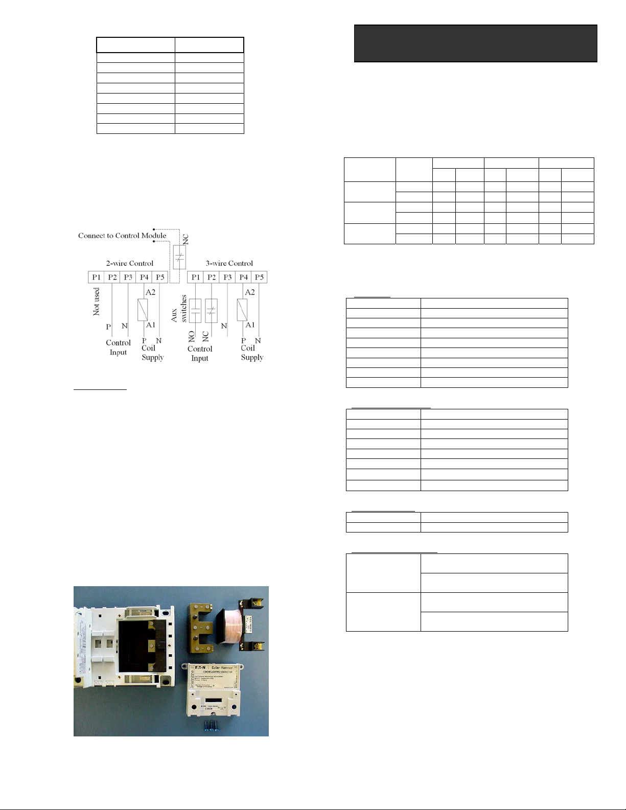
Follow the schematic (Figure 6) to wire the 2 and 3-wire
control modules.
Note: For 2-wire control, ensure the two wires coming from
the control module are connected across a NC auxiliary
contact.
Figure 6
5 COIL KITS
5.1 Description
A wide range of coils is available for both electrically held and
mechanically held lighting contactors. Refer to the Ordering
Detail section for more information about the coil kit catalog
numbers and voltages available.
Note: For mechanically held lighting contactor, only use coil
rated up to 277 VAC maximum. Use control power
transformer for higher voltages.
5.2 Installation
1. Disconnect all power. Replace and mount the coil on the
contactor as shown in Figure 7.
2. For mechanically held contactors, remove all wires from
the control module and remove the coil cover along with
control module.
5.3 Wiring
Coil terminal can accept wires from #18 AWG to #14 AWG
(either solid or stranded) as single or combination of two wires
(Refer to Table D below for valid wire combination). Wire
material must be copper with a temperature rating of 60 or 75
degrees C. Maximum tightening torque is 15 in-lbs.
Table D
Ordering Details
Coil Kits:
9-3242-7 24V 60Hz / 20V 50Hz Coil
9-3242-8 28V 60Hz / 24V 50Hz Coil
9-3242-1 115-120V 60Hz / 110V 50Hz Coil
9-3242-5 200-208V 60Hz Coil
9-3242-2 230-240V 60Hz / 220V 50Hz Coil
9-3242-6 265-277V 60Hz / 240V 50Hz Coil
9-3242-9 347V 60Hz Coil
9-3242-3 460-480V 60Hz / 440V 50Hz Coil
9-3242-4 575-600V 60Hz / 550V 50 Hz Coil
Control Module Kits:
C320MH2WT0 2 wire 24 VAC 60/50 Hz
C320MH2WA0 2 wire 110-120 VAC 60/50 Hz
C320MH2WH0 2 wire 200-277 VAC 60/50 Hz
C320MH2WT1 2 wire 12-24 VDC
C320MH3WT0 3 wire 24 VAC 60/50 Hz
C320MH3WA0 3 wire 110-120 VAC 60/50 Hz
C320MH3WH0 3 wire 200-277 VAC 60/50 Hz
C320MH3WT1 3 wire 12-24 VDC
Power Pole Kits:
C320PRP1 Single Power Pole
C320PRP2 Double Power Pole
Auxiliary Contact Kits:
Auxiliary Contact Block 1 NO when
mounted on left side of contactor.
C320AMH1 Auxiliary Contact Block 1 NC when
mounted on right side of contactor.
Auxiliary Contact Block 2 NO when
mounted on left side of contactor.
C320AMH2 Auxiliary Contact Block 2 NC when
mounted on right side of contactor.
Note:These instructions do not purport to cover all details or variations in
equipment nor provide for every possible contingency to be met in connection
with installation, operation, or maintenance. Should further information be
desired or should particular problems arise which are not covered sufficiently
or the Purchase’s purpose, the matter should be referred to Eaton e-Com
Technical Support. Toll free telephone (800) 356-1243.
Figure 7
# 14 AWG # 16 AWG # 18 AWG
Size Type
Solid Stranded Solid Stranded Solid Stranded
Solid X X X X X X
# 14 AWG Stranded X X X X X X
Solid X X X X X X
# 16 AWG Stranded X X X X X X
Solid X X X X X X
# 18 AWG Stranded X X X X X X
Instruction Sheet Pub50765
Revision A Page 3 of 4
DEH
-
41043
ECR LT#10001
4
Instruction Sheet Pub50765
Revision A Page 4 of 4
DEH
-
41043
ECR LT#10001
Wiring Diagrams
C30CNE Electrically Held Contactor
C30CNM Mechanically Held Contactor

This manual suits for next models

2

Other Eaton Circuit Breaker manuals

Eaton W-VACiMB User manual

Eaton

Eaton W-VACiMB User manual

Eaton IZM User manual

Eaton

Eaton IZM User manual

Eaton Power Defense IZMX40 Manual

Eaton

Eaton Power Defense IZMX40 Manual

Eaton CN13GN0 Manual

Eaton

Eaton CN13GN0 Manual

Eaton NHI-E Series Manual

Eaton

Eaton NHI-E Series Manual

Eaton 520 Manual

Eaton

Eaton 520 Manual

Eaton NZM2-4-XFI(30) Manual

Eaton

Eaton NZM2-4-XFI(30) Manual

Eaton DILMS80 Series Manual

Eaton

Eaton DILMS80 Series Manual

Eaton P-SOL60 Manual

Eaton

Eaton P-SOL60 Manual

Eaton Power Defense IZMX16 Manual

Eaton

Eaton Power Defense IZMX16 Manual

Eaton BRCAFLOFF Manual

Eaton

Eaton BRCAFLOFF Manual

Eaton Digitrip OPTIM 750 User manual

Eaton

Eaton Digitrip OPTIM 750 User manual

Eaton xComfort CDAU-01/02 User manual

Eaton

Eaton xComfort CDAU-01/02 User manual

Eaton Power Defense PDG5 Manual

Eaton

Eaton Power Defense PDG5 Manual

Eaton DSII Series Programming manual

Eaton

Eaton DSII Series Programming manual

Eaton Flex Shaft Manual

Eaton

Eaton Flex Shaft Manual

Eaton C Series Manual

Eaton

Eaton C Series Manual

Eaton NZM1-XHB-DA-OAG Manual

Eaton

Eaton NZM1-XHB-DA-OAG Manual

Eaton VCP-W Series User manual

Eaton

Eaton VCP-W Series User manual

Eaton Cutler-Hammer Digitrip 1150 User manual

Eaton

Eaton Cutler-Hammer Digitrip 1150 User manual

Eaton NZM-XCM Manual

Eaton

Eaton NZM-XCM Manual

Eaton NZM1-4-XFI300R Manual

Eaton

Eaton NZM1-4-XFI300R Manual

Eaton NZM2 User manual

Eaton

Eaton NZM2 User manual

Eaton AMH-4.76-VR User manual

Eaton

Eaton AMH-4.76-VR User manual

Popular Circuit Breaker manuals by other brands

OEZ AFD-16-1N Series Instructions for use

OEZ

OEZ AFD-16-1N Series Instructions for use

Siemens SDV-4A instruction manual

Siemens

Siemens SDV-4A instruction manual

AEG SF6 operating instructions

AEG

AEG SF6 operating instructions

Siemens-Allis LA-3200A instructions

Siemens-Allis

Siemens-Allis LA-3200A instructions

Rockwell Automation 189-CL1 Series quick start guide

Rockwell Automation

Rockwell Automation 189-CL1 Series quick start guide

Bticino Megabreak 2500 installation manual

Bticino

Bticino Megabreak 2500 installation manual

Siemens 3VA9603-0JJ25 operating instructions

Siemens

Siemens 3VA9603-0JJ25 operating instructions

ABB SACE Emax 2 manual

ABB

ABB SACE Emax 2 manual

Siemens SIRIUS 3RA1.5 operating instructions

Siemens

Siemens SIRIUS 3RA1.5 operating instructions

Vimar ELVOX 40636 instruction sheet

Vimar

Vimar ELVOX 40636 instruction sheet

brennenstuhl BDI-S 30 V2 Directions for use

brennenstuhl

brennenstuhl BDI-S 30 V2 Directions for use

Murrelektronik 85065 operating instructions

Murrelektronik

Murrelektronik 85065 operating instructions

Siemens SENTRON 3WA1 manual

Siemens

Siemens SENTRON 3WA1 manual

Siemens 5SL60 MC Series operating instructions

Siemens

Siemens 5SL60 MC Series operating instructions

Larson Electronics MPD CB-SF-489 Series installation manual

Larson Electronics

Larson Electronics MPD CB-SF-489 Series installation manual

Siemens Sentron 3VA9157-0FK Series operating instructions

Siemens

Siemens Sentron 3VA9157-0FK Series operating instructions

Siemens SION operating instructions

Siemens

Siemens SION operating instructions

Siemens 3VA9980-0VL 0 Series operating instructions

Siemens

Siemens 3VA9980-0VL 0 Series operating instructions

manuals.online logo
manuals.online logoBrands
  • About & Mission
  • Contact us
  • Privacy Policy
  • Terms and Conditions

Copyright 2025 Manuals.Online. All Rights Reserved.