Installation Instructions
Item:
Connect-AllMountingBlockAssembliesCat.No.
MB9301PDFrame,MBR9302RDFrame,MM9301and
MM9302PMFrame.
ForUseWith:
PDFrameTypesPD6,HPD6,PXD6,HPXD6and
CPD6CircuitBreakers. RDFrameTypesRD6,HRD6,
RXD6,HRXD6andCRD6CircuitBreakers. PMFrame
TypesPM6andPMKCircuitBreakers. PXD6andRXD6
MoldedCaseSwitches.SPD6,SHPD6andSCPD6
ElectronicCircuitBreakers.
Page
1of2
Pc.No.
73632A00
HazardousVoltage.
Will cause death or serious
injury
Turn off and lock out all power
supplying this device before
removing cover(s) or device and
while cover(s) are removed.
Replace the covers and shields
before power supplying this device
is turned on.
NOTE:This instruction outlines the recommended
installationprocedure.
Mounting of Connect-All Mounting Block
Assembly
CatalogNumbers:MB9301,MBR9302,MM9301,MM9302
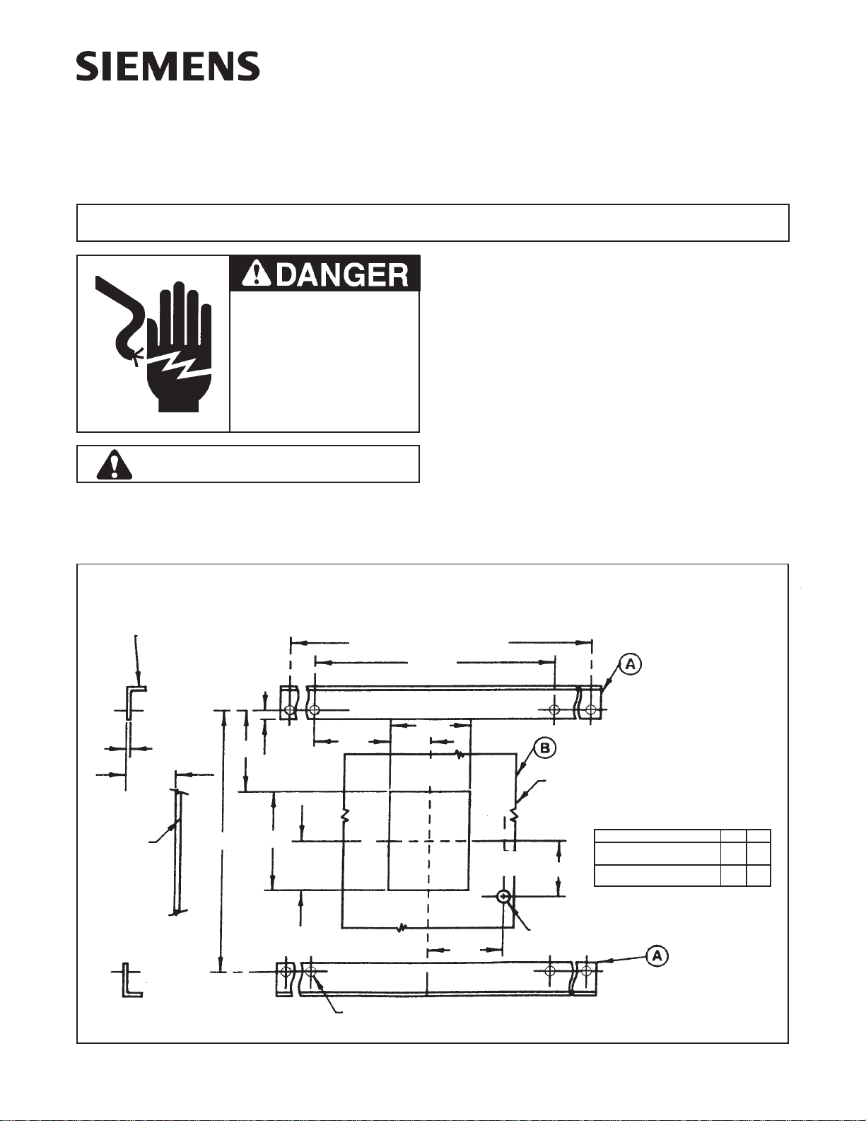
1. Provide suitable mounting supports (ItemA) and drill
holesper figure 1.
(Recommendeduseof 1-3/8 x 7/8 x 3/16 steel angle)
2. Provide cut out for breaker escutcheon in front plate
(Item B, Fig. 1).
NOTE: Refer to Figure 2 for Cat.No. MB9301 and
MM9301.Refer to Figure 3 for Cat.No. MBR9302 and
MM9302. Remove four 3/8 X 1-1/2" hex headbolts,
nutsand washers (ItemC,Fig. 2 & 3)andre-use them
to mount pan-and-block assembly to support angles.
Tighten mounting bolts and nuts securely.
Figure 1
SAFETY INSTRUCTIONS
Siemens Energy & Automation, Inc.
Bellefontaine, Ohio 43311 U.S.A.
.188 Ref.
8.68
* Customers
Mounting
Supports
Customers
Front Plate
.406 Dia. Typ.
3.51
.300Dia.Access
For Push-To-Trip
2.76
(Trip
Button)
Front Plate Cutout For
Breaker Escutcheon
(Handle)
(Handle)
2.43
4.87
“X”
“Y”
.44Typ.
3.89 1.86
3.72
11.50
To Suit Customers Requirements
Dimension “X” “Y”
24.24 10.41
Connect-All Mounting Block
Cat. No. MB9301, MM9301
17.47 7.03
Connect-All Mounting Block
Cat. No. MBR9302, MM9302
* Recommended Use of 1-3/8 x 7/8 x 3/16 Steel Angle
C
L
C
L


