manuals.online logo
Brands
  1. Home
  2. •
  3. Brands
  4. •
  5. Allmatic
  6. •
  7. Control Unit
  8. •
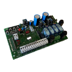
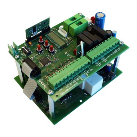
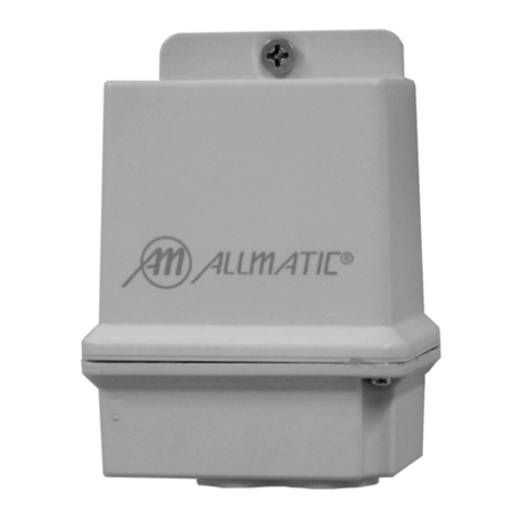
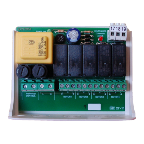
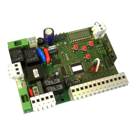
  9. Allmatic B1VR PROX User manual

Allmatic B1VR PROX User manual

ITA ENG FRA ESP DEU POR
1 / 4
6-1622293 rev2 04/05/2015
B1VR PROX
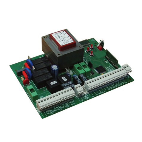
Control unit for 1 motor with anemometer input
1. Introduction
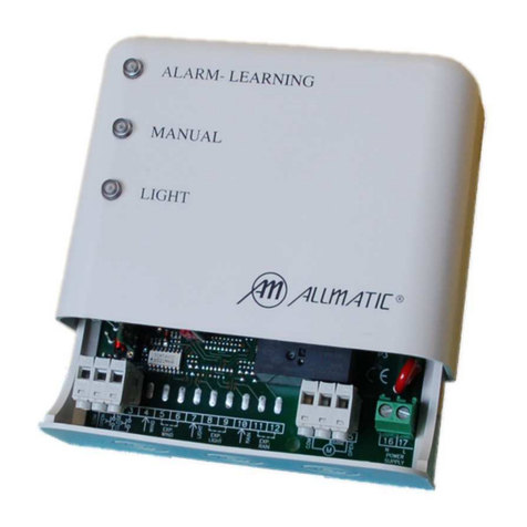
The control units of the series B1VR PROX are devices suitable to carry out the activation and the control of awnings and shutters in a simple and
complete way, designed to meet any requirement. This product can control a 230Vac motors up to 500W (max) of power. The B1VR PROX control
units, if equipped with the radio receiver module, use the innovative system of rolling code decoding, easy and intuitive on the installation. In the
extractable memory it is possible to memorize up to 1000 channel (8000 with optional memory) of the series Birol® and CLARUS. Includes an input for
a wind sensor (WIN Allmatic series), which allows to close the automation in case of danger situation, due to an excessive velocity of the wind. There
are also 2 separate inputs for the opening and the closing buttons and for programmed opening (“clock function” see section 7). In case where the
radio receiver is not installed, the presence of the buttons is necessary to control the automation.
WARNING: DO NOT INSTALL THE CONTROL UNIT WITHOUT READING THE INSTRUCTIONS BEFORE!!
2. Description
3. Electrical connections
Installation and advices
•
Connect the motor to the terminal boards 8,9,10 respecting
the scheme and the polarity of the motor (open =unrolling
awning, close= rolling up awning).
•
Connect the buttons open and close of the motor to the
terminal boards 5,6,7 respecting the scheme and trying to
separate as much as possible these cables from those
of the line tension and of the motor.
•
Connect the clock for motor to terminal boards 5 and 6 (refer
to the sections 7).
•
Connect the wind sensor to the terminal boards 4 and 5.
Also in this case, avoid to make the cable slide near to
to the cables of the line tension and of the motor, in
order to insulate it from external interferences. For a
connection scheme of an anemometer with more control
units, refer to the section 9.
•
Connect the cables of the line tension 230Vac to the terminal
boards 11, 12.
Preliminary checks
Move manually the automation in the middle of stroke, set the
wind trimmer about at minimum and move manually the
anemometer, be sure that the automation closes when the wind
allarm appear. If the automation opens check the connections of
the motor.
Connections wind sensor
Dip switch for the
selection of the functions Led of diagnosis of
the radio disturb
Jumper for wind
sensor expansion
Adjustment threshold
of wind alarm velocity
Radio receiver module
Learning/alarm led
Learning
button
Inputs fuse
F 50 mA
Line fuse
F 6.3 A
Transmitters
memory
WIN S:
Connect cables on inputs N°4 and
N°5 of the terminal board B1VR.
KAIROS S:
Connect cables on inputs N°4 and
N°5 of the terminal board B1VR.
NOTE: connection cables have no polarity.
NOTE: the control unit is also compatible with WIN EX sensor.
ITA ENG FRA ESP DEU POR
2 / 4
6-1622293 rev2 04/05/2015
4. Functions selectable by dip – switch
The control unit can work in different ways, according to how the dip – switches of selection are set.
4.1. Dip 1 OFF
•
Open and close button transmitters: with the use of a memorized transmitter Birol with 2 or 4 buttons and CLARUS,
pressing the key open, the awning opens completely, a second pressure of the key does not stop the awning. If you
want to stop the movement you must press the key related to the opposite movement, in this case the key close or
the key STOP for the CLARUS series. You must press again the key close in order to close. The same is for the
other key.
•
Open and close keys/switches at dead man: the automation is activated only during the closing of the contact,
releasing the key the automation stops itself.
•
If switches/deviators with fixposition are used and leaved on open or close, the automation will be completely open
or close, independently from the commands given by the transmitter.
4.2. Dip 1 ON ( NOT USED WITH FIX POSITION SWITCHES)
•
Transmitters with a step by step key: with the use of a memorized transmitter, pressing more times the key “a”or
“a1” you will obtain in sequence the function open – stop – close – stop – open……
•
Open and close buttons: pressing for a short instant the opening key, you will obtain the complete opening of the
automation until the end of the working time (fix as 7 minutes). In the same way, pressing for a short instant the
closing key, you will obtain the complete closing of the automation until the end of the working time.
•
If you keep pressed the open or close button for a short instant during the movement phase, you will stop the
automation.
4.3. Dip 2 OFF
•
In this modality of functioning, after a wind alarm, the control unit closes the automation. After 7 minutes the
automation can be opened only with a command given by transmitter, by key, or by a switch with fix position on
open. If a wind alarm arrives unexpectedly, the automation will be closed.
4.4. Dip 2 ON
•
In this modality of functioning, after a wind alarm, the control unit closes the automation and at the end of the alarm
time (7 minutes) opens it again, in the starting position only if the awning was stopped. Instead, if the automation
was in movement, the control unit will totally re– open if the automation was in opening phase or will remain closed
if the awning was in closing phase at the moment of the alarm.
•
If switches/deviators with fixposition are used and left on open, when the alarmtime exipires the automation will be
completely re-opened. You will obtain the same result by giving the command by transmitter or pressing the key
open once expired the alarm time
On
Off
Figura 2a: posizione a
On
Off
Figura 2b: posizione b
On
Off
Figura 2c: posizione c
On
Off
Figura 2d: posizione d
5. Wind alarm function
The control unit is equipped with an input for the reading of the velocity of the wind through anemometer. This function is helpful in order to avoid that
the automation can be damaged by a strong gust of wind: in this case the control unit enters in wind alarm and closes the automation.
•
During the phase of alarm, the led M1 signals the alarm by flashing. The alarm phase will lasts for about 7 minutes.
•
When alarm time is expired, if the wind is dropped under the alarm threshold, the automation will reopen in the same position than before the
alarm (function of automatic reopening). If the wind persists, the awning remains on closed position until the alarmstops.
•
If any fix position switch left on open is installed, when 7 minutes expire the automation will be completely reopened, instead if they are
positioned on close the automation won’t be reopened.
•
It is possible to adjust the intervention threshold of the wind alarmacting on the regulation trimmer, keeping in mind that by turning in clock –
wise sense it is possible to reach an higher threshold, so it will be necessary a stronger wind to make the control unit enter on alarm.
•
During the installation it is possible to cancel the waiting time of 7 minutes; to do this, press LEARN key few seconds after the dropping down
of the wind.
Important : in case of black out at first wind alarm the automation is reclosed and it does not open.
⇒
The functioning of the control unit after a wind alarm depends on the DIP 2 setting.
⇒
The intervention of the alarm has the control on all the other controls (transmitters, buttons).
NOTE: in case that the control unit is on the closing position and, through a manual moving, the automation is brought to the opening position, an
intervention of the sensor will not command a closing of the automation, bacause the control unit is still under the closing position.
ITA ENG FRA ESP DEU POR
3 / 4
6-1622293 rev2 04/05/2015
1. Opening of the memory: to open the memory fromtransmitter, make reference to the instructions of the transmitter in possession. Once opened
the memory of the control unit, this one signals it turning on the red led M1.
2. Press the key “a” or “a1” of the transmitter. The control unit automatically memorizes also the “b” or “b1” or “c” for the series CLARUS (“a” or “a1”
like “open” key , “b” or “b1” like “close” key and “c” like “stop” key. The control unit signals the memorization of the channel with two flashings if
the channel was not memorized, with one if the channel was already learned.
3. Once memorized the channel, the control unit goes back to the normal modality of functioning.
If no signal is transmitted by 20 seconds, the control unit automatically exits from the learning modality.
The control unit B1VR PROX (if radio receiver module is installed) can be controlled by all the Allmatic transmitters of the B.RO 433 MHz series
and by the CLARUS series. On the control unit there is the learning button (LEARN) with which it is possible to select where to memorize the
transmitter.
6. Apprendimento di un trasmettitore
1. Press and release the learning key (LEARN) present on the card, led M1 turns on.
2. Press the key “a” or “a1” of the transmitter. The control unit automatically memorizes also
the “b” or “b1” and the “c” key for the CLARUS series (“a” or “a1” like “open” key, “b” or “b1”
like “close” key and “c” like “stop” key). The control unit signals the memorization of the
channel with two flashings if the channel was not memorized, with one if the channel was
already learned.
3. Once memorized the channel, the control unit goes back to normal modality of functioning.
If no signal is transmitted by 20 seconds, the control unit automatically exits from the
learning modality.
a
b
c
a b
a
1
b
1
6.1 Transmitter learning with learning key
DIRECT MODE
(Activation with
3 blinkings)
“a”or “a1” open
“b”or “b1” close
“c”
(onlyCLARUS) stop
INVERSE MODE
(Activation with
2 blinkings)
“a”or “a1” close
“b”or “b1” open
“c”
(onlyCLARUS) stop
6.4 Erasing of a transmitter from the memory of a control unit
ERASING transmitter series B.ro:
) Press the hidden key “e” present on the transmitter; the red led M turns on. This operation is equivalent
to press the LEARNkey, but without access to the control unit.
2) Press at the same time for some seconds the hidden key and “a” key of the radio transmitter to erase (“e”
+ “a”). The control unit signals the happened erasing with 4 long blinks. After that the control unit goes back
to the normal modality of functioning.
This procedure will erase completely the transmitter from the control unit.
ERASING transmitter series CLARUS:
To erase one channel or the whole transmitter it is necessary to access to the internal menu of the transmitter.
To do this refer to the instructions of the transmitter in possession.
Warning: do not use this procedure in presence of more control units in function, because the opening of the memory would
happen for all the devices in which the channel is memorized. In this case cut off tension to the control units not interested.
PRESS the hidden
key “e”
PRESS at the same
time the hidden key
“e” + the “a” key
e
a b
a
1
b
1
e
a b
a
1
b
1
It is possible to reset the factory setting at every moment resetting the control unit. This operation erases also all the transmitters.
This operation must always be carried out with closed automation. To reset of the control unit:
1. Cut off the power supply to the control unit
2. Keep pressed the learning key
3. Give power supply to the card, always keeping pressed the self – learning key. After about 5 seconds, the led M1 starts to blink.
4. Release the learning key
5. At the switching off of the led, all the transmitters are erased and the default setting restored
6.5 Total erasing of the memory and reset of the factory setting
6.2 Learning of the successive transmitters with a transmitter already learnt
This option lets you to invert the functions of the buttons of the transmitters of B.RO. or CLARUS series: you canchange
from direct mode ( “a” or “a1”=>movement open, “b” or “b1”=>movement close, c=>stop only for CLARUS)
To inverse mode ( “a” or “a1”=>movement close, “b” or “b1”=>movement open, c=>stop only for CLARUS)
As default the control unit is set under direct mode. To change into the inverse mode, with powered control unit and still motor it will be enough:
1. Press and keep pressed the LEARNbutton
2. Keeping pressed the LEARN button change the state of the Dip.1
3. The control unit will execute 2 blinkings
4. Release the LEARN button and put back the Dip.1 in the desired position.
In order to come back to the direct mode repeat the procedure: this time the control unit will execute 3 blinkings.
NOTE: inverse mode has no effect on wired buttons.
The modification has effect on ALL the memorized transmitters, and on the transmitters that will be memorized on the control unit.
Reset the unit back to the direct mode.
6.3. Buttons inversion.
Pay attention to the inversion state of the buttons (see paragraph 6.3)
ITA ENG FRA ESP DEU POR
4 / 4
6-1622293 rev2 04/05/2015
8. Limit switch and working time adjusting
The position of limit switch in opening of the automation is settable by the limit switches of the used motors. However the control unit is provided with a
maximum working time of 7 minutes, to allow the automatic stop of the motor also in case of failure of the limit switches of the motor.
7. Clock function
The clock function cannot be used with the dead man modality
(DIP 1 OFF)
The clock function is used in those situations where you want to open and close the automation at specific times.
An external timer is necessary with a dry contact which remains closed for all the time where the automation must remain open, and must open the
contact when the automation must close. The contact must be connected to the input “open”, after 4 minutes of closed contact the control unit enters
the “Clock function”. The wall buttons can be normally used if the “Clock” function is not active, on the contrary any command, also by transmitter is
ignored. As usual, a wind alarm closes the automation which will completely reopens itself as soon as this is finished, independently from the position
of the dips of automatic reopening (dip 2).
9. Expansion of the wind sensor
Setting of the jumper for expansion wind sensor
CT= CONTROL UNIT
With a wind sensor used with one control
unit, leave the expansion jumper of the wind
sensor closed.
With a wind sensor used with THREE control units, leave
closed the expansion jumper of the wind sensor of the first
control unit and remove the one present in the second and
in the third control unit.
With a wind sensor used with SIX control units, leave closed
the expansion jumper of the wind sensor of the first control
unit and remove the one present in the second and in the
third, fourth, fifth and sixth control unit.
Technical specifications B1VR PROX
Power voltage 230 Vac +10% -15%
Motor output 230Vac 500W MAX cosΦ> 0.8
Card absorption 3W MAX (excluding accessories and utilities)
Motor operation time 7 minutes
Standby time after wind alarm 7 minutes
Operating temperature -10°C ... +60°C
Frequency (*) 433.92 MHz Super-reactive band 433.92 MHzSuper-reactive band 40.665 MHz Quartzed
Radio range in open field (*) 20 – 40m
Type of antenna (*) Incorporated stylus
Memorisable channels (*) 1000 with B.RO 1000 memory module (VARIABLE CODE)
Number of available codes (*) 18 billion billion (reception BIROL® VARIABLE CODE AND CLARUS)
30 – 60m 30 – 60m
(*) technical features valid only in presence of a radio receiver
CT1 CT1 CT2 CT3
CT1 CT2 CT3 CT4 CT5 CT6
JUMPER CLOSED JUMPER OPEN JUMPER OPEN JUMPER OPEN
GUARANTEE - In compliance with legislation, the manufacturer’s guarantee is valid from the date stamped on the product and is restricted to the re-
pair or free replacement of the parts accepted by the manufacturer as being defective due to poor quality materials or manufacturing defects. The
guarantee does not cover damage or defects caused by external agents, faulty maintenance, overloading, natural wear and tear, choice of incorrect
product, assembly errors, or any other cause not imputable to the manufacturer. Products that have been misused will not be guaranteed or repaired.
Printed specifications are only indicative. The manufacturer does not accept any responsibility for range reductions or malfunctions caused by environ-
mental interference. The manufacturer’s responsibility for damage caused to persons resulting from accidents of any nature caused by our defective
products, are only those responsibilities that come under Italian law.

Other Allmatic Control Unit manuals

Allmatic AV4 Guide

Allmatic

Allmatic AV4 Guide

Allmatic AS24 Safety guide

Allmatic

Allmatic AS24 Safety guide

Allmatic ACTION Guide

Allmatic

Allmatic ACTION Guide

Allmatic M2E User manual

Allmatic

Allmatic M2E User manual

Allmatic ACTION Guide

Allmatic

Allmatic ACTION Guide

Allmatic HELIOS KAIROS User manual

Allmatic

Allmatic HELIOS KAIROS User manual

Allmatic Clamp assist User manual

Allmatic

Allmatic Clamp assist User manual

Allmatic ACTION Guide

Allmatic

Allmatic ACTION Guide

Allmatic SCOR.AS User manual

Allmatic

Allmatic SCOR.AS User manual

Allmatic BIOS2 Safety guide

Allmatic

Allmatic BIOS2 Safety guide

Allmatic BIOS2 24V User manual

Allmatic

Allmatic BIOS2 24V User manual

Allmatic BIOS1 24V User manual

Allmatic

Allmatic BIOS1 24V User manual

Allmatic BIOS2 ECO Safety guide

Allmatic

Allmatic BIOS2 ECO Safety guide

Allmatic BIOS2 ECO Safety guide

Allmatic

Allmatic BIOS2 ECO Safety guide

Allmatic BIOS1 BRT Safety guide

Allmatic

Allmatic BIOS1 BRT Safety guide

Allmatic CT ACTION 09 Parts list manual

Allmatic

Allmatic CT ACTION 09 Parts list manual

Allmatic AS24 User manual

Allmatic

Allmatic AS24 User manual

Allmatic BIOS1 24V User manual

Allmatic

Allmatic BIOS1 24V User manual

Allmatic CT ACTION 09 Parts list manual

Allmatic

Allmatic CT ACTION 09 Parts list manual

Allmatic BAX900L User manual

Allmatic

Allmatic BAX900L User manual

Allmatic HELIOS KAIROS User manual

Allmatic

Allmatic HELIOS KAIROS User manual

Allmatic BIOS2 Safety guide

Allmatic

Allmatic BIOS2 Safety guide

Allmatic B1EE ERMES2 Safety guide

Allmatic

Allmatic B1EE ERMES2 Safety guide

Allmatic BIOS1 24V User manual

Allmatic

Allmatic BIOS1 24V User manual

Popular Control Unit manuals by other brands

DEMA 466P installation instructions

DEMA

DEMA 466P installation instructions

Bosch Rexroth MKK 12-40 instructions

Bosch

Bosch Rexroth MKK 12-40 instructions

Aqara Hub E1 user manual

Aqara

Aqara Hub E1 user manual

Kohler DTV+ Installation and care guide

Kohler

Kohler DTV+ Installation and care guide

Enerpac VE32 Repair Parts Sheet

Enerpac

Enerpac VE32 Repair Parts Sheet

VIA Technologies 40 quick start guide

VIA Technologies

VIA Technologies 40 quick start guide

claber Evolution 90821 user manual

claber

claber Evolution 90821 user manual

TA UDV installation instructions

TA

TA UDV installation instructions

Adeunis RF ARF8133A user guide

Adeunis RF

Adeunis RF ARF8133A user guide

infiniDome GPSdome 1.01 installation manual

infiniDome

infiniDome GPSdome 1.01 installation manual

Simply Automated UMI manual

Simply Automated

Simply Automated UMI manual

Sonder Allegro 576 Series Technical Installation & Operation Manual

Sonder

Sonder Allegro 576 Series Technical Installation & Operation Manual

Infineon ASCLIN SPI Master 1 manual

Infineon

Infineon ASCLIN SPI Master 1 manual

TimeTec BLE-2 installation guide

TimeTec

TimeTec BLE-2 installation guide

Fluidmaster PerforMAX 400H Quick install guide

Fluidmaster

Fluidmaster PerforMAX 400H Quick install guide

WAREMA MSE Compact 2 REG Operating and installation instructions

WAREMA

WAREMA MSE Compact 2 REG Operating and installation instructions

Siemens SIMATIC NET 6GK1110-1AA00 manual

Siemens

Siemens SIMATIC NET 6GK1110-1AA00 manual

Game ready 550550 user manual

Game ready

Game ready 550550 user manual

manuals.online logo
manuals.online logoBrands
  • About & Mission
  • Contact us
  • Privacy Policy
  • Terms and Conditions

Copyright 2025 Manuals.Online. All Rights Reserved.