Page 4
Distribution Module Wiring
Step 3
Card Wiring
• These instructions apply for connecting the Command Center to the Distribution Module as well as for
connecting Emergency Phones to the Distribution Module.
• The maximum cable run to the Distribution Module from the base station phone is 6,200’ for 22AWG and
3,900’ for 24AWG cable.
• The maximum cable run to an Emergency Phone is 112,500’ for 22AWG and 70,300’ for 24AWG cable.
• When connecting Emergency Phones to the Distribution Module, EIA/TIA Standards MUST be followed for
wiring the locations to single pair 22AWG or 24AWG UTP twisted, shielded cable.
Note: When using the Command Center for non-elevator applications, it is recommended to use a biscuit
jack for connecting each phone. The communication wire pair should be connected to the red and green
screw terminals on the biscuit jack. This will prevent loose connections that can cause the system to
malfunction.
Option 1
12-36 Zone System:
• On top of each port there is a label indicating connection:
SLT is the port used for connecting emergency phones
DKP is the port used for connecting Command Center phone(s)
TWT is the port used for outside Telco line
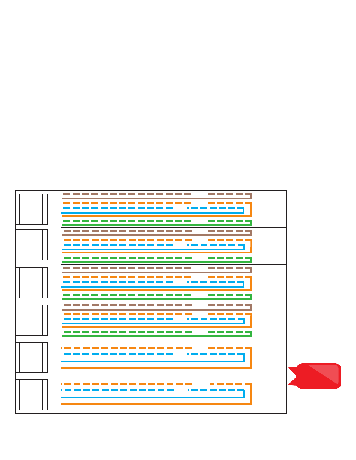
• Plug the supplied RJ45 pigtail cables into the ports following the wiring chart and pin-out color scheme
below
• Refer to the top of the cards to see what type of port and number of extensions
• The same pin-out color scheme should be used for the primary card and for all additional cards. The
system uses T568-A for pin-out wiring.
• The rst card installed will always be:
• Port 1: (01-04) Connection for 4 Emergency Phones (SLT)
• Port 2: (05-06) Connection for 2 Telco Lines (TWT)
• Port 3: (07-08) Connection for up to 2 Command Center Phones (DKP)