manuals.online logo
Brands
  1. Home
  2. •
  3. Brands
  4. •
  5. Alpine
  6. •
  7. Computer Hardware
  8. •
  9. Alpine PXA-H600 User manual

Alpine PXA-H600 User manual

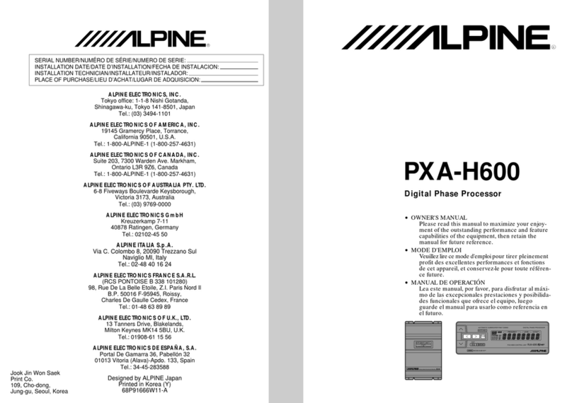
Digital Phase Processor
PXA-H600
English
ßGUIDE FOR INSTALLATION AND CONNECTIONS
≠Please read this GUIDE FOR INSTALLATION AND CONNECTIONS and the OWNER'S
MANUAL thoroughly to familiarize yourself with each control and function. We at ALPINE
hope that your new PXA-H600 will give you many years of listening enjoyment.
In case of problems when installing your unit, please contact your authorized ALPINE
dealer.
Français
ßGUIDE D'INSTALLATION ET DE CONNEXIONS
≠Prière de lire attentivement ce GUIDE D' INSTALLATION ET DE CONNEXIONS et le MODE
D'EMPLOI pour se familiariser avec chaque commande et fonction. Chez Alpine, nous
espérons que le nouveau PXA-H600 donnera de nombreuses années de plaisir d'écoute.
En cas de problèmes lors de l'installation de l'unité, prière de contacter le revendeur agréé
d'ALPINE.
(RCS PONTOISE B 338 101 280)
Jook Jin Won Saek Print Co.
109, Cho-dong, Jung-gu,
Seoul, Korea
68P91666W12-A
Printed in Korea (Y)
Español
ßGUIA DE INSTALACION Y CONEXIONES
≠A fin de familiarizarse con los controles y funciones de la unidad, lea detenidamente esta
GUIA DE INSTALACION Y CONEXIONES junto con el MANUAL DE OPERACION. Nosotros
en ALPINE esperamos que su nuevo PXA-H600 le brinde muchos años de placer auditivo.
En caso de presentarse algún problema durante la instalación de Ia unidad, tome contacto
con su distribuidor autorizado ALPINE.
Puntos que debe respetar para un uso seguro
Points à respecter pour une utilisation sûre
Points to Observe for Safe Usage
≠Lea atentamente este manual antes de comenzar la operación y la utilización del sistema
sin riesgos. Declinamos toda responsabilidad si se ocasionan problemas por no respetar
las instrucciones dadas en este manual.
≠Este manual utiliza diversas ilustraciones para mostrar como utilizar este aparato de
manerasegura,paraevitarlaexposicióndesímismoydeotraspersonasapeligrosypara
evitar de estropear el aparato. He aquí la significación de dichas ilustraciones. Es muy
importante que las comprenda bien para la lectura de este manual.
≠Significación de las ilustraciones
≠Lire attentivement ce manuel avant de commencer l'opération et l'utilisation du système
en toute sécurité. Nous dégageons toute responsabilité des problèmes résultant du non-
respect des instructions décrites dans ce manuel.
≠Cemanuel utilise divers affichages illustrés pour montrer comment utilisercet appareil en
toute sécurité, pour éviter de s'exposer soi-même et les autres personnes aux dangers et
pouréviterd'endommagerl'appareil.Voicilasignificationdecesaffichagesillustrés.Ilest
important de bien les comprendre pour la lecture de ce manuel.
≠Signification des affichages
≠Readthismanualcarefullybeforestartingoperation and use thissystemsafely. We cannot
be responsible for problems resulting from failure to observe the instructions in this
manual.
≠This manual uses various pictorial displays to show how to use this product safely and to
avoidharmtoyourselfandothers anddamagetoyourproperty.Hereiswhat thesepictorial
displays mean. Understanding them is important for reading this manual.
≠Meaning of displays
Warning
Thislabelisintendedtoalerttheusertothepresenceofimportantoperating
instructions.
Failure to heed the instructions can result in injury or material damage.
Cette étiquette a pour but de prévenir l'utilisateur de la présence
d'instructions importantes.
Sicesinstructionsnesontpas suivies,desblessures gravesoumortelles
risquent d'être occasionnées.
Avis
Esta etiqueta previene al usuario de la presencia de instrucciones
de operación importantes.
Sinosigue estasinstrucciones,correelriesgodeocasionarheridas
graves o mortales.
Advertencia
Esta etiqueta previene al usuario de Ia presencia de instrucciones
de operación importantes.
Sinosigueestas instrucciones,correelriesgodeocasionarheridas
o pérdidas materiales.
Cette étiquette a pour but de prévenir l'utilisateur de la présence d'ins-
tructions importantes.
Sices instructions ne sont pas suivies, des blessures ou des dommages
matériels risquent d'être occasionnés.
Attention Prudencia
This label is intended to alert the user to the presence of important
operating instructions.
Failure to heed the instructions will result in severe injury or death.
Caution
Warning
DO NOT DISASSEMBLE OR ALTER
Attempts to disassemble or alter may lead to accident, fire or electric shock.
KEEP SMALL ARTICLES OUT OF THE REACH OF CHILDREN
Store small articles (batteries, screws, etc.) in places not accessible to children. If swallowed, consult
a physician immediately.
USE THE CORRECT AMPERE RATING WHEN REPLACING FUSES
Replace fuses only with fuses of the same rated ampere. Failure to do so may result in fire etc.
USE ONLY IN VEHICLES WITH A 12 VOLT NEGATIVE GROUND
Use only in vehicles with a 12 volts negative (–) ground. (Check with your dealer if you are not sure.)
Failure to do so may result in fire etc.
BEFORE WIRING, DISCONNECT THE CABLE FROM THE NEGATIVE BATTERY TERMINAL
Before doing any electrical wiring, disconnect the cable from the negative (–) terminal of the battery.
Failure to do so may result in electric shock or injury due to electrical shorts.
KEEP ELECTRICAL CABLES TOGETHER TO AVOID OPERATING HAZARDS
Arrange wiring and cables in compliance with the installation manual to prevent obstructions when
driving. Cables or wiring that obstructs or hangs up on places such as the steering wheel, gear lever,
brake pedals can be extremely hazardous.
DO NOT CUT AWAY THE WIRE SHEATH AND USE POWER TO OTHER EQUIPMENT
Never cut away the cable shielding to use power to another piece of equipment. Doing so will exceed the
current carrying capacity of the wire and result in fire or electric shock.
DO NOT INSTALL IN LOCATIONS WHICH MIGHT HINDER VEHICLE OPERATION
Do not install in locations which might create hazards for the vehicle occupants or hinder vehicle
operation (such as the steering wheel or gear shift) by obstructing forward vision or hampering move-
ment etc.
DO NOT DAMAGE PIPE OR WIRING WHEN DRILLING HOLES
When drilling holes in the chassis for installation, take precautions so as not to contact, damage or
obstruct pipes, tanks or electrical wiring. Failure to take such precautions may result in fire.
DO NOT USE NUTS OR BOLTS IN THE BRAKE SYSTEM WHEN MAKING INSTALLATION OR GROUND
CONNECTIONS
Neveruse safety-relatedparts suchasboltsornuts inthe steeringorbrake systemsor tankstomake wiring
installationsor ground connections.Using such partscoulddisable control ofthevehicle andcausefire etc.
Avis
NE PAS DÉMONTER NI MODIFIER
Toute tentative de démontage ou modification peut provoquer un accident, un incendie ou un choc
électrique.
NE PAS LAISSER DE PETITES PIÈCES À PORTÉE DES ENFANTS
Rangez les petites pièces (piles, vis, etc.) hors de portée des enfants. En cas d’ingestion, faites
immédiatement appel à un médecin.
REMPLACEZ LES FUSIBLES PAR DES FUSIBLES DE CAPACITÉ APPROPRIÉE
Afind’évitertoutrisqued’incendieou autreproblème,remplacezlesfusiblesseulementpardes fusibles
ayant le même nombre d’ampères.
UTILISEZ CET APPAREIL UNIQUEMENT DANS LES VOITURES À CIRCUIT ÉLECTRIQUE DE 12 VOLTS ET
MASSE NÉGATIVE
Cet appareil ne doit être installé que dans les voitures à circuit de 12 volts et masse négative (–). (En
cas d’incertitude à ce sujet, demandez conseil à votre revendeur.) Sinon, il y a risque d’incendie, etc.
AVANT TOUTE CONNEXION, DÉBRANCHEZ LE CÂBLE DE LA BORNE NÉGATIVE DE LA BATTERIE
Avant d’entreprendre toute connexion électrique, débranchez le câble de la borne négative (–) de la
batterie. Vous risquez sinon un choc électrique ou des blessures causées par un court-circuit.
REGROUPEZ LES CÂBLES POUR NE PAS ÊTRE GÊNÉ
Disposez les câbles correctement et regroupez-les en vous conformant aux instructions du mode
d’emploi pour ne pas être gêné pendant la conduite. Des câbles ou fils obstruant ou pendant près du
volant,dulevierdechangementde vitesse,delapédaledefrein,entreautre, peuventêtreextrêmement
dangereux.
NE PAS ENLEVER LA GAINE D’UN FIL POUR ALIMENTER UN AUTRE APPAREIL
Ne pas enlever la gaine d’un fil pour alimenter un autre appareil, car la capacité du fil risque d’être
insuffisante, ce qui peut provoquer un incendie ou un choc électrique.
NE PAS INSTALLER DANS DES ENDROITS POUVANT GÊNER LA CONDUITE DU VÉHICULE
Ne pas installer l’appareil dans un endroit où il risque de blesser un passager ou de gêner la conduite
(parexemple, près du volant ou du levier de changement de vitesse), d’obstruerla vue ou de gêner les
mouvements du conducteur.
NE PAS ENDOMMAGER LES TUYAUX NI LES FILS QUAND VOUS PERCEZ DES TROUS
Quandvouspercezdestrousdanslechâssispour installer l’appareil, veillez à ne pas toucher, endom-
mager ou obstruer les tuyaux, réservoir ou fils électriques. L’absence de telles précautions peut pro-
voquer un incendie.
NE PAS UTILISER LES ÉCROUS NI LES BOULONS DU SYSTÈME DE FREINAGE LORS DE L’INSTALLATION
OU LA MISE À LA MASSE
Ne jamais utiliser des éléments importants pour la sécurité, tels les boulons ou écrous de la direction,
du système de freinage ou du réservoir pour la fixation des des fils ou la mise à la masse. L’utilisation
de telles pièces pourrait causer une perte de contrôle du véhicule ou provoquer un incendie.
Attention
FAITES INSTALLER L’APPAREIL ET POSER LES FILS PAR UN PROFESSIONNEL
La pose des fils et l’installation de l’appareil exigent des connaissances techniques spéciales et une
certaine expérience. Pour des raisons de sécurité, contactez le revendeur chez qui vous avez acheté
cet appareil pour qu’il vous l’installe.
NE PAS BLOQUER LES ORIFICES DE VENTILATION NI LES DIFFUSEURS DE CHALEUR
Ne pas bloquer les orifices de ventilation ni les diffuseurs de chaleur, sinon une surchauffe interne
risque de se produire et de provoquer un incendie.
UTILISEZ LES ACCESSOIRES SPÉCIFIÉS ET FIXEZ-LES CONVENABLEMENT
Veillezà n’utiliserque les accessoiresspécifiés. L’utilisationdetoute autrepièce risque d’endommager
les circuits internes de l’appareil et de ne pas garantir une installation assez résistante. L’appareil
pourrait se détacher et créer un risque d’accident.
NE PAS INSTALLER DANS UN ENDROIT EXPOSÉ À UNE HUMIDITÉ ET UNE POUSSIÈRE INTENSES
Evitez d’installer l’appareil dans un endroit exposé à une grande quantité d’humidité et de poussière.
L’humidité et la poussière peuvent pénétrer dans l’appareil et causer un dégagement de fumée ou un
incendie.
EFFECTUEZ CORRECTEMENT LES CONNEXIONS
Des connexions inappropriées peuvent causer un incendie ou un accident.
DISPOSEZ LES FILS DE SORTE QU’ILS NE SOIENT PAS COINCÉS
Disposez les fils et les câbles de sorte qu’ils ne risquent pas d’être coincés par des pièces mobiles,
comme les rails de siège, et ne pas les mettre au contact d’angles aigus ou pointus, car ils pourraient
être endommagés.
Advertencia
NO DESMONTE NI ALTERE
Si intenta desmontar o alterar el aparato podrá ocasionar un accidente, incendio o descarga eléctrica.
MANTENGA LOS OBJETOS PEQUEÑOS FUERA DEL ALCANCE DE LOS NIÑOS
Guarde los objetos pequeños (pilas, tornillos, etc.) en lugares donde los niños no puedan acceder a
ellos. Si tragasen algo, consulte a un médico inmediatamente.
UTILICE EL AMPERAJE CORRECTO CUANDO REEMPLACE FUSIBLES
Reemplace los fusibles solamente por otros del mismo amperaje. De no hacerlo así podrá ocasionar
un incendio, etc.
UTILICE EL APARATO SOLAMENTE EN VEHICULOS DE 12 VOLTIOS CON NEGATIVO A MASA
Utilícelo solamente en vehículos de 12 voltios con negativo (–) a masa. (Consulte a su distribuidor si
tiene dudas.) De no hacerlo así podría ocasionar un incendio, etc.
ANTES DE HACER EL CABLEADO, DESCONECTE EL CABLE DEL BORNE NEGATIVO DE LA BATERIA
Antes de hacer cualquier cableado eléctrico, desconecte el cable del borne negativo (–) de la batería.
Deno hacerlo así podrá ocasionar una descarga eléctricao heridas debido a cortocircuitos eléctricos.
MANTENGA LOS CABLES ELECTRICOS JUNTOS PARA EVITAR PROBLEMAS DE FUNCIONAMIENTO
Coloqueelcableadoyloscablesdeacuerdoconlas explicacionesdelmanual deinstalaciónparaevitar
obstruccionescuandoconduzca.Loscablesocableadoquepuedanobstruyanoquedencolgandode
lugarestales como el volante, palancadecambios o pedal de frenospuedenresultarextremadamente
peligrosos.
NO CORTE EL RECUBRIMIENTO DEL CABLE PARA COGER CORRIENTE PARA OTROS APARATOS
Nocorte nuncaelrecubrimiento de cablepara coger corrienteparaotros aparatos.Silo haceexcederá
la capacidad de conducción de corriente del cable y ocasionará incendios o descargas eléctricas.
NO INSTALE EL APARATO DONDE PUEDA DIFICULTAR LA OPERACION DEL VEHICULO
No instale el aparato en lugares que pueda crear riesgos a los ocupantes del vehículo o dificultar la
operación del mismo (tales como el volante o palanca de cambios) obstruyendo la visibilidad al frente
o restringiendo sus movimientos, etc.
NO DAÑE LOS TUBOS O CABLEADO CUANDO TALADRE AGUJEROS
Cuando taladre agujeros en el chasis para instalar el aparato, tome las debidas precauciones para no
tocar, dañar u obstruir los tubos, depósitos o cableado eléctrico. Si no toma estas precauciones podrá
ocasionar un incendio.
NO UTILICE TUERCAS NI PERNOS EN EL SISTEMA DE FRENOS CUANDO HAGA LA INSTALACION O
CONEXIONES A MASA
No utilice nunca partes relacionadas con la seguridad, tales como pernos y tornillos de la dirección,
sistema de frenos o depósitos para hacer la instalación del cableado o conexiones a masa. El uso de
estas partes con estos fines podrá inutilizar el control del vehículo y causar un incendio, etc.
Precautions Précautions Precauciones
IMPORTANT
Please record the serial number of your unit in the space provided on the back cover of
Owner‘s Manual and keep it as a permanent record. The serial number plate is located on
the bottom of the unit.
IMPORTANT
Enregistrer le numéro de série de l'appareil dans l'espace prévu au dos du mode d'emploi
et le conserver en permanence. La plaque de numéro de série est située au fond de
l'appareil.
IMPORTANTE
Anote el número de serie de su unidad en el espacio proporcionado en la cubierta
posterior del manual de operación, y consérvelo como un registro permanente. La placa
con el número de serie está ubicada en la parte inferior de la unidad.
Wiring Connections
Improper wiring connections could cause serious damage to your audio system. Be sure you:
1. DO NOT connect (–) wires from left and right speakers together.
2. DO NOT ground any speaker wires.
3. DO NOT run wires where they may be pinched or cut.
4. DO NOT leave bare speaker terminals exposed. They may contact the vehicle chassis and
cause a short.
Fuse
When replacing the fuse(s), the replacement fuse must be of the same amperage as shown on
thefuseholder. If the fuse(s) blows more than once, carefully check all electricalconnectionsfor
shorted circuitry. Also have your vehicle’s voltage regulator checked. Do not attempt to repair
the unit yourself : return it to your Alpine dealer or nearest Alpine Service Station for servicing.
Temperature
Inorderto ensure proper performance, be sure the temperatureinyourvehicle is above 14˚F
(–10˚C) and below 140˚F (60˚C) before turning your unit on. Good air circulation is essential
to prevent internal heat build-up in the unit.
Câblage
Des connexions incorrectes peuvent endommager sérieusement la chaîne audio. S’assurer de:
1. NE PAS connecter les câbles (–) des haut-parleurs gauche et droit ensemble.
2. NE PAS mettre à la masse les câbles de haut-parleur.
3. NE PAS placer les câbles à un endroit où ils peuvent être coincés ou coupés.
4. NE PAS laisser exposer des bornes de haut-parleurs dénudées. Elles peuvent entrer en
contact avec le châssis de la voiture et provoquer un court-circuit.
Fusible
Lors du remplacement du (des) fusible (s), le (s) fusible (s) de remplacement doit (doivent) être
demême ampérage qu’indiqué sur le porte-fusible. Si le(s)fusible(s) saute (sautent) plus d’une
fois, vérifier correctement toutes les connexions électriques pour rechercher un court-circuit.
Vérifier également le régulateur de tension de la voiture. Ne pas essayer de réparer soi-même
l’appareil; le retourner au revendeur Alpine ou au centre de dépannage Alpine le plus proche.
Température
Afin de garantir une performance correcte, s’assurer que la température dans la voiture est
au-dessus de –10˚C et au-dessous de 60˚C avant de mettre l’appareil sous tension. Une bonne
ventilation d’air est essentielle pour éviter une accumulation de chaleur dans l’appareil.
Conexiones
Laconexiónincorrectadelos cablespodrá causarserios dañosa susistemadeaudio.Asegúrese
de:
1. NO conectar conjuntamente los cables (–) de los altavoces izquierdos y derechos.
2. NO conectar a tierra ninguno de los cables de altavoces.
3. NO tender los cables en lugares donde puedan pellizcarse o cortarse.
4. NO dejar los terminales de los altavoces expuestos. Estos podrían hacer contacto con el
chasis del automóvil y causar un cortocírcuito.
Fusible
Al reemplazar un fusible, asegúrese de que el (los) fusible (s) nuevo (s) sea (n) del amperaje
indicado en el portafusible. Si el (los) fusible (s) vuelve (n) a quemarse, revise cuidadosamente
todas las conexiones eléctricas y determine si se han producido cortocircuitos. Haga también
revisar el regulador de tensión de su automóvil. No intente reparar la unidad usted mismo;
llévela donde su distribuidor Alpine o a la estación de servicio Alpine más cercana.
Temperatura
Con el fin de garantizar el funcionamiento correcto de la unidad, asegúrese de que al encen-
der el equipo, la temperatura en el interior de su automóvil sea superior a –10˚C e inferior a
60˚C.Una buena circulación delairees esencial para evitarlaacumulación de calor enelinterior
de la unidad.
Caution
HAVE THE WIRING AND INSTALLATION DONE BY EXPERTS
Thewiringandinstallationofthisunitrequiresspecialtechnicalskillandexperience.Toensuresafety,
always contact the dealer where you purchased this unit to have the work done.
DO NOT BLOCK VENTS OR RADIATOR PANELS
Donot blockair vents orheat dischargeplates.Blocking themwill cause heatto buildupinside andmay
result in fire.
USE SPECIFIED ACCESSORY PARTS AND INSTALL THEM SECURELY
Besuretouse only the specified accessory parts. Use of other than designated parts may damage this
unit internally or may not securely install the unit in place as parts that come loose can create hazards.
DO NOT INSTALL IN LOCATIONS WITH HIGH MOISTURE OR DUST
Avoidinstalling the unit in locationswithhigh incidence of moistureordust.Moisture or dust thatpenetrates
into this unit may cause smoke or fire.
MAKE THE CORRECT CONNECTIONS
Failure to make the correct connections can cause fire or accident to occur.
ARRANGE THE WIRING SO IT IS NOT CRIMPED OR PINCHED
Route the cables and wiring so as not be crimped by moving parts like seat rail or make contact with
sharp or pointed spots which might damage the wiring.
Prudencia
ENCARGUE EL CABLEADO Y LA INSTALACION A UN EXPERTO
Elcableadoylainstalaciónde estaunidadprecisadeconocimientostécnicosespecialesy experiencia.
Para garantizar la seguridad, póngase siempre en contacto con el distribuidor al que haya comprado
esta unidad para que se la instale.
NO BLOQUEE LOS PANELES DE VENTILACION NI DEL RADIADOR
No bloquee los orificios de ventilación o placas de disipación del calor. Si los bloquea el aire se
acumulará en el interior y podrá ocasionar un incendio.
UTILICE LOS ACCESORIOS ESPECIFICADOS E INSTALELOS FIRMEMENTE
Asegúrese de utilizar solamente los accesorios especificados. La utilización de otros accesorios no
especificados podrá ocasionar daños internos a la unidad o que ésta no quede firmemente instalada
y las partes flojas creen situaciones peligrosas.
NO INSTALE EL APARATO EN UN LUGAR DE MUCHA HUMEDAD O POLVO
Eviteinstalar launidad en lugaresdonde hayamuchahumedad opolvo. La humedady elpolvopueden
introducirse en la unidad y ocasionar un cortocircuito o incendio.
HAGA LAS CONEXIONES CORRECTAMENTE
Si no hace las conexiones correctamente podrá ocasionar un incendio o accidente.
DISPONGA EL CABLEADO DE FORMA QUE NO SE CORTE O PELLIZQUE
Tiendaloscables yelcableadodeforma queno vayanasercortadospor laspartesmóviles,talescomo
el raíl del asiento, o tocar partes afiladas o puntiagudas que puedan dañarlos.
English
Mounting Microphone
Mounting Location
Mount the microphone on the rear-view mirror, headrest, sun
visor, or other appropriate location.
1. Peel off the protective papers from the adhesive side of the
Velcro fasteners. Attach 2 pieces of the Velcro fasteners on
to the microphone holder base and the other side of the
Velcro fastener on the spot where the microphone holder
base is located.
2. InsertthemicrophoneintotheY-shapedholderontheholder
base.
Français
Emplacement
Installerlemicrophonesurlerétroviseur,l’appuie-tête,lepare-
soleil ou tout autre endroit approprié.
1. Décoller la pellicule de protection de la face adhésive des
bandes Velcro. Coller deux bandes Velcro sous le porte-
microphone et les deux autres faces des bandes Velcro à
l’endroit où le porte-microphone doit être fixé.
2. IInsérer le microphone dans la partie en Y du porte-micro-
phone.
Español
Lugar para montar el micrófono
Monteelmicrófonoenelretrovisor,reposacabezas,quitasol,
u otro lugar apropiado.
1. Pele los papeles de protección de la parte adhesiva de las
cintas Velcro. Adhiera 2 trozos de cinta Velcro a la parte
inferior del soporte del micrófono y luego coloque el so-
porte del micrófono, con la otra cara adhesiva de la cinta
Velcro, en donde quiera poner el micrófono.
2. Inserte el micrófono en la parte en forma de Y del soporte
del micrófono.
Montaje del micrófono
Montage du microphone
Peel off.
Décaper.
Pelar.
Velcro Tape
Bande Velcro
Cinta Velcro
Microphone
Microphone
Micrófono
Microphone Holder
Porte-microphone
Soporte del micrófono
Français
Installation
Le PXA-H600 comprend deux composants:
l’unité de commande et l’unité de base.
• Sila bande Velcro est utilisée pour l’installa-
tion de l’unité de commande et de l’unité de
base,couperlabandeVelcro(laplusgrande)
en 2 morceaux.
aAttention:
Ne pas installer l’unité de commande près de
l’airbag du siège passager avant.
• Vérifier l’emplacement d’installation.
• Déterminerl’emplacementsur le tableau de
bord (au centre et à plat).
nstallation avec la bande Velcro
1. Sans séparer les deux morceaux de la ban-
deVelcro, enlever la pellicule de protection
d’uncôté etcollerla bandeau dosdel’unité
de commande.
2. S’assurerquel’endroitoùla bandedoit être
colléeest propre etsec. Décoller lapellicule
sur l’autre face de la bande Velcro.
3. Poserl’unitédecommande àl’endroit choi-
si et appuyer dessus pour bien la fixer.
Installation avec la pièce encastrable
1. Aprèsavoirdéterminél’emplacement,fixer
lapièceencastrableavecdesvis(M2.9x20).
2. Insérer l’unité de commande dans la pièce
encastrabledesorte qu’ellesoitbienbloquée.
Installation avec la pièce encastrable et le cadre
1. Pratiquer une ouverture de la dimension
extérieuredu cadre dans le tableaudebord
à l’endroit souhaité.
2. Insérer l’unité de commande dans la pièce
encastrable de sorte qu’elle soit bien blo-
quée.
3. Insérer l’unité de commande et la pièce
encastrable dans le cadre et les fixer.
4. Insérer l’unité de commande avec la pièce
encastrableetlecadredansl’ouverturepra-
tiquée à l’étape 1 et les fixer.
UNITE DE BASE
sMontage avec bande Velcro
Si la bande Velcro fournie n’a pas été utili-
sée pour fixer l’unité de commande, elle
peut être utilisée pour fixer l’unité de base.
dUtilisation des vis de montage (fournies)
L’unité de base peut être installée sous le
siège en utilisant les vis de montage.
English
Installation
ThePXA-H600 ismadeup oftwocomponents:
the Control Unit and Base Unit.
• If you use the Velcro fastner to install the
Control Unit and Base Unit, cut the Velcro
fastner (larger one) into 2 pieces.
aCAUTION:
Do not install the control unit near the air-bag
of the front passenger’s seat.
• Check the installing location.
• Determinetheinstallinglocationonthedash-
board (in the center, and flat position).
Installation using Velcro tape
1. Withoutseparatingthetwopiecesof Velcro
tape,peel off thepaperbacking on oneside
and place on the back of the control unit.
2. Makesure thelocationselected is freefrom
moisture or dirt. Peel off the backing paper
fromtheothersideoftheVelcrotapeonthe
control.
3. Placethecontrol unit on the installing loca-
tion and push the unit to fix securely.
Installation using flush mount
1. Afterdeterminingtheinstallinglocation,in-
stall the flush mount with screws (M2.9 x
20).
2. Insert the control unit into the flush mount
to lock securely.
Installation using flush mount and bracket
mount
1. Make a hole to match the external dimen-
sions of bracket mount on the installation
location of the dashboard.
2. Insert the control unit into the flush mount
to lock securely.
3. Insertthecontrolunitandflushmountcom-
bined into the bracket mount and fix them.
4. Insert the control unit, flush mount and
bracketmountcombinedintotheholemade
at step 1 and fix them.
BASE UNIT
sVelcro Fastener Mounting
If you didn’t use the Velcro fastener sup-
plied to mount the Control Unit, you can
use it to mount the Base Unit.
dUsing the Mounting Screws (Supplied)
The Base Unit can be mounted under the
seat using the mounting screws.
Español
Instalación
El PXA-H600 se compone de dos unidades: la
unidad de control y la unidad de base.
• Si utiliza la cinta Velcro para instalar la uni-
dad de control y la unidad de base, divida la
cinta Velcro (la más larga) en 2 trozos.
aPRECAUCION:
Noinstale launidadde controlcercadel airbag
del asiento del pasajero delantero.
• Inspeccione el lugar de instalación.
• Determineel lugardeinstalación eneltable-
rodeinstrumentos(enelcentro,yenposición
plana).
Instalación utilizando la cinta Velcro
1. Sin separar los dos trozos de cinta Velcro,
pele el papel de protección de una de las
carasde lacinta yadhiéralaa laparte poste-
rior de la unidad de control.
2. Asegúresedequeellugarelegidoestéexen-
to de humedad y suciedad. Pele el papel de
protección de la otra cara de la cinta Velcro
adherida a la unidad de control.
3. Coloque la unidad de control en el lugar
donde vaya a instalarla y haga presión so-
bre ella para que se adhiera firmemente.
Instalación utilizando la montura empotrada
1. Unavezhayadeterminadoel lugarde insta-
lación, instale la montura empotrada con
los tornillos (M2,9 x 20).
2. Inserte la unidad de control en la montura
empotrada para fijarla firmemente.
Instalación utilizando la montura empotrada
y el marco de montaje
1. Haga un agujero igual a las medidas exter-
nas del marco de montaje en el lugar del
tablerode instrumentos dondevayaa reali-
zar la instalación.
2. Inserte la unidad de control en la montura
empotrada para fijarla firmemente.
3. Inserte la unidad de control y la montura
empotrada conjuntamente en el marco de
montaje y fíjelos.
4. Inserte la unidad de control, montura empo-
tradaymarcodemontajeconjuntamenteenel
agujero que ha hecho en el paso 1 y fíjelos.
UNIDAD DE BASE
sMontaje con la cinta Velcro
Si no ha usado la cinta Velcro incluida
para montar la unidad de control, usted
podrá usarla para montar la unidad base.
dUsode los tornillosde montaje (provistos)
La unidad de base puede ser montada de-
bajo del asiento utilizando los tornillos de
montaje.
Velcro Tape
Bande Velcro
Cinta Velcro
Dashboard
Tableau de bord
Tabiero de instrumentos
Control Unit
Unité de commande
Unidad de control
Bracket Mount
Cadre
Marco de montaje
Bracket Mount
Cadre
Marco de montaje
Flush Mount
Pièce encastrable
Montura empotrada
Base Unit
Unité de base
Unidad de base
Peel off.
Décaper.
Pelar.
Velcro Tape(Larger one)
Bande Velcro
Cinta Velcro
Attach to the vehicle (such as under the dashboard).
Fixer à la voiture (par exemple, sous le tableau de bord).
Fijar al automóvil (por ejemplo,debajo del tablero de instrumentos).
Self-Tapping Screws (M4
~
14)
Vis autotaraudeuses (M4
~
14)
Tornillos autorroscantes (M4
~
14)
Base Unit
Unité de base
Unidad de base
12
3
Tapping Screws (M2.9
~
20)
Vis autotaraudeuses (M2.9
~
20)
Tornillos autorroscantes (M2.9
~
20)
Dashboard
Tableau de bord
Tabiero de instrumentos
Flush Mount
Pièce encastrable
Montura empotrada

Connexions
REMARQUE:
Lorsque le PXA-H600 est utilisé avec un
module principal non-Ai-NET, une tension
de +12V est nécessaire sur cette ligne @
pour mettre l’égaliseur sous tension. Si le
module principal n’a pas de câble de mise
sous tension télécommandée ou de câble
de mise sous tension de l’antenne alimen-
tée, un commutateur SPST doit être con-
necté entre une source d’allumage et cette
borne. Le PXA-H600 peut ensuite être mis
sous tension à l’aide de ce commutateur.
LePXA-H600peut être utilisé avec n’impor-
te quel module principal. Cependant, seul
un module principal compatible Ai-NET Al-
pine sera capable de tirer pleinement profit
des avantages offerts par toutes les carac-
téristiques et fonctions de ce processeur.
1Connecteur d’entrée
2Connecteur de microphone
3Connecteur d’entrée du changeur
4Connecteur d’entrée Ai-NET
5Connecteur pour l’unité de commande
6Connecteur d’entrée numérique (Lecteur
CD)
7Connecteur d’entrée numérique (Lecteur
CD)
8Connecteur de sortie du haut-parleur de
sous-graves
(vers l’amplificateur du haut-parleur de
sous-graves ou le processeur de signal)
La sortie du subwoofer est un signal mo-
nophonique.
9Connecteur de sortie arrière
(versl’amplificateur de haut-parleurarriè-
re ou le processeur de signal)
0Connecteur de sortie avant
(versl’amplificateurde haut-parleuravant
ou le processeur de signal)
!Connecteur d’alimentation
@Conducteurdemisesoustension télécom-
mande (BLEU/BLANC)
Lors de la connexion du module principal
à un système non-Ai-NET, connecter ce
conducteur au conducteur de mise sous
tension télécommandée du module prin-
cipal.
#Conducteur de sortie de télécommande
(BLEU/BLANC)
Connecteur ce conducteur au conducteur
de mise sous tension télécommandée de
l’amplificateur utilisé.
$Conducteur de la batterie (JAUNE)
Connecteur ce conducteur à la bonne po-
sitive (+) de la batterie du véhicule.
%Conducteure de mise à la terre (NOIR)
Connecteur ce conducteur à une borne
terre du châssis.
Vérifier si ce point est une vraie terre en
contrôlant la continuité entre ce point et la
borne négative de la batterie du véhicule.
Pour obtenir les meilleurs résultats et une
protectioncontrelebruitinduitparlavoitu-
re,mettre àlaterre touslesappareils audio
(au même point de terre).
REMARQUE:
Fixer le conducteur de mise à la terre de
l’appareilàunpointmétalliquedénudésur
le châssis de la voiture en utilisant une vis
à métaux.
^Porte-fusible (3A)
&CâblederallongeRCA(venduséparément)
*Microphone
(Câble Ai-NET (fourni avec le CD Shuttle)
)Câble Ai-NET
⁄Câble pour l’unité de commande
¤Câbleenfibreoptique(vendu séparément)
(à un module principal équipé d’un con-
necteur numérique optique)
‹Câbleenfibreoptique(vendu séparément)
(à un changeur CD équipé d’un connec-
teur numérique optique)
›Module principal avec système Ai-NET
fiModule principal avec système non-Ai-
NET
Conexiones
NOTA:
AlusarelPXA-H600 conuna unidadprincipal
no Ai-NET, en esta línea @se necesitan +12
V para encender el ecualizador. Si su unidad
principal no está provista de un alambre de
activacióndecontrolremotoodeantenaeléc-
trica, será necesario conectar un interruptor
SPST entre una fuente de encendido y este
terminal.
El PXA-H600 puede ser encendido mediante
este interruptor.
El PXA-H600 puede ser usado con cualquier
unidad principal. Si embargo, sólo con una
unidad principal Alpine compatible Ai-NET
usted podrá aprovechar todas las caracterís-
ticas y funciones de este procesador.
1Conector de entrada
2Conector de micrófono
3Conector de entrada del cambiador
4Conector de entrada Ai-NET
5Conector para la unidad de control
6Conector de entrada digital (Reproductor
de discos compactos)
7Conector de entrada digital (Cambiador
de discos compactos)
8Conectorde salida del altavozde frecuen-
cias ultrabajas
(alamplificador delaltavoz defrecuencias
ultrabajas o al procesador de señales)
La salida del altavoz de frecuencias ultra-
bajas es de señal monofónica.
9Conector de salida trasera
(al amplificador del altavoz trasero o al
procesador de señales)
0Conector de salida delantera
(al amplificador del altavoz delantero o al
procesador de señales)
!Conector de alimentación
@Cable de activacion de control remoto
(AZUL/BLANCO)
Encasodeconexióndelaunidad principal
a un sistema no-Ai-NET, conecte este ca-
bleal cable deactivación de controlremo-
to de su unidad principal.
#Cable de salida de control remoto (AZUL/
BLANCO)
Conecte este cable al cable de activación
decontrolremotodelamplificadorenuso.
$Cable de la batería (AMARILLO)
Conecteeste cablealborne positivo(+)de
la batería del automóvil.
%Cable de tierra (NEGRO)
Conecte este cable a un punto del chasis
del automóvil que ofrezca una buena co-
nexión a tierra.
Verifique que en este punto efectivamente
haya conexión a tierra; para ello, determi-
ne si hay continuidad entre el punto selec-
cionado y el terminal negativo (–) de la
batería del vehículo. Para mejores resulta-
dose inmunidadcontraruido inducidopor
elvehículo, haga la conexión a tierra de
todos los componentes de audio al mis-
mo punto del chassis.
NOTA:
Fijeelcabledetierradelaunidadaunaparte
metálica despejada del chasis del automó-
vil usando un tornillo para metales.
^Porta-fusible (3A)
&Cable de extensión RCA
(vendido separadamente)
*Micrófono
(Cable de Ai-NET (incluido con el CD Shu-
ttle)
)Cable de Ai-NET
⁄Cable para la unidad de control
¤
Cable de fibra óptica (vendido separadamente)
(a un unidad principal equipada con el co-
nector óptico digital)
‹
Cable de fibra óptica (vendido separadamente)
(auncambiadordediscoscompactosequi-
pado el conector óptico digital)
›Unidad principal con sistema Ai-NET
fiUnidad principal con sistema no-Ai-NET
Connections
NOTE:
WhenusingthePXA-H600withanon-Ai-NET
head unit, +12V is required on this line @to
turn on the equalizer. If your head unit does
nothavearemote-onorpower-antennaturn-
on wire, an SPST switch must be connected
between an ignition source and this termi-
nal. The PXA-H600 can then be turned on
using this switch.
The PXA-H600 can be used with any head
unit. However, only an Alpine Ai-NET com-
patible head unit will be able to take full
advantage of all the features and functions
of this processor.
1Input Connector
2Microphone Connector
3Changer Input Connector
4Ai-NET Input Connector
5Connector for Control Unit
6Digital Input Connector (CD player)
7Digital Input Connector (CD Changer)
8Subwoofer Output Connector
(to subwoofer amplifier or signal proces-
sor)
Theoutput forthesubwoofer ismonaural
signal.
9Rear Output Connector
(to rear speaker amplifier or signal pro-
cessor)
0Front Output Connector
(to front speaker amplifier or signal pro-
cessor)
!Power Supply Connector
@Remote On Lead (BLUE/WHITE)
Incase of connecting the Head Unit with
non-Ai-NETsystem, connect this lead to
the Remote On lead of the head unit.
#Remote Out Lead (BLUE/WHITE)
Connectthis lead to the Remote On lead
of the amplifier used.
$Battery Lead (YELLOW)
Connectthisleadto the positive (+) post
of the vehicle’s battery.
%Ground Lead (BLACK)
Connect this lead to a good chassis
ground.
Verify this point to be a true ground by
checkingcontinuitybetweenthispointand
the negative (–) terminal of the vehicle’s
battery. For best results and immunity to
vehicle induced noise, ground all audio
components at the same ground point.
NOTE:
Securethegroundleadoftheunittobare
metalon thevehiclechassis using asheet
metal screw.
^Fuse Holder (3A)
&RCA Extension Cable (Sold separately)
*Microphone
(Ai-NET Cable (Included with CD Shuttle)
)Ai-NET Cable
⁄Cable for Control Unit
¤Fiber Optic Cable (Sold separately)
(to a head unit equipped with the digital
optic connector)
‹Fiber Optic Cable (Sold separately)
(toaCD changer equipped with the digi-
tal optic connector)
›Head Unit with Ai-NET System
fiHead Unit with non-Ai-NET System
Whenrear speakers are not con-
nected
The diagram at the left shows the connec-
tions when you perform the Automatic
Adjustmentprocedure described on page 28
of the Owner‘s Manual without connecting
rear speakers.
NOTE: When the Automatic Adjustment pro-
cedureis finished, be sure toremovethe dual
pin connector and change to the normal con-
nections.
Quand des haut-parleurs arrière
ne sont pas raccordés
Leschémadegauche indiqueles connexions
quandvouseffectuezleréglageautomatique
décrit à la page 28 du mode d’emploi sans le
raccordement de haut-parleurs arrière.
REMARQUE: Quand le réglage automatique
est terminé, veillez à enlever le connecteur à
deuxbrochesetàrétablirlesconnexionsnor-
males.
Cuando no se connecte altavo-
ces traseros
El diagrama de la izquierda muestra las co-
nexiones cuando usted realiza el
procedimientode ajusteautomáticodescrito
enlapágina28delManualdelpropietario sin
conectar los altavoces traseros.
NOTA: Quando il procedimento di regolazio-
neautomaticaèfinito,assicurarsidirimuovere
il connettore a doppio terminale e passare ai
collegamenti normali.
(Sold Separately)
(Vendu séparément)
(Vevdido separadamente)
CD Shuttle(Ai-NET)
Subwoofers
Haut-parleurs de sous-graves
Altaboces de frecuencias 
ultrabajas

Remote Turn-On Lead
Conducteur d'activation 
de la télécommande
Cable de activación de 
control remoto
Remote Turn-On Lead
Conducteur d'activation 
de la télécommande
Cable de activación de 
control remoto
Remote Turn-On Lead
Conducteur d'activation 
de la télécommande
Cable de activación de 
control remoto
Rear Speakers
Haut-parleurs arrière
Altavoces traseros
Front Speakers
Haut-parleurs avant
Altavoces delanteros
Amplifier
Amplificateur
Amplificador
Amplifier
Amplificateur
Amplificador
Amplifier
Amplificateur
Amplificador
fi
@
%
$
#
^
1
&
23 5 7 9
4
6
)¤ !
⁄ ‹
(
›
&
&
*
&
PARAME. EQ
FREQUENCY LEVEL Q.FACT
BAND F
MEMO
SUB.W TCR
OVER
R
EQ
DEF.
MODE/SUB W
AUTO ADJ.
AUTOMATIC SUBWOOFER FINE TUNING
DIGITAL PHASE PROCESSOR
PXA-H600 CONTROL UNIT RUA-4260
MEMO
TCR
Subwoofers
Haut-parleurs de sous-graves
Altaboces de frecuencias 
ultrabajas

Amplifier
Amplificateur
Amplificador
Front Speakers
Haut-parleurs avant
Altavoces delanteros
Amplifier
Amplificateur
Amplificador
In case of connecting Head Unit with
non-Ai-NET system
Lors de la
connexion du module
@@
principal avec un système non-Ai-NET
Cuando conecte la unidad principal
con un sistema no-Ai-NET
Remote Turn-On Lead
Conducteur d'activation de la 
térécommande
Cable de activación de control remoto
In case of connecting
Head Unit with
Ai-NET system/Lors
de la connexion du
module principal
avec un système
Ai-NET/Cuando
conecte la unidad
principal con un
sistema Ai-NET

Match the color of the connector attached to the
PXA-H600 with each sticker and place them onto
the corresponding connector on the other end of 
the Extension cable.

Faites correspondre chaque étiquette avec les
connecteurs qui ont la même couleur sur le
PXA-H600 et collez-les sur les connecteurs
correspondants à l'autre extrémité du câble de rallonge.

Haga coincidir el color del conector fijado al
PXA-H600 con cada etiqueta y pegue éstas al
conector correspondiente del otro extremo del
cable de extensión.
Input/Output identification Sticker
Etiquette d'identification d'entrée/sortie
Etiqueta de identificación de entrada/salida

Ai-NET IN CONTROL UNIT DIGITALINPUT OUTPUT
SUB WOOFERCD CHANGER REAR FRONT POWER SUPPLY
R
L
INPUT MIC CHANGER IN
R
L
08
Front R+Rear R
Sub Woofer R
Sub Woofer L
Rear R Front R
Rear L Front L
Front L+Rear L
RCA Extension Cable 
(Sold Separately)
Câble de rallonge RCA
(Vendu séparément)
Cable de extensión RCA
(Vendido separadamente)

RCA Extension Cable (Sold Separately)
Câble de rallonge RCA(Vendu séparément)
Cable de extensión RCA(Vendido separadamente)

Dual Pin Connector (Sold Separately)
Connecteur à deux broches (Vendu séparément)
Connettore a doppio terminale (Vendido Separadamente)
Dual Pin Connector (Sold Separately)
Connecteur à deux broches (Vendu séparément)
Connettore a doppio terminale (Vendido Separadamente) &
OUTPUT
SUB WOOFER REAR FRONT POWER SUPPLY
R
L
&
Other manuals for PXA-H600

1

Other Alpine Computer Hardware manuals

Alpine PXA-H100 User manual

Alpine

Alpine PXA-H100 User manual

Alpine PXA-H700 User manual

Alpine

Alpine PXA-H700 User manual

Alpine PXA-H100 User manual

Alpine

Alpine PXA-H100 User manual

Alpine MDA-5048 User manual

Alpine

Alpine MDA-5048 User manual

Alpine ERA-G320 Guide

Alpine

Alpine ERA-G320 Guide

Alpine Alpine F#1 Status PXI-H990 User manual

Alpine

Alpine Alpine F#1 Status PXI-H990 User manual

Alpine PXE-0850X User manual

Alpine

Alpine PXE-0850X User manual

Alpine PHA-H600 User manual

Alpine

Alpine PHA-H600 User manual

Alpine Alpine F#1 Status PXI-H990 Guide

Alpine

Alpine Alpine F#1 Status PXI-H990 Guide

Alpine PXA-H800 User manual

Alpine

Alpine PXA-H800 User manual

Alpine PXE-X120-10DP User manual

Alpine

Alpine PXE-X120-10DP User manual

Alpine PXE-C60-60 User manual

Alpine

Alpine PXE-C60-60 User manual

Alpine PXE-R500 User manual

Alpine

Alpine PXE-R500 User manual

Alpine PXA-H100 User manual

Alpine

Alpine PXA-H100 User manual

Alpine PXA-H800 User manual

Alpine

Alpine PXA-H800 User manual

Alpine ERA-G320 User manual

Alpine

Alpine ERA-G320 User manual

Alpine PXA-H800 User manual

Alpine

Alpine PXA-H800 User manual

Alpine PXE-H660 User manual

Alpine

Alpine PXE-H660 User manual

Alpine PXA-H510 User manual

Alpine

Alpine PXA-H510 User manual

Alpine PXE-R600 User manual

Alpine

Alpine PXE-R600 User manual

Alpine PXE-H650 - System Integration Audio... User manual

Alpine

Alpine PXE-H650 - System Integration Audio... User manual

Popular Computer Hardware manuals by other brands

TDK Powereta iQP48070A033 Specifications

TDK

TDK Powereta iQP48070A033 Specifications

Line of Sight LOS-CPU-MTC-B installation instructions

Line of Sight

Line of Sight LOS-CPU-MTC-B installation instructions

StarTech.com PEXUSB312A instruction manual

StarTech.com

StarTech.com PEXUSB312A instruction manual

Leb Electronics CTR57 instruction manual

Leb Electronics

Leb Electronics CTR57 instruction manual

XSPC Razor 4870X2 Full Cover VGA manual

XSPC

XSPC Razor 4870X2 Full Cover VGA manual

ARTERY AT32F421 Series user guide

ARTERY

ARTERY AT32F421 Series user guide

NuDAQ ACL-8112 Series user guide

NuDAQ

NuDAQ ACL-8112 Series user guide

junger Accent1 Operation manual

junger

junger Accent1 Operation manual

StarTech.com PEXUSB311AC2 quick start guide

StarTech.com

StarTech.com PEXUSB311AC2 quick start guide

Linksys WPC11 Specifications

Linksys

Linksys WPC11 Specifications

Arctic Accelero Twin Turbo 6990 installation manual

Arctic

Arctic Accelero Twin Turbo 6990 installation manual

Xycom XVME-113 user manual

Xycom

Xycom XVME-113 user manual

ASRock Industrial IMB-1241 Settings guide

ASRock Industrial

ASRock Industrial IMB-1241 Settings guide

SSV Embedded Systems Com/PC1 First steps

SSV Embedded Systems

SSV Embedded Systems Com/PC1 First steps

ASTEK A8S20816-SBC user manual

ASTEK

ASTEK A8S20816-SBC user manual

StarTech.com PEXSAT34RH user guide

StarTech.com

StarTech.com PEXSAT34RH user guide

JRC NJU26101 quick start guide

JRC

JRC NJU26101 quick start guide

MiraScreen 5G user manual

MiraScreen

MiraScreen 5G user manual

manuals.online logo
manuals.online logoBrands
  • About & Mission
  • Contact us
  • Privacy Policy
  • Terms and Conditions

Copyright 2025 Manuals.Online. All Rights Reserved.